Water Pump Seal Repair FAQ
by Kristian #562 11/11/01
Updated 26 Mar 2003 by Spakur #1117
Please read the Disclaimer
before attempting any work in this FAQ.
Last Updated: 16 Feb 2007, by Winter #1935
For Other Related FAQs:
Section 1: Introduction
First off, full credit goes to Michael #563 who wrote the original
abridged version of this FAQ. I did this job myself a long while back and
wrote a few notes on it at the time, which went into a few emails and
Chain Gang responses, but I wasnt in FAQ-writing mode at that time, Id
never written one in my life. Justin #843, who did his Water-Pump based on
my early posts, also contributed some Great Tips & Observations. Flash
proofed it and as always, sent a host of good tips. What can I say, the
man's amazing.
The Chain Gang as a group have contributed huge amounts of information
to this FAQ, so there you go guys, this is really your FAQ. You
might even recognise something you posted. (btw, by guys I mean Guys
and Girls. My fianc rides a motorbike, but when she rides, shes
one of the guys).
- If you have a GS/Dakar, refer Misc. Waterpump FAQ's
- For Information on how often this happens, check the
Survey Section. See also the
Opinions, below.
- if you're losing Coolant, but have no Weephole Drips, Check your
Radiator isn't leaking! For the GS see the GS Radiator FAQ as early models had
a problem or two.
This is a BMW. Why does this happen?
- Have a good look at this
Diagram first, then you
will know which parts I am referring to. There are two seals (part # 8) on
the water pump shaft (also part #8), one which seals the engine oil side
and one which seals the water-pump impeller side. In between the seals is
a GAP and the weephole is in this Gap. Remember this when you re-install
the seals.
- The name of this FAQ is really a bit of misnomer because a closer inspection of the Water Pump Shaft, on which the seals are
located, reveals that not only do the seals wear a bit, but the shaft itself
wears, probably due to some soft metal used in the shaft. A
groove wears
AT the seal locations, normally the one sealing the water pump side,
because the oil-side seal offers better lubrication than the water-pump
side, especially if you do not use Silicate-Free Coolant. Here's the Groove
on my first
impeller shaft.
- The Drive-Gear-end of the shaft is located in a
bearing but
from there out to the impeller the whole thing flops around, bearing
fundamentally on the two seals and a little bit on the
casing bearing. Seals are not made for bearing, they are
made for sealing and their longevity assumes the shaft they seal remains Central.
Good design? Not really.
- This is going to be a common problem for all F650 owners at
some stage. You can prolong it by making sure you use Silicate-Free, as
well as Nitrate-Free Coolant. See the Coolant
Changing FAQ for more Coolant Details.
What are the symptoms and at What Mileage can I
expect this to happen?
- The initial symptoms will be some weeping from the water pump
area, specifically from the
weephole beneath
the lower drain
bolt. The best time to check is when the bike is cold, as the coolant
evaporates or flings off while riding.
- You will also notice at the same time normal coolant level to low
level.
- If your oil level is rising, or your oil starts looking like
Frothy Hot Chocolate, you should STOP and fix it. You have serious
problems. The seals have worn to the point where not only is the outer
seal leaking water through the weep-hole, the inner seals is also shot and
the wateris leaking through to the engine. Running it too long will cause
serious wear on the engine parts.
- White sludge under your oil / dip-stick cap. (Note: This is not a
conclusive symptom - in colder temperatures, this white sludge can form due
to condensation, and the engine not running hot enough for long enough to
evaporate the sludge. If you have white sludge under the cap, clean it out,
and monitor your bike for other symptoms).
- Some people have had it happen at 6000 miles, others at 20,000
miles. 15,000-20,000 miles seems to be around the average, but don t assume
it wont happen earlier. Some havent had it happen at all yet but have
done it anyway as preventative maintenance. You can do it when you change
your oil, or your clutch or your clutch springs or even if you have your
Tank off for a valve Check. Its a good idea. As Flash says, and I
paraphrase, rather in my warm dry garage than in the boonies somewhere on
the side of the road.
- The water pump shaft has TWO seals. The two seals are separated by
a space. Anything that gets into that space can (might) come out the weep
hole. One seal seals water. The other seal seals oil. Flash 412
(CO)
- If you have had to replace your shaft and seals several times, and
the lifespan is getting progressively shorter, check the shaft hole to
make sure it is circular. If it is an oval shape you need to replace the
clutch cover. Winter #1935
Test: Probe the weap hole "depth"
- Note: This test has not been extensively tested and
feedback would be welcome. Current feedback is inconclusive since many
people do not have a seal problem yet the probe test results in about
30mm. If you know you have a failed water pump, please: probe the hole
before the replacement, immediately after the replacement, and a few
hundred kms / miles later.
- If you insert a stiff probe (less than 1mm dia.) into
the hole it should travel 38mm before striking the water pump shaft. This
is desirable. If it only measures 29mm you have struck a seal meaning it
has moved and has covered over your weep hole. So if your seal is blown
antifreeze will not leak to the outside. If you get a measurment somewhat
less than 29mm your hole is plugged with debris. Now get out there and
measure your weep hole. cyrkle / 2000 F650GS
Congenital (frequent) waterpump failure: possible cause(s)
- After giving up on my old LHS cover and discovering it was
ovalized and off center by 1mm(!) I am glad to say that the usual
seal,impeller rebuild is holding up past the usual 5000 mile replacement
period. I am hoping this is my last-or at least lasts for 20000 miles.
So, if you have congenital waterpump failure, the LHS cover is probably
your culprit. Unfortunately, a new LHS cover costs about 300 clams. I
don't suggest a used replacement as the machining is probably just as
sucky. All needle bearings and seals need to be purchased as well.
justin #843
- Been there done that. A new cover fixed my ills also. It is not
worth the time to me to try and patch up the old one. Steve #417
- The water pump shaft guide could be buggered or machine off
center. That guide is critical to waterpump life. Steve #417
- Check the type of coolant and the ratio.
How far can I travel on a bike with these symptoms?
- If you think your bike has a failed waterpump, then change it. You
might be okay to travel a few thousand miles/kms, then again you might not.
You are far better changing the waterpump in a comfortable location than
when it fails in the middle of nowhere.
Section 2: Parts and Tools Required
What Parts Should I Buy?
- Referring to the little
Diagram. You MUST get part
# 8 (2 Seals & the Shaft). You might find you can re-use some of the other
parts, but for peace of mind, part 3, and 5 also highly recommended. The
seals and shaft are what get fragged. The rest should be done while you're
there. If the Drive Gear (#11) looks good, and it should, re-use it.
- Part # 3 is a copper
gasket and should be replaced. You MIGHT be able to reuse it. But it is
like a twenty-cent part. Part #4 is (blue) Loctite 243 (light duty).
- If your pump is leaking and NOT contaminating your oil, then
you COULD get away with not changing your oil. But... is the risk worth $3
to you to use that old oil? You can keep riding if it is ONLY leaking to
the outside. But if your oil level is rising, or your oil starts looking
like chocolate, you should STOP and fix it (which you should do anyway).
- If you have a
GS/Dakar, you have to Drain the Oil. (See
Misc. Waterpump FAQ's
below). So you NEED new Oil, or if your old Oil is definitely not
contaminated, re-use the Old Stuff, at a pinch.
- Im very much of preventative maintenance person and seals are
cheap. I would recommend, while youre in there, to replace the
Gear
Shifter Seal and the
Clutch Actuator
Arm Seal (location only). The seal sizes are Gear Shifter Seal
12x28x7mm, Clutch (Actuator) Pinion 12x18x4.5mm. They didn't have a
12x8x4.5mm for the Clutch (Actuator) Pinion so they gave me a 12x18x5mm (But
half a millimetre thicker works just fine). If it was one of the diameters
it would be a problem.
- Id also recommend, while youre in there having a good look at your Release Bearing (Short Flat Rack
in Photo) and Spline for Wear. Again, see the Clutch Removal FAQ for details.
- If you are very careful (and you should be), removing your
Clutch Cover Housing, you will not need a new LHS (Clutch Cover Housing)
Engine Gasket. However if you're in a hurry and you don't have the time to
wait for a new gasket, if you should need one, get one before. A new LHS
(Clutch Cover Housing) Engine Gasket costs about US$15.
- The two identical seals for the water pump are 10x26x7mm (i.e.
NOT the same size as impeller) but when you buy the Replacement Kit you
get the Shaft WITH Impeller along with the two seals. I wouldnt recommend
just buying the seals as the Shaft is the main Culprit.
- These are the Water-Pump Part numbers for a '97 F: (Thanks to Gary in Ohio,
Marty #436 in Chicago and Haakon #626 in Norway) See also the
Diagram for
part numbers.
- You will also need:
- Replacement Coolant.
- Loctite 243. Oil resistant, which 242 is not. Refer the
Tools FAQ for information on Loctite, Optimoly etc.
- Replacement Beer
- You may also need or wish to replace:
- Replacement Oil & Filter
- Gear
Shifter Seal, Recommended. (Can be bought in any Seal
& Bearing Shop)
- Clutch
Actuator Arm Seal Not Imperative. (Pic. shows location
only). One place that makes that one is Harwal.
Motion
Industries carries both of these as well as the
10-26-7 impeller seals (two required).
- The LHS Cover Gasket. In case you do damage it removing the
cover.
Recap, referring to the
Diagram:
Recommend: Part #7 & #8 are Imperative and come with the kit
anyway.
Parts #3, #5 Get as Cheap anyway.
Parts #9, #10, #11 only if obvious Damage or Wear.
The BMW Coolant Repair Kit was $35-$45 in Jan 2003.
What Tools will I need?
- Will I need any Special Tools? No, actually most of the tools
for removing the Tank and the LHS Engine Cover are in the little tool-kit
under your seat. You will need a Torque wrench to Torque the Cover back up
though. See The Torque Table (Classic) or
Torque Table GS for a
list of Torque values.
- You will need a little patience.
Section 3: Repair Proceedure
So Whats the Procedure to Replace the Seals & Shaft?
Well, its basically the following 8 steps.
Drain Oil, Remove the Tank, Drain Coolant, Remove the LHS Engine Cover,
Replace Shaft & Seals, Replace the LHS Engine Cover, Replace Fluids,
Replace Tank, generally in that order.
- Drain your engine oil.
- See here for the Oil
Change FAQ (Classic) or here Oil Change
FAQ GS/Dakar. You should do this first and leave it awhile to cool, because you will
want to do this with the engine HOT to Drain the Oil properly, however you
dont want to be taking the Engine Cover off while Hot.
Preventative Waterpump Only: From Flash #412 (Classic F). "I
changed my water pump bits about a week AFTER I changed the oil. I didn't
want to drain the whole mess, so I only pulled the bottom drain plug
after letting the bike sit overnight. Not very much came out. I put a
BUNCH of newspaper under the work area, but it didn't lose very much more
oil while I was working on it. I drained the oil into a clean container
and then poured it back in when I was finished. What I am saying is that
if you are doing this PREVENTATIVELY, you do not need to drain out
ALL of the oil, just the sump."
If you have a GS or Dakar you MUST Drain your Oil. Refer Misc. Waterpump FAQ's below.
- Remove the Fuel Tank.
- You need to do this to get access to the radiator. See the
Gas-Tank Removal + Replacement
FAQ for details. One guy tried (and managed) to refill the Coolant
without removing the Gas-Tank, but even he doesnt recommend it. See the Coolant Change FAQ (Classic) if you
really want to know how he did it.
- Drain the Coolant - Refer the
Coolant Change FAQ (Classic) or
Coolant Change FAQ (GS/Dakar)
for details.
- Check the Radiator
Cap for grunge and clean it.
- Locate the
water pump cover
which is on the left side of the engine towards the front.
- Remove the lower of the three Allen bolts and have a
bucket ready. Put your bike on its side stand to empty some more coolant.
Remove the remaining 2 bolts on the Water-pump cover. There is NO NEED to
remove coolant hoses off the impeller housing to do a water pump seal
replacement, just roll the housing, hoses still connected, up and out of
your way, with string if necessary. If you do decide to replace the
clamps, get some of these:
New Clamps. Here's
shot of the old and
new clamps. See also the Hoses FAQ.
- The impeller is behind it and will now be
exposed. You can
try and knock out the Clampbush pin now if you wish, as it CAN make
removing the cover little bit easier, but be gentle or you will damage the
Plastic Drive Gear (Part #11). Note this is NOT necessary, as the cover
will normally come off with the impeller and shaft inside it.
- Remove the LHS Engine Cover
- Remove the two bolts holding the starter to the LHS
Engine Cover and let it hang. Marty #436 provided this great annotated
Photo of the
Cover.
- Remove your Gear Shifter.
All it takes is undoing the Allen Bolt and wiggling it off the spline. Note the
position first and if you havent moved it down one notch, nows a good time to
consider it. See the Gear Shifting FAQ.
- Remove the Clutch Cable off the Fork Lever on top of the
LHS Engine Cover. This entails
loosening the clutch cable at your Clutch Lever
on the handlebars, so there is enough play to get the cable off the Fork Lever.
Flash #412 notes "You don't NEED to slack the cable adjustment at the
grip. What I do is pull in the clutch lever with my left hand and grab the cable
sheath down at the bottom with my right hand. As I let off the lever with my
left, I pull the sheath with my right, getting enough slack down there to slip
the cable out of the slot. (Putting it back together generally requires slack,
however.)"
- Get a Pencil or Magic Marker to mark the position of the
Clutch Fork with respect to the Engine Cover, for when you re-install
it.
- Remove the engine cover (Allen) bolts and note the
location of each bolt. (some are different lengths, but most are the same
length).
- Gently coax the engine cover off and watch out you do not damage the
Shift Lever Seal on the spline, if you are not going to replace it. Watch how
much the Clutch Fork Rotates until the Cover is free, because this will help
you set it to the right position when you replace it. You need to keep the
whole deal straight and gently wiggle the casing. The aluminium clutch lever
arm rotates clockwise, which should roll the shaft teeth off the Clutch Release
Bearing Rack. Be gentle and take your time, keep the casing straight or the
casing locating pins, the release bearing and the impeller Drive Gear all conspire to jam you
in. For details of what I am referring to when I talk of the Clutch Release
Bearing see the Clutch Cover Removal FAQ.
- In addition, the paper gasket on the casing is very
fragile and rips easily. So, avoid curling your fingers around the inside.
If you rip the gasket, you will have to buy or make a new one out of
gasket paper.
- Now you'll see the
innards (note this
photo also has the clutch pressure plate removed, which you do NOT need
to remove) but what you are after is on the engine cover you just removed,
towards the front. On the inside you will see the
Black
Plastic Drive Gear. The
impeller is still on the outside of the casing.
GS Only: You will also need to remove the
Oil Return Line
to remove the LHS Cover. Requires undoing the
Lower
Bolt & Upper Bolt (No Picture).
- Replace the Shaft & Seals
- If and ONLY if for some reason the Drive Gear
gets stuck and you can't get the casing off, you can remove the casing by
taking off the impeller. Do this by knocking out the
roll-pin with a
small punch. Gently pull off the old impeller and push shaft through the
engine cover, while pulling the casing off, so the casing comes off and
leaves the Water Pump Shaft and Drive Gear in place.
- NORMALLY you should be able to remove the entire
casing with the impeller in place on the outside and the Drive Gear on the
inside. This makes sense, because the new water pump shaft comes with the
impeller attached.
- You can now take your entire LHS Engine Casing assembly
over to a bench to work on it. First off, remove the
Black
Plastic Drive Gear (part #11 on the
Diagram) from the
shaft. There is no reason you shouldnt be able to re-use it if it is in
good condition. Simply pull it off the end of the shaft. Mine was stuck on
fairly firmly so tap the steel rod gently while holding the END of the
Plastic Drive gear against a solid surface. Try not to Damage the teeth,
it's PLASTIC and you'll end up having to buy a new one.
- Then knock out the stainless steel "
Lozenge Pin"
which holds the Drive Gear and allows it to rotate the shaft. Remove the
washer (Part #9), in between the Drive Gear and the Engine Casing. Put
both in a safe place, you will need them again.
- Now you can remove the impeller, by simply pushing it from
the inside of the cover, to the outside. You will not need this shaft, the
impeller or the roll-pin again. Out of interest have a look at the
wear on the
shaft.
- Now remove the
seals, by
hand or with a rod, but try not to use screwdriver or if you do take care
not to scratch the seal surfaces. IMPORTANT: NOTE the direction each seal
faces as you take them out. That's the water pump seals removal finished.
- You may also wish to replace the other seals (Gear
Shifter Seal, Clutch Actuator Seal) in the casing at this stage. If
you do decide to replace the Gear Shifter Seal its just a push-out and
replace effort. The Clutch Actuator Arm Seal is a bit different, you can
either try to prise the old one out with the Clutch Actuator Arm in place
and fit the new one over the top, or you will need to remove the
E-Clip inside
the casing, just under the seal, pull the Clutch Actuator Arm out,
replace the Seal (which is easier to get out this way) and then replace
the Clutch Actuator Arm and E-Clip. Have a look at the
Clutch Removal FAQ for more details.
- When replacing the water pump seals note the placement and
direction of each seal. It should be the same as when you took them out.
The spring side of the Inner Water Pump Seal (the Oil Seal) is
toward the engine and the spring side of the Water Pump Seal is
toward the Impeller. This way Oil Pressure and Water Pressure will help
the Seal seat onto the shaft. i.e. The SOLID faces of the seals face each
other.
- I packed the
Inner Water Pump
Seal, the Gear
Shifter Seal and the Clutch Actuator Seal with a little grease,
to protect the spring on the seal from corrosion and to provide further
lubrication, even if it was only to install the cover. Just push them in
gently but firmly to seat correctly. Use a socket to seat the seal by
pushing gently against it, anything between 23 and 25mm is O.K. Do not
hammer them in!
- I did NOT put any grease on the
Outer Water-Pump
Seal as it will just contaminate the Coolant Water.
- Install the Outer Water Pump Seal and MAKE SURE it is so
placed so that there is a GAP between the two seals, to allow any water or
oil to trip out the weephole
in future. I believe the Oil Seal seats all the way into the Casing, but
the Water Seal needs careful alignment.
- Check the Drain weephole
(visible at the 6 o'clock position, just at the base of the bearing) is
clear by poking a small blunt object up there.
| DO NOT PACK the gap with grease |
|---|
| Do NOT PACK the Gap in between the Inner and Outer Water
Pump Seals with Grease. Why? Because if you PACK the area, the weep hole
will not weep until you build up enough pressure to BLOW out the grease
you packed in there. That sort of defeats the whole purpose of the
weephole which is an early warning.
|
- If the new shaft came with the impeller on the shaft,
push the NEW Impeller & Shaft into the casing from the outside.
- When replacing the shaft dont forget the washer between
the Drive Gear and the Casing.
- Reattach the
Drive
Gear Retaining Pin and Drive Gear itself, in that order. Make sure
you push the Drive Gear
far enough onto the shaft so the slot in the Drive Gear goes over
the Lozenge-Pin. Here's what happened to someone who had a problem with it:
- The black gear on the end of the impeller shaft has
to be shoved onto the shaft so that it pinches the cross pin. I think I
either didn't initially push it on hard enough, or while wiggling the
cover to get it on, loosened it somewhat. The black gear itself has
plastic walls on either side of the groove that fits over the pin. One of
those walls was bowed out...obviously where the pin escaped. Fits the
symptoms too, since the bike didn't develop the overheating problem until
a good 100 miles or so. Initially the pin was in place, and the problems
started when it finally worked free. I see no damage other than to the
black gear itself. My current plan is to pick up a new gear and pin and
reassemble everything tomorrow.
- That impeller drive gear was hard to remove on mine
and it's good if it is, as it then doesn't fall off. Might be a good idea
to dry off all the grease off the shaft thoroughly, push the (clean) drive
gear on and see if it sloppy or a snug fit. If it's snug you'll know it
won't pop out when you put it back. Now don't go forgetting the Washer
that someone else forgot a while back...
- If you want to know about putting in maybe MORE than
2 seals seeMisc. Waterpump
FAQ's below.
- Replace the LHS Engine Cover
- If you bought a new Gasket, but bits of the old one are
stuck to the LHS engine housing, you can remove it by gentle peeling it back
with a razor blade. Get the kind of blade that has a folded metal bit on one
side, not the double-edged kind. Don't gouge the metal surface with a
screwdriver, it's a potential leak-spot.
- Flash #412 notes if the WHOLE GASKET is stuck, you can
leave the old one in place if it is stuck to only one side.
- To keep the existing/new gasket on the Housing, smear a
little bit of oil on the housing surface and the paper will stick to it just
fine, enough to allow you to put the Housing back. Make sure BOTH surfaces
either side of the gasket are clean. Spotless. Same for the Gasket itself.
- Putting the casing back on is a harmonic convergence of drive gear,
shift lever and clutch arm and bolt alignment. If you noted how much the Clutch
Arm turned when you took the cover off, you will have a good idea of its
starting position when you replace the cover. It should start from about 3-4pm (facing
the LHS of the bike) and turn anticlockwise back to its original position as
you push the cover on.
- The Clutch release bearing (Flat
Rack with Teeth, Bottom of Picture) that sticks out of the centre of the
clutch pack always wants to rotate with the
Flat Side UP,
(Note Clutch springs are off in this Photo, but will be in place if you just do
the water pump) because of the weight
distribution. It keeps rotating until the Teeth face about 5 o'clock, making it
impossible to get the cover back on. To get it into the Clutch Cover the Rack
must be horizontal, with the
Teeth facing towards the rear of the bike so that
it will properly mate with the clutch shaft. You can get around this by taking a
pea-sized dollop of generic grease (not hi-temp) and putting it between the rack
and clutch pack to keep the rack from rotating. THEN the cover should go right
on. Line up the two alignment pins and make sure the gasket doesn't slip off the
housing when you push it against the engine, otherwise those pins may tear
pierce, tear or otherwise damage the gasket. Don't worry if your gasket gets
folded just once, they're fairly hardy, but it shouldn't rip.
- Eyeball your shift gear on the plate and the internal gear and push
lightly. You may need to gently rotate the impeller to allow the drive gear to
mate with what drive sit. YOU WILL KNOW if its set in right because the plate
moves in quite a bit when correct. Otherwise, you're just jamming. Again, watch
your paper gasket. You will tend to gravitate towards grabbing it with your
fingers and ripping it. BE PATIENT when putting the engine cover back on and
watch out for proper alignment of the Shift Lever Shaft and the Clutch Release
Shaft.
- Do up your Case-Bolts to Torque Specs. The four short bolts
are for the Waterpump and Clutch Fork, one very short bolt is for the
gear Shift Lever and the rest of the bolts are for the Clutch Cover.
- Do up your Starter Motor to Case Bolts to Torque Specs.
- Replace the Gear
Shifter Lever on the Spline. Make sure it line up with your earlier marks.
- Replace the Clutch Cable in the Aluminium Fork (Note mine
is cracked) and re-attach the cable at your handlebars. Adjust to the
recommended Free-Play at the Clutch Lever on the handlebars.
- Remove the Large O-Ring behind the Water Pump Impeller Cover and
clean the groove it was in. Replace it with a new O-Ring, return it to its
location against the LHS Engine Cover and replace the 3 Allen key Bolts, torquing to spec. Note the crush washer on the lower (drain) bolt should be
changed, but you can re-use it once at a pinch. The bolt also requires Loctite.
- Replace Fluids
- For Coolant replacement refer to the
Coolant Change FAQ (Classic) or
Coolant Change FAQ GS.
Make sure you properly BLEED the system or the Pump will just cavitate.
- For Oil replacement refer to the
Oil Change FAQ (Classic) or here
Oil Change FAQ GS/Dakar. It might be a good
time to change your Oil & Oil Filter too, depending on the state of
your Oil since you noticed the Water Pump had failed.
- Replace the Tank
- For Tank Replacement (Classic) refer to the
Gas-Tank Removal + Replacement
FAQ or Fairing FAQ GS.
Thats it. Go out for a ride. Go home, have a few beers and write to BMW
and ask them why they dont put stronger metal in their REPLACEMENT KITS
and why there is no bearing on the impeller side? Might be a good case for
getting a bunch of Shafts made of Titanium for Chain Gang Members.
Many Thanks to Michael#563, Hombre sin Nombre, Flash#412.
My problem was, then after everything was replaced, I tested the
clutch job by casually slipping the lever on the shaft and turning it with
my hands.....there was a clicking as the lever turned on the shaft splines
HOWEVER I thought it was internal so dis-assembled again and again.
Finally I decided that everything inside had to be O.K. so I put the lever
on in near to the proper place/spline (I had marked but the mark had been
rubbed off) and then INSERTED THE LOCKING BOLT and tightened. No more
'clicking' and all was fine except I did have to remove it again and move
it over a few splines. After that lever is locked in place I turned the
shaft (to test) with a large crescent wrench on the lever instead of
hooking up the cable. I didn't lengthen the cable before so had to do it
to finish the attachment. Hope this helps. Ike #647
Section 4: Miscellaneous Water Pump FAQs
Has anyone tried to make a New Hardened Shaft?
- Yes I have, but not installed it yet. Kristian #562
- One hole measures, 3.9mm from the end of the bar and is 4.2mm dia.
That's the roll-pin hole (Impeller end).
- The other is 37.2mm from the impeller end of the shaft and also
measures 4.2mm dia.
- Both holes are on the same axis, but that's not that important I
guess.
- Using callipers it's a 10mm dia. Bar, 72.4mm long.
- The Micrometer measures the Bar at 10.02mm dia.
- The ends of the bar are slightly chamfered, just to take off the
sharp corners as are the holes.
- For photos see BOTH my Impeller Shafts in this FAQ.
- ALL of these (Roll-pin, Seals, O-Ring, Crush Washer) you can buy
from any Seal Shop and Hardware Store for a helluva lot less than BMW want
for some pretty ordinary parts.
What about the GS/Dakar? (See opinions below,
it does happen). Thanks to Fitz from Oz & Haakon #626
There is a slight difference in procedure: On the injected model, the
oil return line loops around the bottom of the clutch
cover. Looks like the line has to be removed to allow removal of the clutch
cover. The metal tube from the
banjo
bolt at the bottom of the crankcase extends up to a flexible tube the
last few inches into the oil tank. The metal tube has a tag attached
toward the top end, and this is bolted to the rear of the cylinder head,
to hold it steady. The Torx bolt which holds this tag is extremely
difficult to get at. Mine has just come up to 35000km, and there is a very
slight weep from the tell tale hole, with oil, not coolant misting out.
- See the Clutch FAQ GS
for Fitzy's Tip on installation of a Hose to make the Job Easier.
- According to the Workshop Manual, you have to drain the oil, and
remove the oil return pipe at both engine and oil tank. It also says to
remove the oil pipe at the cylinder head.
- Note also the item in the
Coolant Change FAQ GS
about the Coolant Bleed Screw (GS Only).
Has anyone tried to install 3 or even 4 seals? What
about a Bearing?
- Yes. Sort of.
I tried that, couldn't get 3 x Seal's to sit properly (Too thin), so I
didn't even install it, although you COULD try and glue them in place. You
won't get more than 3 decent thickness seals in there and NOT block the
hole. I tried various combinations of 3 seals too, AFAIR, the hole depth
was 15mm deep and the two seals are 7mm deep so that leaves 1mm for the
weephole. I tried 2 x 5's and a 4, two 4's and a 5, always trying to leave
a gap over the hole. The idea was to not try and seal more but to try and
give some more shaft wobble support, the seals work OK as seals, not well
as bearings. End result, the seals wouldn't stay in, so I abandoned the
idea. See this more detailed waterpump
discussion, if you're interested. Kristian #562
Has anyone tried to install a different Seal?
- Yes. Sort of. Kristian #562. See the Water pump FAQ for the K
bikes. Looks like a similar pump setup to
ours. Note the fancy plastic seal cover. Looks like they (BMW) DID do
something for the K-Bike. Interesting Seal (arf-arf) arrangement. It might
be possible to install a spacer to keep the seals separate, but would
still allow leakage to reach the weep hole. A bushing/bearing would be
nice too. Are those ideas the reasons for an upgraded K bike seal (for a
very similar water pump) shown at:
www.ibmwr.org/ktech/water-oil-pump-rebuild.shtml. If you look in the
parts fiche for that bike, you can see they changed seals and shafts from
something like we have, to something that has a spacer, and possibly some
sort of bushing. Maybe someday BMW (or Rotax? Pami?) will similarly
upgrade our F650 water pump too? Pretty please? Todd#389.
What about drilling holes in the impeller fins to
reduce force and cavitation?
- The impeller doesn't need to steer anything, just push
coolant. This would perhaps work for the high RPM situations where the
bike is pulling 6000-6500 on freeways and cavitating though a thick
mixture of coolant and water. I assume the coolant is heavier than H20. My
wife's cousin who races his RC51 and 31(crazed maniac) also rebuilds
engines etc. I told him about the f650 waterpump and how some tend to fail
early and a lot, and he thought that if the shaft and impeller were
causing too much "lash" pushing coolant around that perhaps
relieving some of the load would save it for a couple more miles. How to
do that? He said drill holes in the impeller blades to reduce surface
area, weight and force. I gave him the "Spock eyebrow." I said I
didn't know how that would affect the hydrodynamics of the impeller, but
it sounded interesting. Worth a try? He also mentioned that he uses a
coolant mixture of 25% coolant to water-and he commutes as well.
Justin843
- Certainly no reason why it couldn't be tried, and may
be worth a try. But it will weaken an already small impeller. If
the holes are small enough not to weaken it too much, will it still work
O.K.? Wouldn't want it to break and throw bits of plastic into the cooling
system either.
Why is my impeller a different Colour to the Replacement?
- The impeller on early bikes was also know to be
brittle. They were probably originally white, but became discoloured by
the Coolant. That's why the kit comes with a new (BLACK), impeller.
- My 97 had a blue one (BMW blue antifreeze), replaced by the black
version as PM at 21K miles. Marty #436
Why was there no coolant leaking from the weephole?
- Either the factory or PO had put the 2 seals right next
to each other--no weep hole exposed. Wear on the shaft was significant
with the inner seal having more wear than the outer seal (Nate).
Is there any Chance it's NOT the Waterpump?
- OK, my 01 GS had symptoms classic to the water pump failure
(rapid coolant loss, dripping from near weep hole) along with some kind of
creamy white junk under the oil fill cap. But the oil level didn't appear
to be rising and its color looks pretty normal. The radiator lost nearly
all the coolant in 200 miles after my dealer checked it out and pronounced
it "fine". (They had only had one pump failure ever apparently.)
The overflow tank stayed fairly full. You can definitely smell coolant
when the bike is running, and there is no smoke. There are no perceptible
leaks anywhere else except for the one near the weep hole, which is a very
slow and not constant drip. Mike #1197
A. If the water pump didn't fail, where did the coolant go? Otherwise
there's a radiator leak? Or a head gasket leak? Did the bike ever
overheat? If there is a constant leak from the weep hole, I think there's
little doubt you have a water pump problem. The overflow tank will only
flow back into the radiator if there is no vacuum leak in the cooling
system. Todd #389.
- This topic just keeps being resurrected - so I'll keep this one
brief. At 21K miles, coolant in oil; no weephole leak. I replaced water
pump. At 24K miles, I again notice coolant in oil. No weephole leak.
Either:
- Water pump failed after 3K miles, or (yes, I installed
with grease on the seals)
- Coolant is leaking into oil from another source.
I now have to consider the possibility of #2. This could be loose
cylinder head bolts, or bad cylinder head gasket (Is there also a possible
contamination path at the cylinder base gasket?). Has anyone found oil
contamination NOT from the water pump? I'll have all winter to fix it. I
really want to avoid bringing the bike out next spring and then
discovering the problem still exists. (Raymo)
A. I think mebbe you put one of the seals in bassakwards or else did
something else silly. You do know that the two seals go in facing opposite
directions, right? Plus (minus?) if you put grease between the seals, the
water CAN'T get to the weephole. There are no water channels in the base
gasket. Typically, a blown head gasket gets water into the combustion
chamber, not the oil supply. The oil supply is under higher pressure than
the water supply when the engine is running. But not when it is stopped.
Iffen I was you, I'd go back and revisit the water pump seals to make
sure they're installed properly and in good condition. You want the closed
sides of the seals FACING each other (both closed sides towards the weep
hole). You DID replace the shaft, too, right? (Flash)
A. Flash said: "Plus (minus?) if you put grease between the seals, the
water CAN'T get to the weephole."
I tend to disagree with this, Flash buddy. I think the grease is there to
provide some sort of lubricant for the shaft AND to add additional
insurance against coolant passing through the second seal (which I like to
call the oil seal, since there are two seals, one for the coolant, the
other for the oil). I say this because I think it's only a matter of time
before I get some weeping because the grease that I stuffed in between the
seals when I did my water pump has already pooted out the weephole. So, it's
only a matter of time before the coolant starts weeping, I think. Which is a
bummer, I was hoping I'd get 18K out of the water pump, it's only been in there
for 10K. Incidentally, when I took my water pump out, there was evidence of
grease packed in between the seals and it most definitely weeped, hence I was
able to replace the waterpump before catastrophic failure. Anyhoo, that's my
$0.02 (plus a nickel for the guv'nor). (Shank)
A. I checked, double-checked, and triple-checked the seal orientation
during installation. I'm positive they are correct. I put a thin layer of grease
only on the new shaft, and on the lip of the seal. I used just a small amount so
it wouldn't startup dry. I checked for clearance between the seals by inserting
a thin wire into the weephole. There is a zero-pressure oil return path from the
cylinder head (cams) back to the crankcase. I assume this is the cavity for the
timing chain. I considered that there ~might~ be a coolant leak from the head
gasket near the timing chain. But that's just speculation at this point. I guess
it's time to order a new water pump. Er, uh, make that two, please. (Raymo)
A. Check the play of the new shaft in the cover with NO SEALS. If it is
sloppy... you need a new cover or else you need to have yours reworked. No seals
will keep a shaft in a loose bore. (Flash)
How do I get rid of the contaminated oil?
My Question concerns the emulsion that's caused when the
two fluids get mixed and thrashed around in the engine. I was told by a
fellow biker that the emulsion is very sticky and it pays to run either
kerosene or diesel or some sacrificial oil through the system, drain it
again, repeat and then put in good oil, to get the emulsion of the gears
and bearings. Has anyone had experience with this, any advice at all?
- I have heard the same from a friend who helped a German
biker in Iceland who had dropped his bike in a river. My friend said that
the best way to get rid of the contaminated oil is to use diesel, because
diesel is not as thick as the oil, so it will resolve the oil, which will
result in less contained oil left in the bike. Spakur #1117
I have no oil contamination, but coolant is leaking.
Do I need to replace the whole pump?
- The seals and possibly the shaft need to be replaced if it is
badly scored although I think that it is unlikely. Just get the kit
anyway.
Do small bubbles on the top of the oil in the tank indicate water in
the oil? Mine is always foamy.
- I had little bubbles in my tank's oil all the time.
Sometimes more than others; I don't think this is much to worry about.
It's when the oil starts turning colors when you need to think about the
water pump! Seacuke #1214
- Bubbles on the top of the oil should not be an
indication of a problem since water is heavier than oil and makes its
presence known either by the emulsion that it forms which is then brownish
(often resembling chocolet milk in appearance, no in taste) or as water
that will appear as the first runoff from the drain for the reservoir in
the frame. Ike #647
How does the water and oil mix?
- Three types of water in the oil:
- Dissolved water is the first type that
forms. This can even be present in the new oil (at very low levels, with
the proper additives to protect from it). This is typically caused by
additives that have an affinity to attract water - and is present in very
small amounts - and difficult or impossible to remove easily.
- Further infiltration of water can cause emulsification - where
the components in the oil allow the oil and water to mix (with the aid of
engine shear), forming an emulsion (like mayonaise) - but in the presence
of the brownish-black oil, it looks more like cream in your coffee (or
mocha, or...).
- Finally, when all the components that allow emulsification are
all "tied up", further water is "free water" and accumulates in the low
places (to be drained out, as Flash said).
- The last two types of water can be
more easily removed by heat, HOWEVER, STEAM is a poor lubricant, as is the
foam it may form as it boils away. This water can also react with
combustion gases to form acids. Some water in the oil is normal - and
additives are present to deal with it (water is a combustion byproduct,
and can also condense in the crankcase in cold weather). But large
quantities of water (due to leaky water pump seals) are bad - and the
antifreeze that comes with it is a lousy lubricant as well. Marty
#436
Can I inspect the shaft and seals WITHOUT removing the clutch
cover?
- Nope. What is under the pump cover is JUST the impeller. Flash
#412
Pegaso Waterpump Kit
- It is unlikely you would be able to use this kit on the F650 due
to the different clutch covers - although if anyone tries this please let
us know. This
image is of the Pegaso replacement parts.
What about an electric waterpump?
I was pondering the heat transfer properties of water and knowing
that the coolant system in an internal combustion engine would work much
more efficiently if the water spent a maximum time on the head, just to
the point of boiling (to absorb the most amount of heat) and then spent a
maximum amount of time in the radiator and then thought that this could be
achieved by an electrically controlled water pump. It would recirculate
water around the head until the bike warmed up and then it would pump
water slower or faster depending upon the engine's cooling needs. If you
think about it, when moving at a high rate of speed at moderate rpms, it
would be much better if the coolant didn't move through so fast. And when
stationary and idling it would probably be better if the coolant moved
faster through the system. Which is just the opposite of what happens to
an rpm controlled water pump.
I thought of this last night on a very tired ride home. Am I outta my
mind (ok, more than usual)? What do youse inmates think? Shank
- Never tell BMW about this.We will have one more problem to deal
with on a future bikes.I bet they are going to install special gaitor
sensor which will automatically shut off water pump in order to cause not
warranty covered failure.
Opinions
- My water pump
lasted just about 13000 miles. The seal was still good but the shaft was
etched. I do not think that it is complaining as much as it is frustration. I
would not trade my GS in for any other bike in spite of the problems I have
had with it. It is circa 10/00 and I have 12,900 miles on it. Besides the
surging and stalling which has not as yet been resolved after numerous
re-mapping and doing everything I have been told and having had everything
recommended by BMW done. The Fuel tank gasket leaked and had to be replaced,
the radiator leaked and had to be replaced all within the first 6 months. It
now has a bad gasket in the water pump. Do I have the right to be frustrated?
Marge
- I cringe with
fear reading your message....I bought my 2000 Dakar with only 6,500 km's on
the clock, and a mechanic at Touratech in Germany told me the leaking coolant
signified a probable water pump failure, endemic to the F650. I subsequently
replaced it, and have since clocked up 23,000 km's without any problems. The
question is of course, when will it be a problem again ? Perhaps like others
have suggested, I should just replace it at regular intervals. Jaz #1126
- My incredible
parts eating "F". I dunno what the deal is with the classic's Waterpump, but
it is a piece of crapola. When I bought the 97 used it had 5000miles on it. At
6000 the waterpump went south for the winter and it was "replaced" under
warranty. At 14000 miles, the weephole was dripping again. I suspected that
they did not replace the shaft and all the other bits etc. Just the seals.
Since the bike was out of warranty and BMW SF wanted my firstborn to do the
job, I decided to do it myself using the FAQ. Now at 22000, I noticed the fan
was coming on a lot in mild weather. I made "please God not again" wipe of the
weephole underside area. You guessed it! Weeping coolant. at 14000 I replaced
the whole freaking set up, shaft, seals pins-the works. Plus the non-silicate
etc coolant. My F classic ate all those new parts for lunch again. Is this a
really foul design? Do I have to replace my Waterpump parts every 9 Grand or
so? I want to cry-this job was such a pain in the keister the first time... I
will be on my 4th set of seals and shaft. To assuage my guilt, what would the
most common answer be for my misfortune if BMW under warranty, and Justin843
both replace the Waterpump and still it fails within 10000 miles. Would
freeway speed RPMs cause the seals to fail faster? I commute a lot. Or would a
component in the engine be out of line and wobbling the shaft? I use the whole
FAQ treatment-no nitrate coolant etc. Total rebuilds of this section have been
done. I don't get it. All I can say is this. The manufacturer's blew at 5000.
The warranty blew at 13000. Mine blew at 23000. Justin843
- My oil ended up
in the coolant tank. The bikes been at the dealer for a month now, I'm afraid
to call and find how much it'll cost :-). PS it's also a 97. Charlie #070
- If you've been
through the rebuild several times, like Rotax, your side cover is probably the
culprit. Try taking the cover and the new shaft to a machinist and see if he
can drill the cover and install a bronze bushing. If he can install a STANDARD
bushing, get a spare. It would be no more difficult to replace than a wheel
bearing, should it ever need it. Be SURE to drill the weephole. After it is
installed. Either that, or price a new side cover. Flash #412
- There is no
replaceable bearing in the case, just the cast case bearing. The Drive end
also just sits in a slot, and is well lubricated (but not drunk...). My theory
is if the case bearing is a bit sloppy, or the case is not fitted true to the
gearbox, it flops around using the seals AS the bearing. The WATER side seal
always fails because of the lower lubricating qualities of the Water vs. the
Oil AND because it is farther away from the case bearing, any small movements
in the shaft at the bearing or indeed at the drive end, are amplified by the
greater distance of that seal to the bearing. I tried putting in THREE small
seals but they didn't stay put, not enough edge area. I guess I could have
siliconed or glued the darn things in place, but gave up on the idea. A harder
shaft would help if it was only the groove in the shaft, but of a wobbly shaft
is opening up the seals, the shaft wins every time. Even a harder shaft won't
help. So what to do. Dunno, Nate may have a case for the case replacement, but
that's an expensive "try-out.". There's no scope for replacement of the
running end of the impeller as no shaft sticks out. This leaves the bit of
shaft where the seals go. Flash & Todd (as always) had a great suggestion,
that was to put a Bearing in place of the Water-pump side seal to stop the
flop. I tried this but couldn't find a bearing of the right shaft dia and
outer dia. at the same time. and adding a bush, even with a heated fit, makes
TWO places where water can leak through. The Oil side seal would of course
remain. My Classic Failed Twice, my GS once at just 2300kms. As you can tell
I've thought about this a lot. ! Kristian #562
- Water Pump
UPGRADE. BMW apparently never kept track of the serial number where the change
was made. But if you have an EARLY classic and buy the water pump kit, the
impeller you get looks nothing like the one you remove. The old ones are a
hard plastic that is brittle and can break. They were white when new and will
become the color of whatever antifreeze you have been using. The kit has a
black "rubber" plastic impeller. What I did was remove the original one and
install a kit, with seals and a new shaft, at about 18k miles. I put the old,
still-useable parts in my touring kit. If need be, I can toss them in the bike
by the side of the road as long as there are a couple a quarts of water handy.
Flash #412 (CO).
- My '99 came with
a white one, too (well, it was tinted blue when I removed it), so it wasn't
just the early ones (unless you mean pre-GS). the replacement was black. I had
no leakage when I changed mine at 23K. Mark #403
- My '96 came with
a greenish one, maybe it was white once....the replacement was black..
- My '97 had a blue
one (BMW blue antifreeze), replaced by the black version as PM at 21K miles.
Marty #436-Chicago-97 F650F.
- I posted this
link last week. I finally got around to reading all 23 pages of information
and found several things of interest. Apparently, water pump damage is caused
by erosion of the aluminum parts due to cavitation caused by the high speed of
the coolant through the pump. What this does is suck the aluminum from the
pump parts, over time (the same thing happens to concrete drainage pipe with
flows over 40 feet per second in the pipe - the cement gets eaten away from
the aggregate in the concrete pipe). It could be that the F650 water pump is
not properly designed and tries to do too much in too small a space. There was
also a discussion about silicates in the coolant. They are supposedly needed
to keep aluminum parts from oxidizing and will not turn into "sand", unless
the coolant is old and other chemicals in the coolant have been depleted. They
highly recommend changing your coolant every year and definitely at intervals
of no more than every two years. Anyway, here is the link again:
Coolant Notes.
Richard #230.
- I bought my 2000
Dakar with only 6,500 kms on the clock, and a mechanic at Touratech in Germany
told me the leaking coolant signified a probable water pump failure, endemic
to the F650. I subsequently replaced it, and have since clocked up 23,000 Kms
without any problems. The question is of course, when will it be a problem
again ? Perhaps like others have suggested, I should just replace it at
regular intervals. I'm a New Zealander about to start the Pan-American highway
with an unknown problem with my water pump, and before we take off from Buenos
Aires I'd like to get to the bottom of things. Keeping things as brief as
possible, I noticed a drop of coolant hanging from the screw hole beneath the
water pump on my 2000 GS Dakar. A mechanic at Touratech Germany said he'd seen
the problem before, and commented that the water pump was most likely stuffed,
and would need replacing. I have the pump in hand, although in three countries
BMW have failed to provide a new sealing o-ring. My question is simply this -
is there a known problem with the F650 GS Water pump ? To all of you who
answered my plea - I thank you. I'm kinda pissed off the bike seems to have
some kind of inherent fault, especially when its supposedly built for
demanding terrain and long trips. For those of you don't know , I purchased my
F650GS Dakar Second Hand in Germany with 6,500 Kms on the clock, and it had
been fully serviced. Even so, there was a droplet of coolant hanging there
permanently underneath. After reading all of the replies, I've decided to
replace the pump here in Buenos Aires, and also take another one with me.
Thankfully one of our group is in New York and will bring the stuff back in a
few days. Personally speaking - I think BMW needs a bullet. Seems clear to me
there is a clear problem here, which although not occurring in every bike, is
certainly not an isolated problem. They should damn well design a strengthened
or enhanced replacement kit, and offer free fitting. Jaz#1126
- I finally got it
sorted, and many thanks for your help. As it turned out, there was indeed air
in the coolant circuit, which once bled, was no longer a problem. And yes
indeed, the oil was overfilled, which I removed with wide gauge hypodermic (
no needle ) out of my first aid kit. There was foaming, which initially gave
me heart tremors about water in the oil. Jaz #1126.
- My incredible
parts eating "F". I dunno what the deal is with the classic's waterpump, but
it is a piece of crapola. When I bought the 97 used it had 5000miles on it. At
6000 the waterpump went south for the winter and it was "replaced" under
warranty. At 14000 miles, the weephole was dripping again. I suspected that
they did not replace the shaft and all the other bits etc. Just the seals.
Since the bike was out of warranty and BMW SF wanted my firstborn to do the
job, I decided to do it myself using the FAQ. Now at 22000, I noticed the fan
was coming on a lot in mild weather. I made "please God not again" wipe of the
weephole underside area. You guessed it! Weeping coolant. At 14000 I replaced
the whole freaking set up, shaft, seals pins-the works. Plus the non-silicate
etc coolant . My F classic ate all those new parts for lunch again. Is this a
really foul design? Do I have to replace my waterpump parts every 9 Grand or
so? I want to cry-this job was such a pain in the keister the first time.
Justin843
- My oil ended up
in the coolant tank. The bikes been at the dealer for a month now, I'm afraid
to call and find how much it'll cost :-). PS it's also a 97. Charlie #070.
- I'm one month
into a three month European tour and the GS is overheating a lot. just about
two days ago the light came on so I filled it up with some coolant. the shop
guy said it was already mixed (no need to dilute with water). Since the label
was in Italian and there were a few bikers there filling up with the stuff I
decided to go ahead and use it too, despite not being certain that it was
nitrate free. I filled it up to the full line exactly. I get off the highway a
few hours later into a city and wham, the light comes on and instantly the
overflow cap shots off and I'm smoking in the parking lot in Venice. I remove
the panel, replace the cap and drive to the campground. any city driving or
stop and go, the overheating light comes on. on the highways it goes off
immediately. as soon as I got into Florence today, again, wham, the light goes
on and the cap blows off AGAIN! off with the panel, on with the cap, on with
the panel. I'll be here in Florence for a few days and hope to find a local
dealer to take a look. anybody have any suggestions as to things I should look
into first? water instead of the coolant? not really sure what the issue is.
Emphatic.
- 3rd Water pump -
Arrrghhhh. Have to vent a little frustration here. Since when is a water pump
a consumable part like a chain, sprockets or tyre ? Started up the bike in
Fort Bragg a few days ago, and all I could see in the oil sight glass was
mayonnaise. Luckily I was carrying the required bits and had a new water pump
installed in 3 hours or so. As I caught it early, there wasn't too much water
in the oil, but there was significant scoring on the impeller shaft, and there
was some coolant between the two seals. The first went at 7,000 km's, and I
figured I'd just carry a spare in case it happened again, and sure enough it
went again at 38,000 Km's. I guess I should have stuck to Flash's advice and
simply replaced at regular intervals of 20-25,000 km's. In future, I will.
Would it be an idea for the Chaingang to use their collective voice to
persuade BMW to produce some sort of retrofit kit ? If there was such a thing,
I'd even be willing to pay for it ! Had I known about this little Achilles
heel of the bike, I would never have bought one - simple as that. Now that
I've spent zillions on accessories and I'm already half way around the globe,
I guess I'll have to stick with it. Yours truly, Jeremy. Jaz #1126
- Trust me, the
good folks here have let BMW have it several occasions-on this part in
particular. Seeing that the mandatory replacement parts are $$$$, I suspect
its a good deal for them to keep cranking out lame parts. The shaft is totally
wimpy- my water pump shaft was not corroded this time like the one BMW
replaced under warranty, but it was still scored with nasty lines from the
seals. Not hard enough to take the usage. The inner seal seemed OK, but the
outer one was floppsie mopsie. There was plenty of coolant in the gap-but the
inner seal fails last and no penetration into the engine oil. Thank God for
the coolant and the FAQ. This time, I have used the Honda premixed,
"non-scratchy" coolant. I suspect people here think other coolants crystallize
and shred the shaft and seal. The "old" shaft rotated easily in place and the
new one had a good deal more resistance when spun. I assume that is a good
sign the seals are mondo tight. Obviously, the more rpms, the more hammering
the seals get. Depending on the shaft lash of course. So, I just did my 2nd
pump job. Thanks again for the excellent FAQ! See ya in 12,000 miles for the
next one;-( : Justin843
- BMW doesn't give
a toss about the CG's collect voice on Apocryphal information. A few (Richard
230) argue coolant is irrelevant. It's hard to argue against when he's got so
many miles on the clock WITH Silicates. Can't hurt though, without, and hey
it's JUST glorified water. See the new link about Evans Cooling in the Coolant
Change FAQ. Might be worth a TRY.! Otherwise it's hardened shafts, regular
fresh coolant and the preventative maintenance approach. It would seem that my
(fledgling ) theory about if it goes once, it might happen again could have
some merit, but there's only 3 or 5 of us that I KNOW, have had this thing go
more than once. Be nice to tap into the European Experience. Kristian #562
- I am knocking on
wood as I write this, but I have 40,000 miles on my 99f and still have the
original waterpump. I use BMW auto coolant, and have changed it every two
years using a 50/50 mix. I keep a close eye on it and I have all the spare
parts for when it goes. Am I the record? (going 40,000 miles). Walter #466
Glencoe..
- I don't know
about wear on the seals, but wear on the pump shaft might be caused by
cavitation. A high-speed fluid passing across metal can cause a lot of wear
over time. As an example, water flowing through a reinforced concrete pipe
will not damage the pipe, unless the flow goes over about 45 feet per second.
Then small bubbles start to form at the boundary layer of the flow line of the
pipe. They cause something like a vacuum that will suck the cement out of the
pipe material, which over time will erode the bottom of the pipe, eventually
resulting in failure. In that link to the discussion regarding cooling systems
that I posted last week, there was talk of this happening with water pump
shafts. The solution is to either reduce the velocity of the coolant through
the pump or increase the viscosity of the coolant. There was no discussion
about modifying seals to stop this type of wear. Richard #230
- What about
drilling holes in the impeller fins to reduce force and cavitation. The
impeller doesn't need to steer anything, just push coolant. This would perhaps
work for the high RPM situations where the bike is pulling 6000-6500 on
freeways and cavitating though a thick mixture of coolant and water. I assume
the coolant is heavier than H20. Justin843
- Rebuilt my
waterpump. Hi all, Following the FAQ, I just finished rebuilding my waterpump
(oil and coolant change too). If you recall, I was loosing coolant, and
starting to get opaque oil--but no coolant leaking from the weephole. I picked
up the parts from Bobs BMW today (with a couple things missing!) and tore into
it this evening. Once I got the LHS engine cover off, I could see more typical
coolant in oil on the clutch rack and pinion. I hadn't totally understood the
clutch pinion part of the FAQs, but it's sufficient to say that even if you
mess up and take off the arm before putting the cover on, as long as you
noticed it's initial position, you can put on the arm, test for engagement and
lift it off to reposition correctly. When the oil is low after this procedure,
the clutch will be very "sticky" (i.e. hard to get into first or second). Once
you get the oil back near full, this will go away if your adjustments are
correct. As a complete newbie to this bike, armed with the FAQ's, I finished
the project in 4 hours. Next time it'll take probably 2-2.5 hours. Nate.
- Hit 51,000km last
week. No pump problems on my '99. My voltage regulator is going,
though...Chris in Tokyo.
- Water Pump
Failure Imminent? My 02 GS with 6k miles is doing the same thing. Just a tiny
bit of leak that dust and dirt clings to. I'm not going to worry about it, but
then again, I'm not planning a huge trip. Rod, CO '02GS
- Waterless
Coolant (Silicate Free). Interesting, I took a good look. I've never used
such a product, though I have heard of a few similar themes. I'll ask a friend
of mine and see what his comments are. Not sure why you couldn't run plain
(pure) propylene glycol in your system, according to their logic, but the heat
transfer ability of most glycols is usually not as good as water. A no
pressure system would be great - HEY! I wonder if that might be a cause of
some of our water pump failures? Overheating/cheapo Bulgarian thermostat or
radiator cap overpressure of the water pump seals? and leaking coolant? You
just went thru this - seems to me the temps and pressures for the two (Classic
vs. GS) caps were different? HsN.
- OK, my 01 GS had symptoms classic to the water pump failure
(rapid coolant loss, dripping from near weep hole) along with some kind of
creamy white junk under the oil fill cap. But the oil level didn't appear to
be rising and its color looks pretty normal. The radiator lost nearly all the
coolant in 200 miles after my dealer checked it out and pronounced it "fine".
(They had only had one pump failure ever apparently.) The overflow tank stayed
fairly full. You can definitely smell coolant when the bike is running, and
there is no smoke. There are no perceptible leaks anywhere else except for the
one near the weep hole, which is a very slow and not constant drip. Mike #1197
- I'm at 31k miles
on a '97. I use BMW coolant with silicates, too. I'm on my original pump. No
drips from the weep hole, no latte in the oil. I'm starting to think that
there's an alignment problem involved. Bikes with leaky pumps seem to leak
again after the rebuild. Other bikes never leak. Hey, without any
statistically significant data, it's as good a theory as blaming the
silicates! Bryan #179 (NM).
- In theory, if the
seals are properly spaced apart, the coolant should come out the weep hole
before it gets into the coolant. I'm clueless as to why the water pump is so
troublesome, but if you are doing this for your 3rd/4th repair, I'd take a
look at why the coolant doesn't come out the weep hole, or how the seals shift
to allow coolant into the oil. And if you figure it out, please share it with
the rest of us. Todd #389.
- Regarding
silicates: The impression that I get is that you need them to keep corrosion
at bay, but if you don't change your coolant regularly, you run the risk of
them morphing into a type of sand, with predictable results. I have been using
BMW coolant with silicates for 5 years and 29,000 miles now and (so far) have
not had a pump problem. I change my coolant every 2 years. Richard #230,
Pacifica, CA.
- In the article
you cite, cavitation corrosion is mentioned as being responsible for eroding
the soft aluminum pump parts, such as the housings. Our problem seems to be
seal and shaft wear, which is a different phenomenon. Seal/shaft wear might be
influenced by viscosity since the pump has to work harder to pump a higher
viscosity fluid, but I don't think that's the same as cavitation corrosion in
the aluminum. Then again, I can't figure out why we lose so many pumps, so I
won't pretend to be able to explain exactly what's happening. Todd #389.
- The
"clean ???" tap water does it. :-) 35k KM (22K miles) and still no drop from the
weep hole. Changed coolant every, more or less, 10K km (6K + miles). A bit late
but soon to change it again, tap water and silicate free "normal" antifreeze,
50/50. Rpm's seldom under 4000+ for long. I always feel a bit embarrassed when I
test the rpm limiter by accident! Haakon #626 (Norway-F650GS)
- Because of the
detailed water pump FAQ, not only was I able to detect the problem with my
650GS '01, but I decided against driving it to the shop, and opted to have it
towed instead (despite the mechanic saying I'd be "fine! No problem!"). He
just called to let me know the oil was contaminated and noted "that it was a
good idea not to have driven your bike here." Sarah.
- BTW, just replaced my clutch and water pump seals. Cost of all parts $150.
Motion Pro Clutch Holder: $28. Cost for the dealer to do it: ???. Knowing your
bike, priceless. cdMayo
- My water pump has
just packed up after 25,000-miles. Took it apart to replace the shaft and
seals and found there was only ONE SEAL FITTED!! Had my engine cases replaced
under warranty in Sept 2001 so, presumably, the dealer got it wrong putting it
back together? Can't figure out how it went this long before leaking though?
The FAQ on this is absolutely brilliant! I had no doubt whatsoever as to what
had gone wrong and what I would need to repair it. Many thanks to all
involved. Ian #675
- 00 GS some 38K
km/ 21K miles (I am not sure of the mileage as the speedo was "dead" for some
6 months) Have just changed the waterpump seals and axle. The axle had small
grooves, the water-side seal was sloppy (also on the new axle) and the rubber
lip was not at all as supple as the oil-side seal. Haakon #626
- Under warranty,
water pump kit required at 14,500 miles. BradG
- I just picked up
my bike from the 6000 mile service. I had a leaky waterpump shaft seal and
they replaced the whole shaft and both seals under warranty. Razz
Waterpump Discussion
Kristian #562, Flash #412, HsN
K:
I know what you're saying about the likelihood of it NOT being a wobbly shaft as
opposed to a soft one, but as I wrote in the waterpump FAQ, there is only a
SHORT (about 10-12mm long Bearing, in the casing) which can hold the shaft rigid
and it's not quite in the centre of the shaft. Maybe that's worn, but it would
mean a new LHS engine casing. Again, GREAT design. Given the length of the shaft
from the case-bearing to the impeller, if the impeller is not perfectly balanced
it will flop around, IMHO. That's why I think it is BOTH the soft shaft AND the
wobbly shaft which causes the failure in the water-side seal, along with coolant
type etc. Actually I don't think it had actually failed because the Oil-Side
Seal was still tight as I expected it would be, being close to the casing
bearing. I was just really curious about the water-side Seal Looseness.
The Total Depth of the hole the two seals fit in is 15mm. Given that the Stock
Seals are 7mm each in Depth (They are 10x26x7 Seals), this leaves just 1mm for
the Gap for the Weephole, for the Stock Seal Setup. So I bought the 2# Stock
Seals and I also bought 3# 10x26x4 seals, and 2# 10x26x5.5 seals. This gives me
the combination of either Stock Setup or:
- 2 x 5.5 + 1 x 4 (Sandwiched in the Middle) = 15mm or
- 1 x 7.0 + 2 x 4 = 15mm or I think I'll put the 7mm one to the Water-side.
- 3 x 4 with a 1mm gap in between = 12mm
Lets see how long the middle seal lasts. My only concern is that it
won't get enough lubrication, but if I pack the whole area with Grease ...
well lets see what happens.
With regards the bearing idea, Flash was all for just loctiting the bearing in
place. Unfortunately the THINNEST sealed bearing I can get is a 17x26x5, which
would still leave me with having to find a 10x17x5 bushing. They don't make such
a bushing off the shelf so that idea goes out the window as I'm not likely to
find one in a hurry here, that fits.
HsN:
I can see how it would take several rides to fully remove all the bubbles from
the system. I also have to add a bit of coolant from time to time (maybe 100 ml
in total over 2 years, 20-30 ml every few months), but in the hot part of the
year I always seem to have a spot of wet coolant on the end of my burp tank
overflow tube. I also don't get a full seal on my burp tank
K:
It's the threads on the Gray Cap. They are CRAP. I replaced the cap with the
Child-Safety top off some Green Liquid Candle Fluid Bottle. Fits GREAT!
HsN:
Burp tank Cap
- the rubber insert is very hard - and there's always blue coolant on the
threads, so I've recently tried substituting a soft rubber o-ring for the hard
rubber seal. Then again, I wonder if I'm fooling myself - I see a few red specks
in the carbon on top of my piston, which can indicate water contamination, so
maybe my head gasket is failing internally. From what you describe, and the
source of the parts, it seems a likely bet that you got an early model shaft.
While it's possible to test the hardness, and also possible that you could have
a shaft teeth hardened in a metal treatment shop (not a difficult process if you
have the shop), from the info from Team Pami, it seems very likely you got an
early shaft. That, and possibly the extra spring pressure seem to have done you
in. I wonder if you can get more specific on the source/model year of shaft next
time? It's sad that we cannot get such info from BMW, but nice that Pami is so
helpful.
K:
I think so too. Motorworks couldn't tell me the year as they said they were
stripped somewhere else...
HsN:
Thanks for including the Team Pami email, it was quite informative! I cannot
even locate the shaft (rack gear) in the parts photo's - any chance you have a
part number? I was hoping to see if more than one part number (version) was
listed, but can't even find it in the fiche. I'm sure something about it must be
listed in the Dealer Service Information Bulletins - I sure wish we had access
to them. Somehow that doesn't sound right. I think that most complaints about
the seal failure have centered on the shaft being worn, not on the (inner lip of
the) seal itself failing. For it to have expanded to the point of looseness
sounds like something fundamental is wrong. Damaged, wrong size, wobbling shaft,
overheated, not lubed properly, reversed, wrong seal material, missing the
spring coil (inside the lip), if there is one? (The parts fiche does show the
seals being greased with wheel bearing grease.) When reading my comments keep in
mind that I have not actually taken my water pump apart yet, so once again, I
don't really know what I'm talking about! If it's a matter of keeping the seal
fastened into it's outer socket, it can be glued in place (Loctite, Loctite
Bearing seal, Permatex, Yamabond, ThreeBond 1209), but for the inner lip to
become loose on the shaft just is NOT right. You might run this all by Flash -
he just did his water pump, and is much more coherent than most. (I wonder if
he's annoyed by all the questions yet! :-) The looseness you describe isn't
right.
K:
Well I lubed it and the springs were in and OK and it hadn't moved and I put
them in the right way and I don't think I damaged it going in. ONLY explanation
I can think of is maybe overheating. When there is no water, that side has no
lubricant...!! So if the Head was leaking water into the oil and there was no
water going around because of that reason. Maybe. If the oil side seal seems
good, and the weep hole is not blocked, I don't see how the water can get into
the oil that way, at least not without some coming out the weephole.
HsN:
Yeah. I know. I just want to make a better solution. I guess you could try that.
It might be easy to find a bronze/brass/nylon or sintered bronze bushing that
you could cut to fit. They sell cheap ones in the little drawers of special
repair parts in the hardware stores, and also in electric/starter repair shops.
But that makes it sound like the seal is coming loose from it's socket, as
opposed to coming loose on the shaft. Which is it? Is the shaft wobbling? I'm
not sure how the shaft itself is retained. Is the shaft bushing/bearing still
good? Maybe an insert can be installed.
K:
The shaft is retained on one side by the Impeller and the other side by the
Drive Gear. That's it. Is it wobbling.? Hard to say, but yes I think I could
wobble it, at least in the condition I found it.
HsN:
Well, it depends on the type of gasket material. Some types do like to be
re-torqued. It's also possible that you might have warped the head itself, if it
overheated badly? (Not as likely on a single cylinder bike as on an elongated
multi-cylinder head.) Having taken the head apart, you might retorque the bolts
that squeeze the gaskets that separate the water from the oil. (I don't have a
good feel for which bolts that might be, as I haven't taken mine apart to see it
in three dimensions.) If carefully done, and it sounded like you have good
torque wrench, that seldom hurts anything. You might be surprised at how it
reseats since it was heated. In some problem gaskets where I know I have a water
sealing problem, I often use a thin even coat of a spray on aerosol gasket
sealer (Permatex, CopRCoat, or some such) on both sides of the (new) gasket. (I
have to hang it up outside to spray both sides and let it dry.) I often use it
on big engines with long gaskets that have to be placed (upside down) on the
head side first.
K:
Hmm that's VERY interesting, wish I'd known that before I put it back. The
manual didn't mention any coating and I assumed it would be tight enough with
the Torque. I'm not about to take it out again, but I will Re-Torque it. I guess
it'll give me the opportunity to relocate the VR and check the Valves and
retorque the head and Re-Grease the Steering Head Bearings. Sounds like work to
me! Oh Yeah. But I'm waiting for the parts anyway. What I'll be really annoyed
about is if it IS the water pump seals and I have to do this every 15,000 kms.
What a crap design.
HsN:
It sounds like something is wrong, but I'm not sure exactly what. I wish I could
be more help, but I haven't been thru the WP problem first-hand yet. Well when
you do you'll have a VERY good idea, hopefully, of what I'm talking about. What
sort of mileage is your bike on so far.? I hope I might have given you an idea
or two that might help. Maybe forward your original email, and my reply to Flash
- he'll say that we are both insane, but it will make him think about it, and
maybe he'll have some special insight as to what is wrong. I'm not sure what
else to say....
K:
Done that as per message BELOW. He doesn't think I'm insane, but he probably
knows you are :-) ! However he DOES say his SEALS were fine, unlike mine. I CAN
already feel a small groove on the shaft at the water side seal lip location
though. Well I did ask Flash about it earlier and here's what he had to
say....(See message below)
K:
Seal, on the other hand is still good and stays stuck onto the shaft, so the
what's the chances of water getting through there.? I never saw (but that
doesn't mean it wasn't happening) any coolant leak from the weephole.
F:
Heck if I know. But it MUST be getting through cuz it IS getting in the oil.
Besides, seals are supposed to work on one direction better than the other. Are
you SURE you put them in right? The spring sides of both seals should face OUT
of the cover. Put another way, the solid sides of the two seals should face each
other.
K:
Forget about the early-warning capability of the weephole and put a third seal,
which I reckon might JUST fit, into that gap. It would both provide a better
running surface for the shaft (less wobble, less wear on one seal, though
goodness knows it should NOT be designed to run on a seal) and better sealing
against water to oil side transfer. It would effectively seal the weephole, but
hey, I know when the coolant starts disappearing and I check the oil colour
whether the thing is failing. I might be able to get the same id/od seal and a
slightly narrower one if the gap is too narrow. What do you think?
F:
I think that is a GREAT idea. Hell, my first F80G/S had a leaky shifter shaft
seal at the 600 mile check-up. I had the dealer give me a new one. I replaced
it. It started leaking again by 1000 miles. So I bought another seal from a
supply house and put it in ALSO, pushing the original further in. That lasted
about 80k miles, 'til I sold the bike. If you DO go that route, I would pack the
area on both sides of the middle seal with white lithium grease because it is
light and most likely to melt and redistribute itself as needed.
K:
Alternatively, but this would require a bit of machining, how about fabricating
a bushing or just purchasing a bearing (same size as the seals, but narrower)
that fits OVER the shaft AND in that Gap between the two seals. If it was a good
fit, you could tap a thread in the weephole and drill a small locating
depression on the outer bearing casing to fix the outer casing from turning?
F:
Screw the drilling idea. That's what GREEN Loctite is for, stud and bearing
sealant. If you can find a sealed bearing, that would be GREAT. If you do, pack
the gaps on both sides between the bearing and the seal (s) with some heavy duty
multipurpose grease.
K:
What I'll be really annoyed about is if it IS the water pump seals and I have to
do this every 15,000 kms. What a crap design. Which is probably why they didn't
put a bearing on the impeller side in the first place.
F:
I think that if mine ever goes, I am going to see about having the replacement
shaft hard-chromed. Recall that I replaced mine at 18k preventatively. And found
the shaft scored. The seals were still fine.
...members of this forum have done a great job
distilling a somewhat daunting task
(to someone unskilled in the art) into a reasonable thing that feels
like something
that we should not only be able to do, but we should
want to do.
So, thanks to you, Kristian and many, many
others...
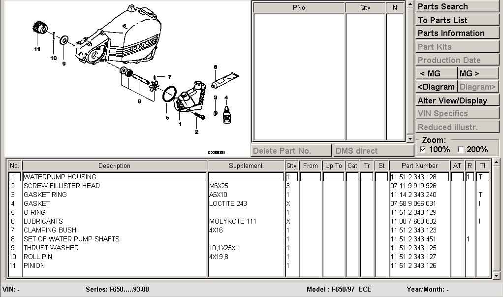
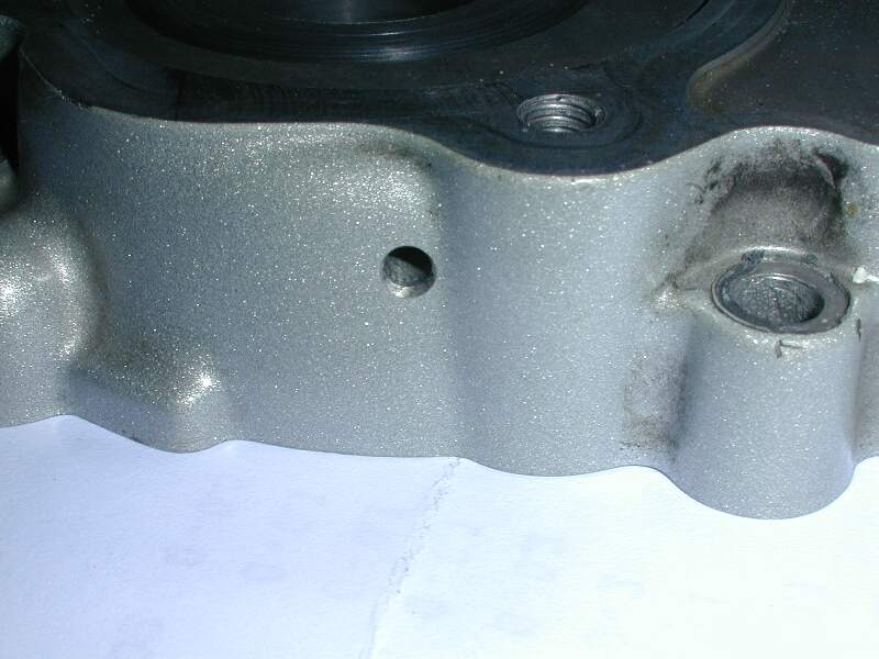
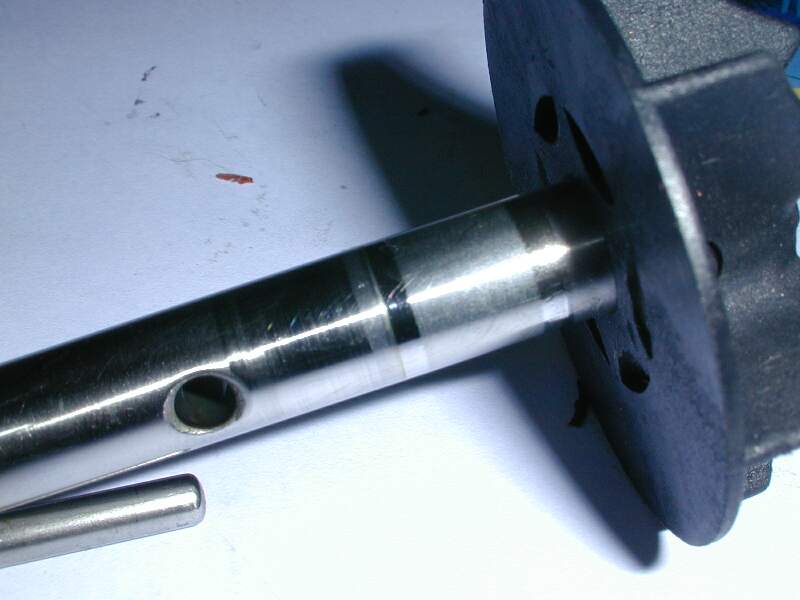
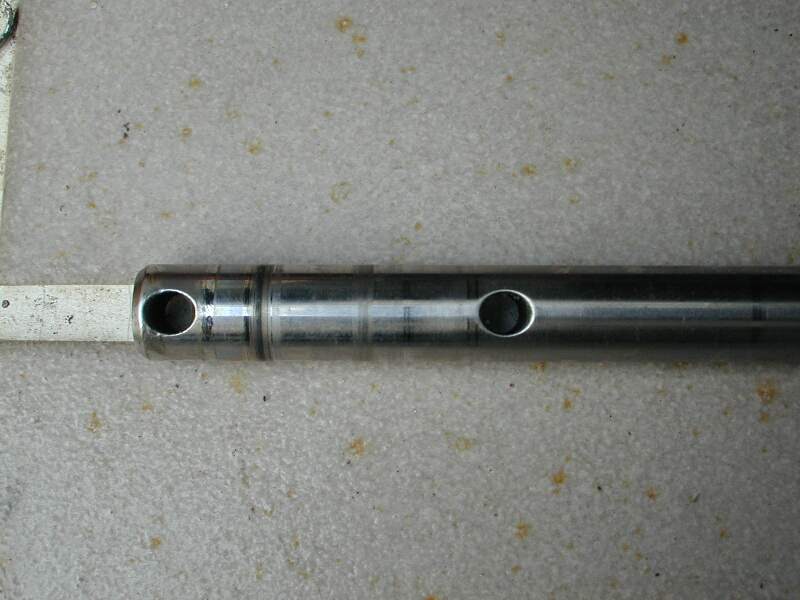
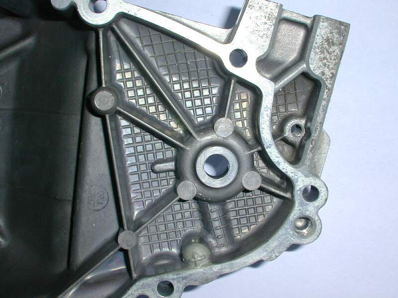
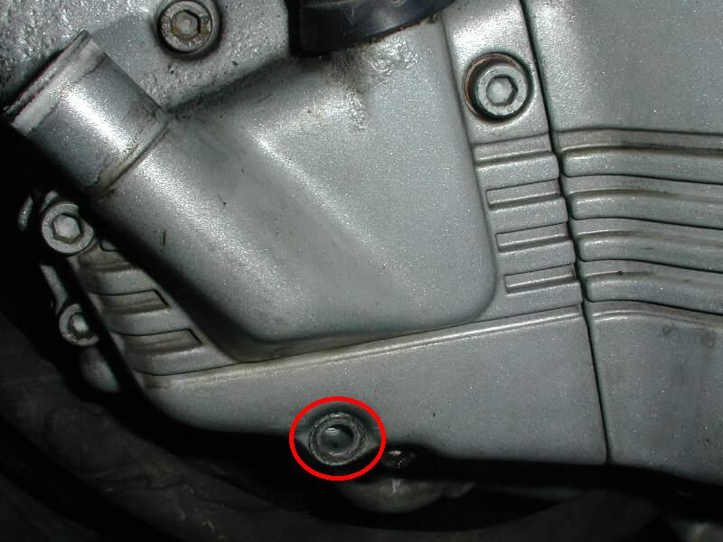
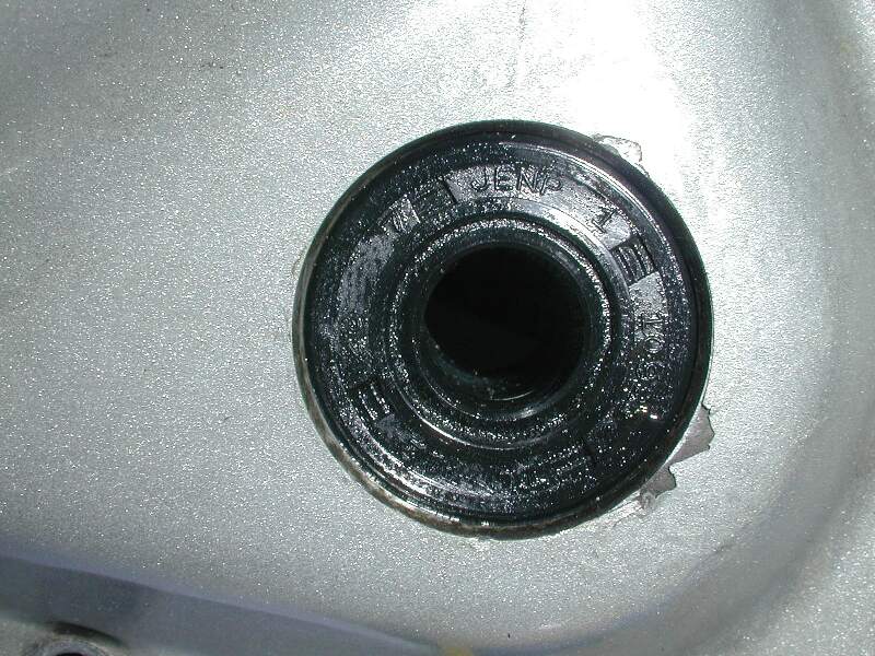
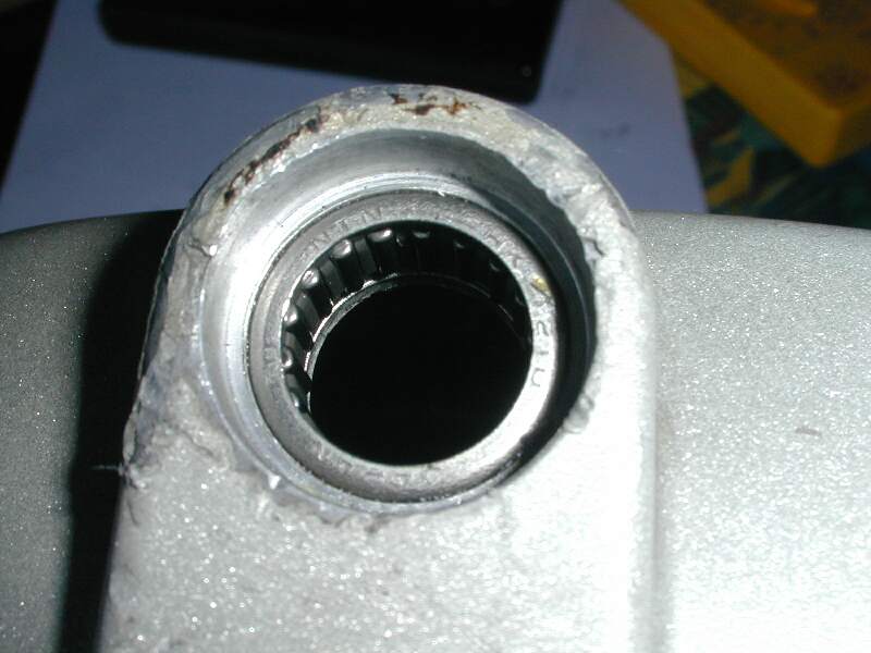
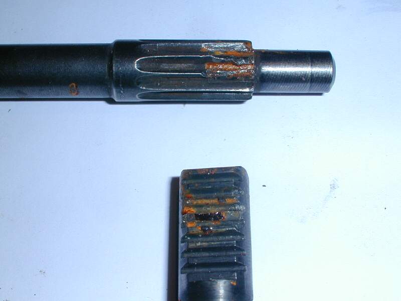
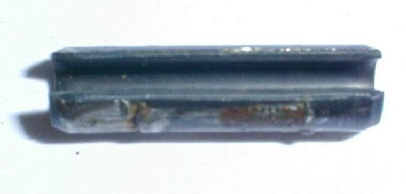
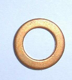
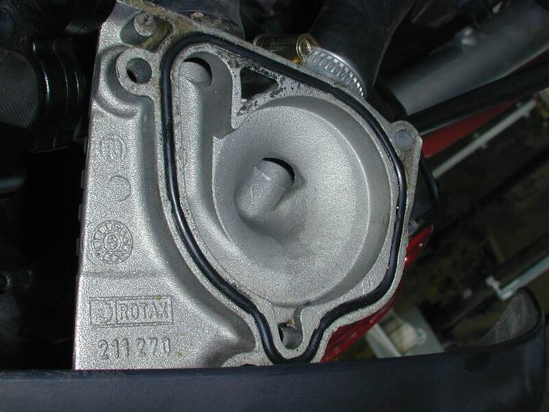
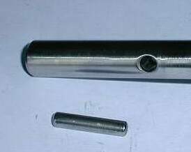
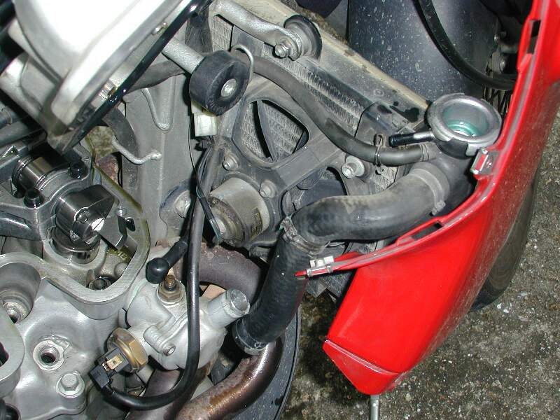
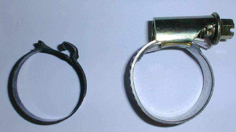
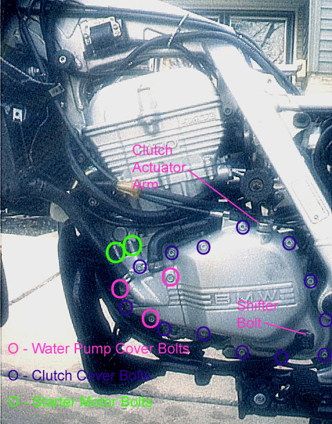
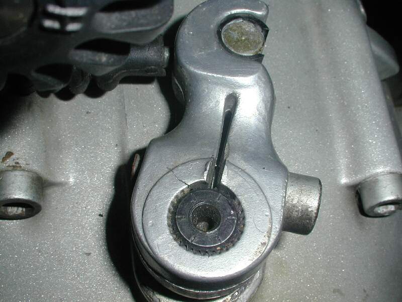
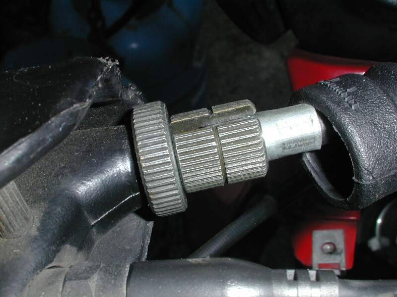
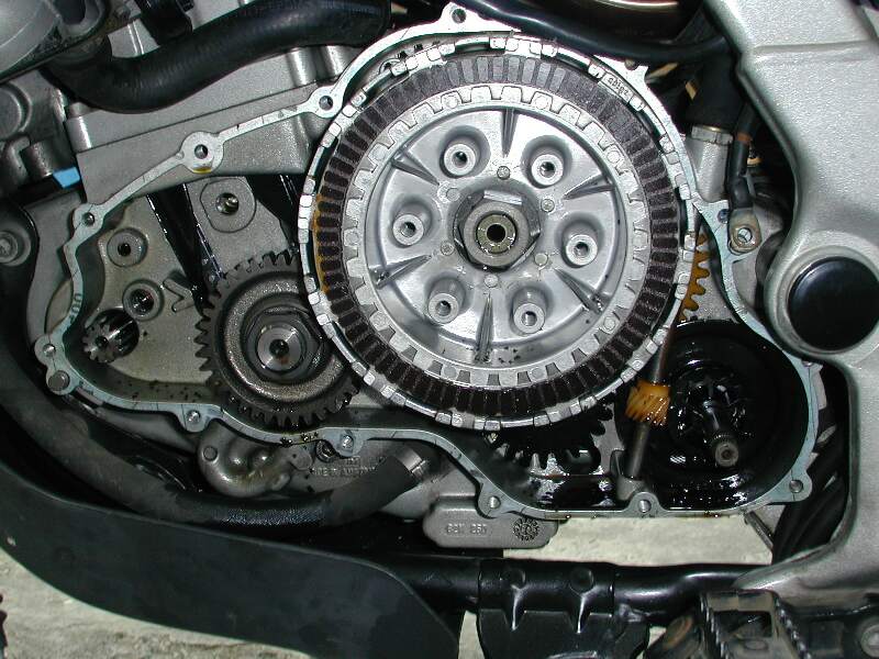
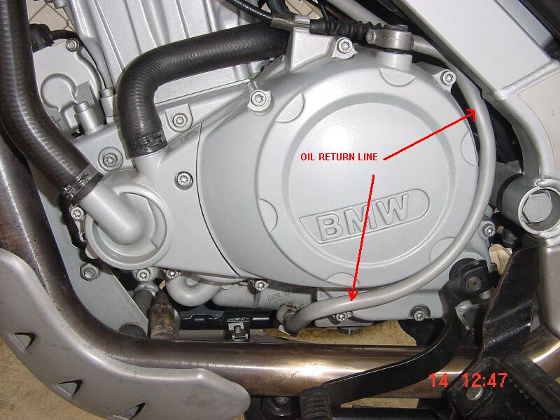
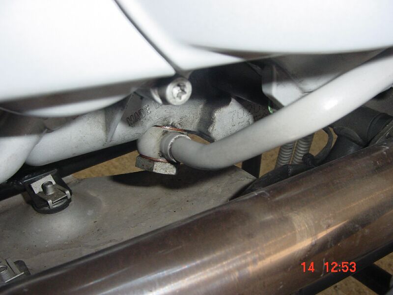
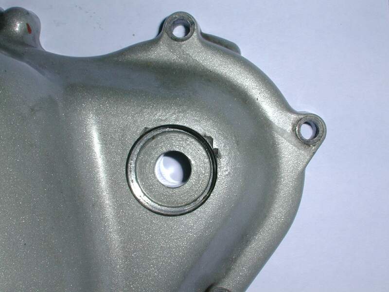
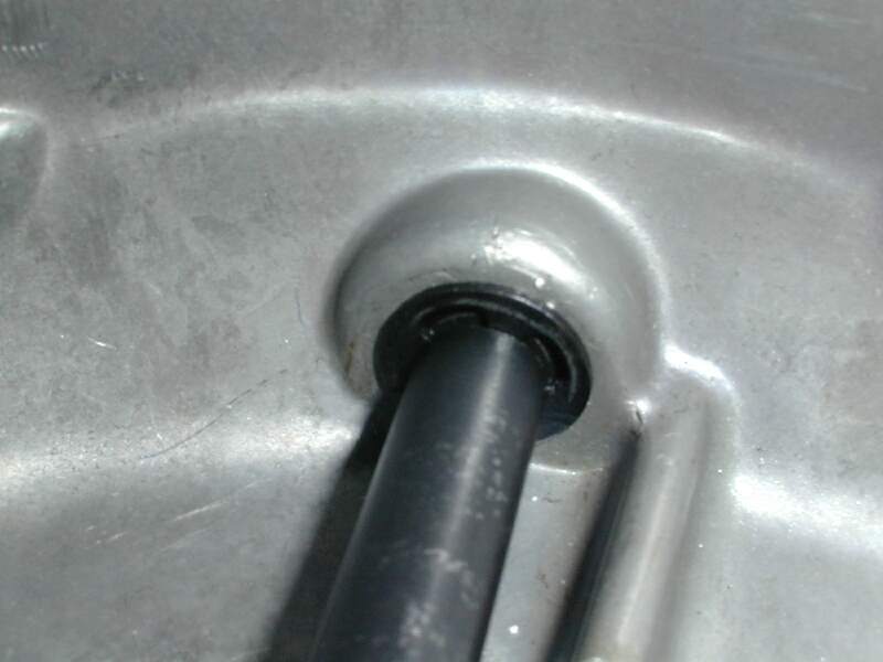
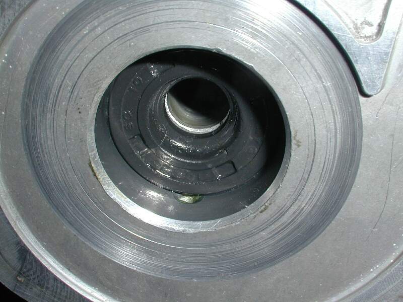
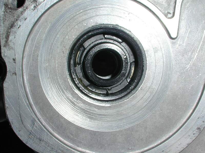
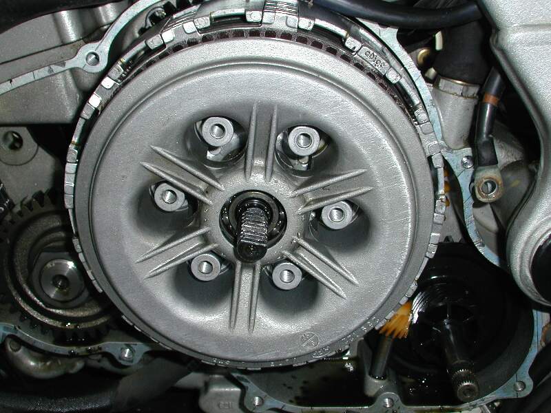
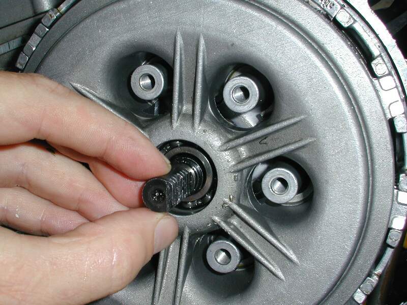