F650 Shock Maintenance
Original FAQs by Kristian #562, BradG #1002, Scott ID #1244
Please read the Disclaimer before
attempting any work in this FAQ.
Last Updated: 21 Feb 2007, by Winter #1935
For FAQs related to forks, shocks, maintenance and aftermarket
options:
Introduction
Tuning and maintaining your rear shock will often make a huge
difference in your comfort while riding. The correct settings and well
serviced suspension may be okay for normal road conditions, but when you
are riding offroad you may need different settings. Not only that, but
well maintained suspension makes riding a little safer - think about what
happens when you apply both brakes in an emergency situation - not only is
pressure placed on your tires, but your suspension needs to work to help
you stop effectively.
Many F650 riders think the rear shock is simply not up to the task, and
state (for instance) the OEM shock needs replacing within 20,000miles
(32,000kms).
ST vs. regular F suspension Differences?
by Harl #380
Unless one is lowered, the suspensions are the same. The only real
difference on the ST is the windshield (or lack thereof) and an 18"
front wheel. The latter may cause you a bit of grief if you want to do any
offroad riding.
GS / Dakar Differences
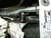
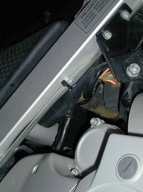
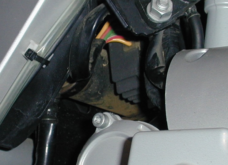
Note that the Dakar has a REMOTE RESERVOIR as well as a preload. On a
Dakar without ABS the reservoir is located here:
Dakar Remote,
Dakar Remote 2.
(Rusty Cylinder above the Oil Filter and to the left of the wires).
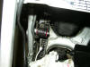
Note that on a Dakar Bike with ABS, the Dakar ABS takes up the
Remote Area and the Remote is moved to the RHS Frame as shown here:
Dakar
with ABS
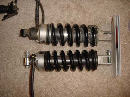
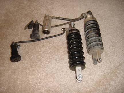
Here is the GS vs. the Dakar Shock Dakar has extra Reservoir,
thanks to Iceman or DHP.
|
|
| OEM Shock Adjustments |
|---|
|
F650 Classic OEM and F650 GS OEM Shock Adjustments are
- Preload: (Large Black Adjustment Knob)
- Rebound Damping. (Small Turn Screw with S<->H stamped on it
at the BOTTOM of the shock, one side only, small turn screw standard
on the fitted shock.
F650 GS Dakar:
- Preload: (Large Black Adjustment Knob)
- Rebound Damping. (Small Turn Screw with S<->H stamped on it
at the BOTTOM of the shock, one side only, small turn screw standard
on the fitted shock.
- Compression Damping (Remote Reservoir). The Ohlins has an adjustor
on the Remote, I'm assuming the GS/Dakar one does too. (Someone please
confirm)
Some Aftermarket Shocks can provide the same as the OEM or give you the
additional adjustment of compression damping via a remote reservoir, like
the GS Dakar, if you're a really full-on rider. if you're not and don't
have money to burn, the Preload and Rebound Damping Adjustments are JUST
FINE. If you do get and you're on the rather heavy side, don't forget to
ask about stiffer springs.
|
Suspension Glossary
Extracted from
Motor
Cycle News... Suspension is a black art shrouded in mystery. Or so the
bloke down the pub would have you believe. Actually for most road riding
setting up your bikes suspension is relatively easy, it is only when you
go searching for those elusive ten tenths of your ability and the bikes
that it becomes more complex.
| Sag
| The amount by which the suspension compresses under the
weight of bike and rider
|
| Preload
| How much the suspension springs are compressed at a
standstill. This determines the sag.
|
| Compression Damping
| Controls the rate at which the suspension
will compress when you hit a bump.
|
| Rebound Damping
| Controls the rate at which the suspension
returns after being compressed.
|
| Rear Compression
| Strikes a compromise between soaking bumps
and squatting under acceleration.
|
| Rear Preload
| Adjusts the initial compression of the rear
spring. This determines sag and height.
|
| Rear Rebound
| Can be set correctly before you ride the bike.
Bounce down on the seat to judge return rate.
|
| Front Compression
| The balance here is between soaking up
bumps and diving under braking.
|
| Front Preload
| Set the sag to be the same at the front and the
back. For an average weight rider, about 25mm.
|
| Front Rebound
| After being compressed, forks should return to
original position without bouncing
|
Other Websites with Explanation of Suspension
Suspension Tuning (Shocks and Forks)
Suspension Tuning for Dummies
Beyond simple seat of the pants tuning there are many approaches to
getting your bike set up just right. The approach suggested here is the
most basic after seat of the pants tuning. The first step requires a
baseline of your suspension. This comes in the form of a pair of
measurements to be taken from your bike. Called sag it provides a means
with which to compare and adjust your bike for the load you normally place
on it (your bum and gear in other words). Rather than repeat the
instructions for this, a link is provided to help you do this. But this
other site is intended for bikes with more adjustments than ours so we
have provided a method that is appropriate for the simpler F suspension.
Go here and skip to Part 2 to
learn how to get your own bike's sag measurements then return to learn
what to do next.
Make sure that when you adjust it, the bike is on the centerstand. This
takes some of the pressure off the spring.
- Measure your existing sag (see above link for details). Suggested
ranges are as follows:
- Front - 20 mm to 30 mm [for the street; off-road you'll want 5-10 more]
- Rear - 25 mm to 35 mm [for the street; off-road you'll want 5-10 more]
- You cannot adjust the front so if it is out of range you need
to change the size of the preload spacer or possibly the springs. See
Tuning the Front Suspension for more.
- If you find your rear measurement is out of the range then you may
want to make an adjustment. The stock rear has only two adjustments:
- Preload - (the large black knob on the right side
of the engine) - affects sag directly
- Rebound damping - (the small set screw at the base
of the shock) - affects how the bike responds to bumps
Some hints that help:
- Initial changes to preload should be made with little or no
rebound damping. At least two (2) full turns anti-clockwise from the full
HARD setting will accomplish this.
- Reduce preload to the minimum. Note how many clicks it requires to
get to the minimum from where it is now.
- If the sag you measured is too small (less than 25 mm) you need to
DECREASE preload but if it is much (more than 35 mm) you need to INCREASE
preload.
- Adjust the preload in steps of five clicks. Measuring between each
change. You can use the number of clicks noted earlier to get you in the
range more quickly.
- Fine tune the preload until your measurements falls in the middle
of the range. You should record how many clicks this requires from
minimum so it can be repeated.
- Now begin increasing the rebound damping in 1/2 turns (clockwise)
until you feel you have the some noticable damping affect. This will be
felt only when pressing or sitting downward on the bike and then letting
it come up freely. As you increase the rebound damping the bike will rise
more slowly after being compressed. You have no control over the compression damping.
- Now conduct your ride tests. A known course that is repeated for
each test is best. It should include some bumps to check damping.
Response to short steep bumps (speed bumps for example) will be different than drops like potholes.
- The goal is to increase the damping only until the rear responds
to bumps in the road evenly. It should not feel springy (too little
damping) or harsh (too much damping) when you have the right amount. It
is important to keep track of your adjustments so you know exactly where
it is set. This allows you to repeat and adjust over time.
- This should get you close. The exact settings are going to vary
with the type of road surface, possibly the temperature and the amount
of load. If you add a passenger or a lot of luggage expect that the sag
will increase and possibly out of range. Increasing the preload may be
required. You can do measurements and testing under these conditions and
then you will have settings for either. Small changes in preload should
not require a change in damping. Large changes in preload will. The
tuning articles provided below give you a much more in depth
understanding of the process.
Feedback on Tuning
'Spring Pre-load' is what sets ride height, and 'Compression
Damping' is what controls the Downward motion of the bike (Upwards motion
of the swingarm) Not the other way round. 'Rebound damping' is what
controls the other motion of the swingarm, which is not adjustable on a
stock shock, hence the popularity of Ohlins shocks.
The primary purpose of spring rates and spring pre-load is to
adjust ride height and suspension GEOMETRY, not suspension function. Of
course stiffer springs will affect suspension function to some degree, but
basically these are adjusted with oil viscosity, compression and rebound
dampening.
After you read some, then go out and experiment. Ride a challenging
section of road. Change _1_ thing. Ride the same section of road. See if
you notice a difference. Write down what you found. Take notes. Then
change _1_ thing. Repeat the experiment. After a while, you'll start to
see what the adjustments do and what you like. Bryan #179
- The suspension is adjustable for various reasons ranging from
weight of the bike, rider, and equipment to varying road (or off-road
conditions). You don't want it too taught because when you go over bumps
your rear suspension won't have enough play to allow for
extension/rebound and you'll wind up tight and bouncing the rear
suspension over the bumps instead of helping absorb them and ride over
them. The weight of your bike loaded for the trip vs. training off-road
will vary greatly so take this into account. I wouldn't be worried about
breaking (note the spelling vs. brake which is confusing in a motorcycle
forum) the shock - but you should focus on finding the setting which for
your weight and equipment results in the best controllable ride (for the
given road conditions). For everybody this is different depending on how
you 'feel' the bike responding to the ride. For example, if I ride your
bike loaded for a trip down a dirt road at 45mph with bumps and humps and
decided to hit them at speed vs. riding the edges and using some braking
before the rough stuff guiding the bike/suspension over the bumps, the
same suspension settings will give very different results. In the end,
it's about how you ride it for a given setting (considering that the
initial setting is okay, I.e.. proper sag and rebound). David #711
I'm NOT an expert. Now, here are my thoughts on tuning the REAR
shock!
The rear shock is part of a system designed to work as a WHOLE. You
can't have the front stiff and rear soft or vice versa and expect the best
handling in most situations. The best you are going to get by asking "How
to tune?" is a rule of thumb approach.
If you want to learn, spend some time reading about tuning and
testing. Keeping good track of the changes you make and making them in a
logical order is key to your success.
In general, for the rear shock, you are better off having the it
set as firm as you can without being a LOT firmer than the front for
riding smooth, well maintained roads. The rougher the roads the more
compliant you want the suspension. Unfortunately the stock bike does not
provide for any quick, on the road, adjustment of the front so extreme
settings of the rear shock are going to be undesirable. When I ride off
road I lower preload a lot and live with the occasional bottoming out. I
never bother with rebound damping but lowering preload would suggest a
corresponding softening of damping to go along with it. Handling off road
demands more travel from the suspension and a softer setup allows the
rear wheel to remain in contact with the ground more. bg#1002
- The rule of thumb I
follow is a motocross axiom. I ride about 80% on dirt so... Get a friend to
help, two is better. Get all your gear on, average cargo, etc. Measure how many
inches from the tip of the tail pipe to the center of the rear axle nut. Get on
the bike, proper sag is one third of the distance you measured. You need help
because one guy measures and turns the knob while the other holds upright as
you'll have both feet on the foot pegs. Now damping control. Screw it all the
way in, ride. Screw it all the way out ride. Take note of the changes in the
bike's feeling. Do 1/4 turns until you are very happy. Now this is NOT OFF
TOPIC: front suspension is very closely related to rear suspension's
performance. Get a set of progressive springs, go to 10wt oil (please consider
that the new springs will displace more oil than regular ones so put a little
less oil in the forks). Do this before tuning the rear end. A very wise man once
said: "Don't just follow advise: experiment!" balam
Tuning the Front Suspension
- There are no adjustments that can be made with the front forks
that do not involve changing the Weight or Quantity of the Fork Oil, the
Springs (Straight Rate, Progressive, Stiffer), adding Pre Load Adjusters
or the altering the Damping Characteristics (Cartridge Emulators). See the
Forks Maintenance FAQ and the
Aftermarket Forks FAQ
for more on modifications for the front forks.
- However, one simple approach to adjusting sag is to change the
length of the 'pre load spacers'. These spacers are found between the fork
caps and the springs. They are made from steel tubing. These can be
shortened (by simply cutting them) to increase sag or replaced with longer
ones to decrease sag (increases pre load on the springs). Similar metal
tubing can be purchased and cut to new longer lengths, you can purchase
large diameter washers and add them to the 'stack' or some have used
schedule 40 PVC pipe. In all cases make sure the new tubing is cut square
and is clean and free of burs.
- If you are curious enough to want to know the 'spring rate' of
your springs you can learn how to calculate it by reading the
Spring Rate FAQ.
So what (settings) are other folks using on their Suspension Setups?
Q. This question is probably
gonna get eyes rolling heaven wards but does anyone know if threes a FAQ( i.e..
what is good for certain conditions on tar and dirt ) on rear suspension
settings for the Dakar? Just got mine 3 months ago and haven't had time to do
the trial and error thing. The manual says if heavy set hard, if light set soft!
Duh! Any advice would be much appreciated.
- The manual is correct :~)). Trevor George, Bristol, UK, BMW F650-GS.
- My missus is very light 50kg and
5'3" But we have set the rear up firm (between middle and hard) and preload to 2
or 3 turns out from hardest she likes a firm ride (no pun intended but what the
hell get some mileage out of it if you can ). Jase, Maniac.
- Harder is gooder. It was easy to
find that just-right setting for my 02 Dakar: I started at full hard, both
rebound and preload, with the intention of working down softer until I found the
sweet spot. But I liked it full-on and left it there. Unless you are very small
or never ride hard/fast, you will probably like it there too.
DakotaDakar
- I'm 5'10" and 145lbs. I just
changed mine to the std setting, 10 clicks from full soft position. I had it at
15 or so clicks from full soft and it was a bit too rough on the crappy roads we
have here. I've only put 700km on the bike so I'm still experimenting.
hk_rider
- I agree with
DakotaDakar, I'm 6' 1" @ 215lbs, and the hardest setting works perfect for me.
On or off road. BeemDubya
- Hard for the road with tyres at
40-41psi & soft for the adventure ride with tyres 20-22psi That's what I have
found after 8 months with the Dakar. KiwiDakar.
- Front end feel? Turn up rear
preload nearer to max , more damping by setting the screw on the shock to harder
, drop the forks through the clamps a few mm , put heavier fork oil in forks.
these will put extra weight on the front end. I've got 20 wt fork oil in not the
7.5 wt recommended. r1speedyrider.
- Change oil to 15 or 20wt. Have new
heavier springs (WP preferred-normally spring rate depends on rider weight but
not in this case, they made only standard spring for Dakar) drop fork about 5mm.
Set rear preload to 100 - 120mm sag. (Full Load) Set rear damping as u ride for
comfort. scx.
- How much do the two
of you weigh? I ride two up all the time with my sons and hardly know they are
there. Total weight for two of us is about 250 or 260 lbs and I don't even set
the shock to the stiffest settings. I will say that they don't like riding on
the F as much as they do on my old Honda--they claim the ride is harsh on the
BMW and not as much room to move and stay comfortable.
Rand #1111
- I had a chance to
ride the new Tiger (wow.....) last month and the owner followed on my F. He
later said he thought it was poorly set up and seemed to fall into curves,
rather than lean. He even thought my tires were flat because of the way it
handled (they weren't). Just wondering if my read shock might be set improperly.
I have it dialled a bit above the "normal" but is it enough? Should it be
stiffer for better handling? I'd like to know what Chain Gangers have set their
rear shock at so I can try a few experiments (next spring when the snow
melts...). How many "clicks" have you set your shock for? Oh yeah - I'm a
"normal" kinda guy, about 160 lbs. I ride mostly pavement, but sometimes dirt
and gravel roads. Paved roads up here aren't always smooth, either, especially
the back roads through the farmland. ichadwick
- How much air is in
your tires? If you don't know... then the odds are they are too low. If you
quote the factory spec... then they are CERTAINLY too low for on-road riding.
Before you mess with your suspension, start with your tires.
Flash 412 (CO)
- I run 34 in front
and 38 in the rear. I'm about 240 with all my gear on and no other load. I can
tell when the pressure is down just a few pounds. I have the RACETECH mods in
the front forks and an Ohlins in the rear. I had a stiffer spring then the stock
put on the Ohlins. The spring I'm currently using is a number 18. The preload is
set just about 1/4 of the way above soft.
- Try 32/35 in your
tires, front/rear. When you sit on the bike, the front and rear suspensions
should drop/sag about the same amount. If the rear drops more, add preload. If
the front drops morel lessen the preload. More preload needs more rebound
damping and vice versa. Is your bike lowered? That makes a big difference.
Harl #380
- I use 33/37 on T66s.
Rear shock is anywhere from 25 clicks (normal) to full (40 clicks?) for fully
loaded or 2-up (this has been slowly creeping up over the years). Haven't messed
with the rebound damping screw lately. The front forks have been modified (for
anti-dive) by fabricating/installing longer fork preload spacers (see FAQs) and
going to 10 wt fork oil. Classic, 180 lb. rider plus Jesses with a lot of tools
and spare parts. Compared to my K75RT, I find this bike very "twitchy" (some
call it "flickable"), which may be what your friend was describing. Tends to go
QUICKLY in the direction of steering input. Marty #436-Chicago-97
F650F
- My rear shock is
dialled in a few notches above normal for a stiffer ride. The person who rode my
F is a tad heavier than I, about the same height (note preening over retaining
my boyish figure...). He is also the motorcycle writer for a large Canadian
newspaper with many years experience under his belt as a rider and not
unfamiliar with the F (although I'm not sure when he last rode one). What I also
want to know is: under normal street/highway conditions is it better to have a
stiffer setting than a softer one? Comfort isn't in doubt: handling is,
particularly cornering. And as a final note: I don't notice anything about the
bike that I considered "wrong" - tires included
- I run my rear at
about 3/4 stiff (whatever number of clicks that is) and with the compression
setting about 3/4 turn down from full. I also have fairly stiff springs and 10wt
oil in the front. My all up weight is about 200 (excludes luggage). The "fall
in" you mentioned in the original post probably has nothing to do with the shock
setting. At least not directly. I suppose a change in geometry from a sagging
rear could affect it but I'm not sure. I think that is why people were focused
on your tires. They are much more likely to affect the bike's handling in that
way. I find the TKC80 tires I run to be very prone to "fall-in" in the turns as
compared to the OEM Bridgestones. If I have the rear shock setup too soft the
bike just seems to wallow (move around) in the turns.
- As I see it; there
are two issues here: spring pre-load and damping (re-bound and compression).
Less spring pre-load means less suspension travel and possible grounding of the
center and side stands in aggressive cornering, especially with the factory low
frame or lowered bikes .Too soft damping makes the bike feel like your riding a
marshmallow in the corners. It is important to match pre-load and damping to
ACTUAL road conditions and LOAD. Steve#1059in MA
- The front wheel
falling into turns is an F650 thing. More so on the classic than on the GS, but
both tend to do it. If you come from a different bike with a similar riding
posture, it's pretty apparent (to me anyway). Try riding a Transalp for a day,
then go back to the F, you'll know what I mean. I think, it's mostly related to
rake and / or trail but I'm anything but an expert on the topic. I can see how
the front tire would affect it as well to a certain degree. Btw, I have my rear
shock preload cranked up all the way (grind stuff too often if I don't) and tire
pressure is 35/38 IIRC. I just found out that I should lose some weight...
(still in denial). its_xls
2001 F650 GSA
- Oh well, a day you
don't learn something is a bad day! BTW=> I run 30/30 tires, and full preload,
and soon full rebound (on road)... Offroad 21/24 (on easy stuff when I'm going
fast) 18/20 (on technical stuff when I'm going slow) Preload exactly half way
and soon no dampening... dumbass
- Just to clarify
before people get the wrong idea. The OEM GS shocks provide COMPRESSION damping
adjustment not rebound. You may have meant that but... FWIW I have tried setting
the rear damping to max. and did not like the results. Way to harsh. The rear
hops over the bumps instead of rolling over them. Give it a try for yourself and
see what you think. Maybe it would work on a good track surface but most of the
roads around here have plenty of lumps and bumps. I never bother to adjust
damping for off road but it would make sense to do so if you lower the pre-load.
The two work together. People ride off road quite differently too. You and I are
blasting about with no luggage and getting air when ever possible. If you were
adventure touring, loaded to the gills, you could not afford to soften the rear
up as much without risk of bottoming out. Brad, N. CA., 2001 F650GS - Inmate
#1002
What setting should I use for the screw on the rear shock?
The '05 stock Dakar rear end is not handling rutted dirt roads well at
all; also, there is a loud metallic clunking sound (the linkage?) at the
back end also. Questions: (i) to improve rutted dirt road rear end
handling, should I adjust the screw on the back shock absorber towards the
'S' marker. At the moment the marker is set as stock, ie. between the 'H'
and 'S' punch mark. (ii) can the screw be turn more than one revolution or
is is strickly one revolution maximum? Fizz
- crank it all the way up and back off in single or half turn
increments until you like the ride. Betty's rearend is cranked all the way
minus a couple of 360's and it is firm but compliant. damalden
#1598
Suspension Linkage
Idler Arm/Swing Arm/Tension Lever Bearings
Many thanks to Haakon #626 for the Numbers
Refer Chain Sprockets FAQ
Swingarm Removal is Easy for details on Swingarm Removal. Refer also
Part Numbers Bearing
Schedule for Parts Numbers.
Idler Arm
There are three sets of bearing
locations on the idler arm, one for the frame connection, one for
the connection to the Shock and one to the Tension Arm.
Two of these have double bearings, and there is one single.
Parts:
- Classic Idler Arm: 2# Needle
Sleeve 22x28x16 - 33 17 2 345 283 - Generic Bearing #
HK2216 (Side by Side at one end of lever)
- Classic Idler Arm: 3# Needle
Bearings 18x24x16 - 33 53 2 345 439 - Generic Bearing #
HK1816(2# Side by Side at other end of lever, 1 in
Middle of Lever)
Notes:
- I only replaced one of the doubles (Both Generic Bearing Number
HK1816), as several needles were broken. Give them all a good shot of
Grease When you remove the swingarm.
- The needle-bearings for the rear swing- arm are 22x28x16 - 4# of
them for the 1993-1999 models. If rebuilding the linkages as well you need
2# more of the 22x28x16 bearings and also 3# - 18x24x16. Haakon #626
- Don't forget there is normally a
sleeve (Bush)
inside each of the bearings, which if it is still in there, must be pushed
out before bearing removal and replaced after bearing inspection /
replacement. These can be pushed out BY HAND. No Heat or force
necessary.
-

 Here are a couple of other photos of the disassembled swingarm.
- Most of these (needle) bearings do not have a cage, they are free
needles and when you Grease them they come out stuck to the new Grease.
The trick is to grease them by rubbing the Grease against the needles and
literally, not lifting a finger. One of the Idler Arm bearings had three
broken needles.
- Lift the seals out with screwdriver, Heat the Metal AROUND the
bearing but not the bearing itself, Nice and Hot (As Flash says, to the
"Leidenfrost" Point, where Spit Sizzles, but good and hot).
Place the Idler Lever (which is fairly robust, if its more delicate place
it on wood), on something solid, with a hole in it.
- Place the Idler Arm with the bearing you want to remove over the
hole (which should be bigger than the one the bearing fits in) and give it
a good couple of smacks using the Drift and Hammer. Wear thick leather or
Cotton Gloves. the Metal is HOT and Stays that way a LONG time.
- In between the frame and the swing arm is a plastic washer and
between the bushing and the swing arm is a foam rubber seal. A leaky
battery vent tube can drip acid onto the washer and seal and basically
eat through them. (Mark #403)
Tension Strut Bearings
Parts:
- Each Strut has one Bearing - Total 2# Needle Bearings 18x24x12 -
33 53 2 345 444 - Generic Bearing # HK1812.
Notes:
- Don't forget there is normally a sleeve (Bush) inside each
of the bearings, which if it is still in there, must be pushed out before
bearing removal and replaced after bearing inspection/replacement. These
can be pushed out BY HAND. No Heat or force necessary.
- Lube them all AFTER you check them for broken needles.
Swing Arm Bearings
Parts:
- Each Side of the Swingarm has two Bearings, total 4# Needle Sleeve
22x28x16 - 33 17 2 345 283 - Generic Bearing # HK 2216.
Notes:
- Don't forget there is normally a sleeve (Bush) inside each
of the bearings, which if it is still in there, must be pushed out before
bearing removal and replaced after bearing inspection/replacement. These
can be pushed out BY HAND. No Heat or force necessary.
- Lube them all AFTER you check them for broken needles.
- To remove the Swingarm youwill also need a PAIR of 22mm Sockets
(Only sockets will do, ring spanners or open-ended spanners will not
work) to remove the swing-arm. A Large Allen key (Not in the Toolkit) is
also a must for tightening/loosening one of the idler arm bolts. Check for
broken needles as above, if all looks OK, then lube well and replace.
Refer the Chain
Sprockets FAQ Swingarm Removal is Easy for details on removal.
- The only thing I'd recommend for taking off the swingarm is bike
on Centre Stand :-), of course remove the rear wheel, and remove the
Tension ARM bolts FIRST, then disengage and remove the bolts holding the
Swingarm, then remove the idler. WATCH out for the plastic Washers between
the swingarm and frame. Tricky to put back.
| Haakon Notes |
|---|
-
 I paid a visit to my dealer and had a long chat with the mechanic.
Unfortunately he had never done any work on the "old" F. (Very
few sold in my area). He had a new swing arm for the GS and the four
needle sleeves that have to be installed in the swing arm prior to
fitting.
I paid a visit to my dealer and had a long chat with the mechanic.
Unfortunately he had never done any work on the "old" F. (Very
few sold in my area). He had a new swing arm for the GS and the four
needle sleeves that have to be installed in the swing arm prior to
fitting.
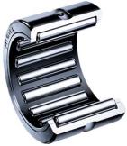
- Those were needle sleeves as the parts database name them.
(See attached diagram to get a grasp of the difference to a needle
bearing, with thick, ground, outer and/ or inner races). When I told him,
the old F used loose needles he almost did not believe me. As I told him
that, all the dimensions were equal between the two he did not know what
to say, except that we were dealing with BMW. The needle sleeve bearing of
course has fewer needles than the loose needle type, but the loose needle
type usually has a much thicker outer ring so altogether the bearing
surface is almost equal.
- Think of the bearing surface as thin lines, one for each needle.
The width of the line does not change much within the range of the needle
diameter. Needles are in the range of 0.5 to 2.0 mm. After that, we
"jump" to rollers. We have a small diameter needle/ roller
inside/ outside a much larger diameter inner or outer race. Thus, the
contact area is a line, slim or "wide".
- I guess the only way to get information on the "old" F
is to, order them (one of each), or post a question to those of the CG
members that have changed them. I will have my samples during next week.
The swing arm one was priced at a bit less than 10 $ US. (In Norway-Nkr
67, 00)
- I "found" this site when searching for good
illustrations: http://www.directindustry.com/
Use the search to find whatever.

|
Maximum Play in Swingarm?
by J@mes#848
Typical Question: Following a tyre change, I noticed that there
is about 1cm of free play in the swingarm when the bike is on the centre
stand. Does anyone know if this is normal? The play is Up - down Side to
side seems ok.
Answer: Should NOT be more than 1-2mm.
Problem: The shock appears to be fine, but the swingarm/shock connection
bearing is shot. I am going for a replacement bearing where the shock meets the
swing arm. For the record that went at 66,000 kms
Rear Suspension/Swingarm Relube
by Langlois
Reason: While doing the 6K on my wife's bike I checked the steering
head bearings and found them a little dry and lubed them. Knowing that
there were many other bearings on the bike I opted to check them and lube
if needed (they all needed it, some were ok, some ideal, they ALL got a
shot of grease)
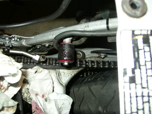
 1. While you are there, pop this chain roller off and lube it.
|
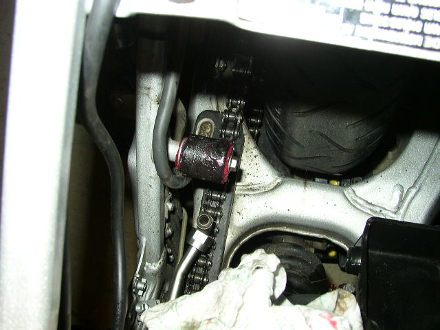
 2. Another shot of that upper chain roller/guide
|
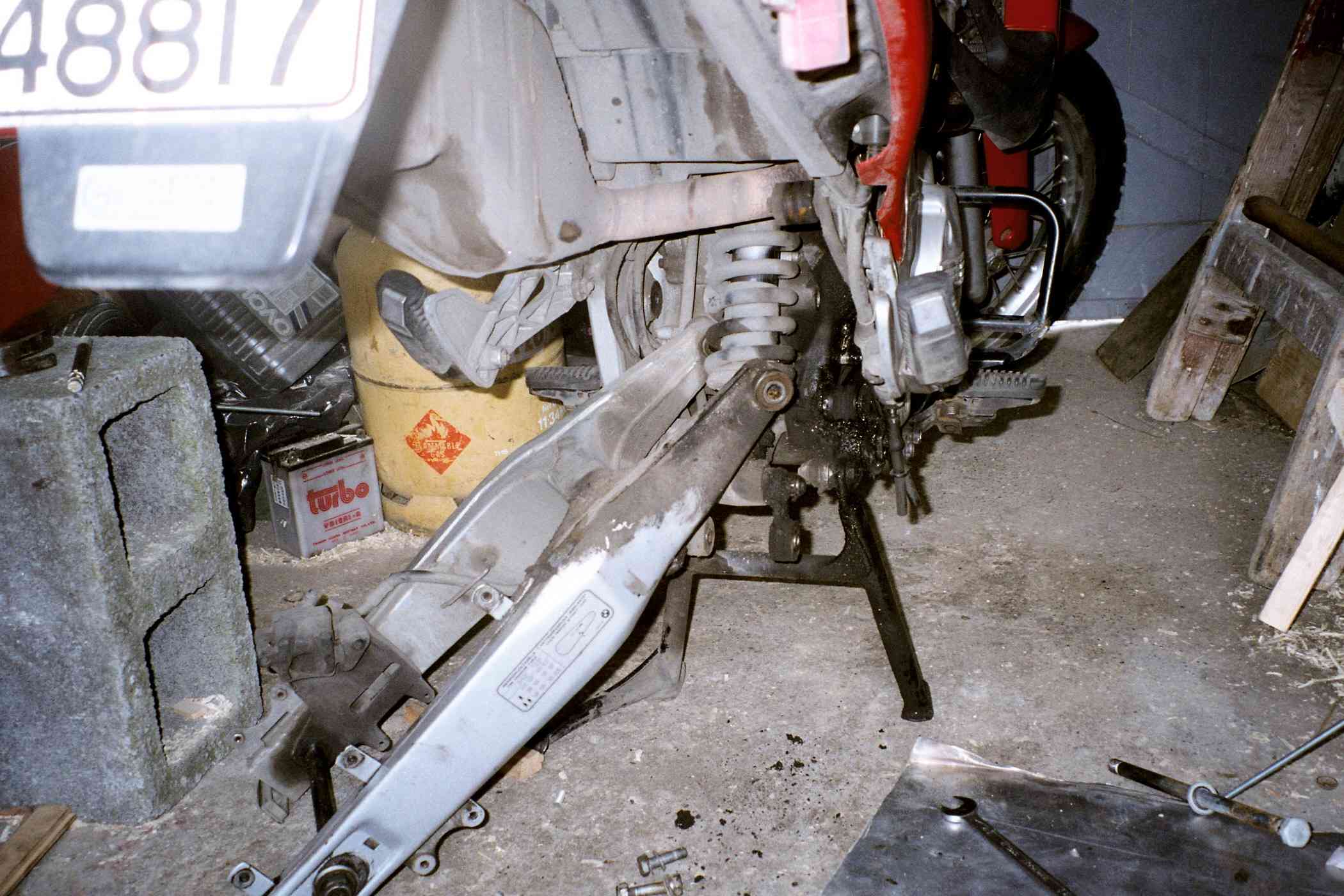
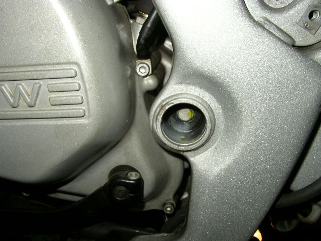
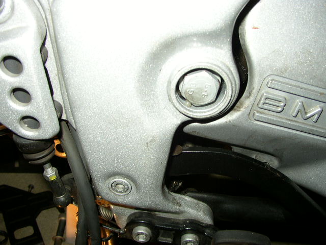
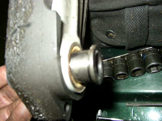
 3. Swingarm, pop off the nut, drive out the swing arm pivot rod.
|
 4. Slide this pivot out.
|
 5. OK swingarm is off, note this seal on the inner and out of each side.
|
 6. This inner bush removes on the inside of the swingarm, note white
seal that wants to be lost.
6. This inner bush removes on the inside of the swingarm, note white
seal that wants to be lost.
|
 7. Lubed (no seal, no inner bush)
|
 8. Lubed, no seal, no bush
|
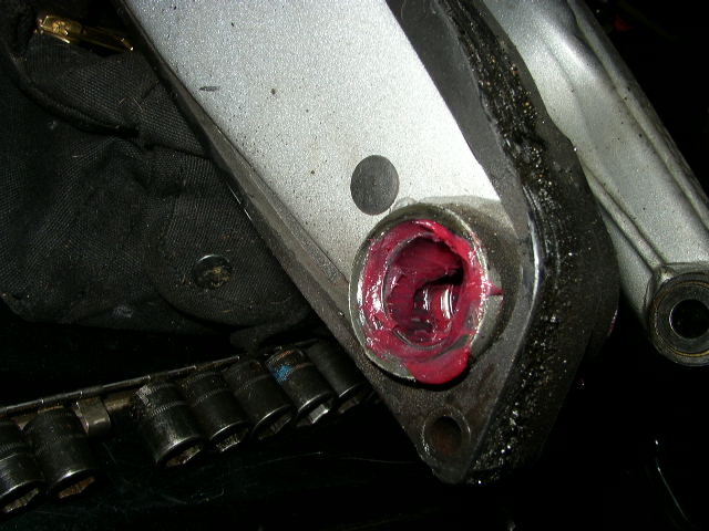
 9. Greasy fingerprints, bush installed with inner seal (a black
washer, plastic, that looses itself)
9. Greasy fingerprints, bush installed with inner seal (a black
washer, plastic, that looses itself)
|
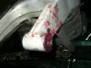
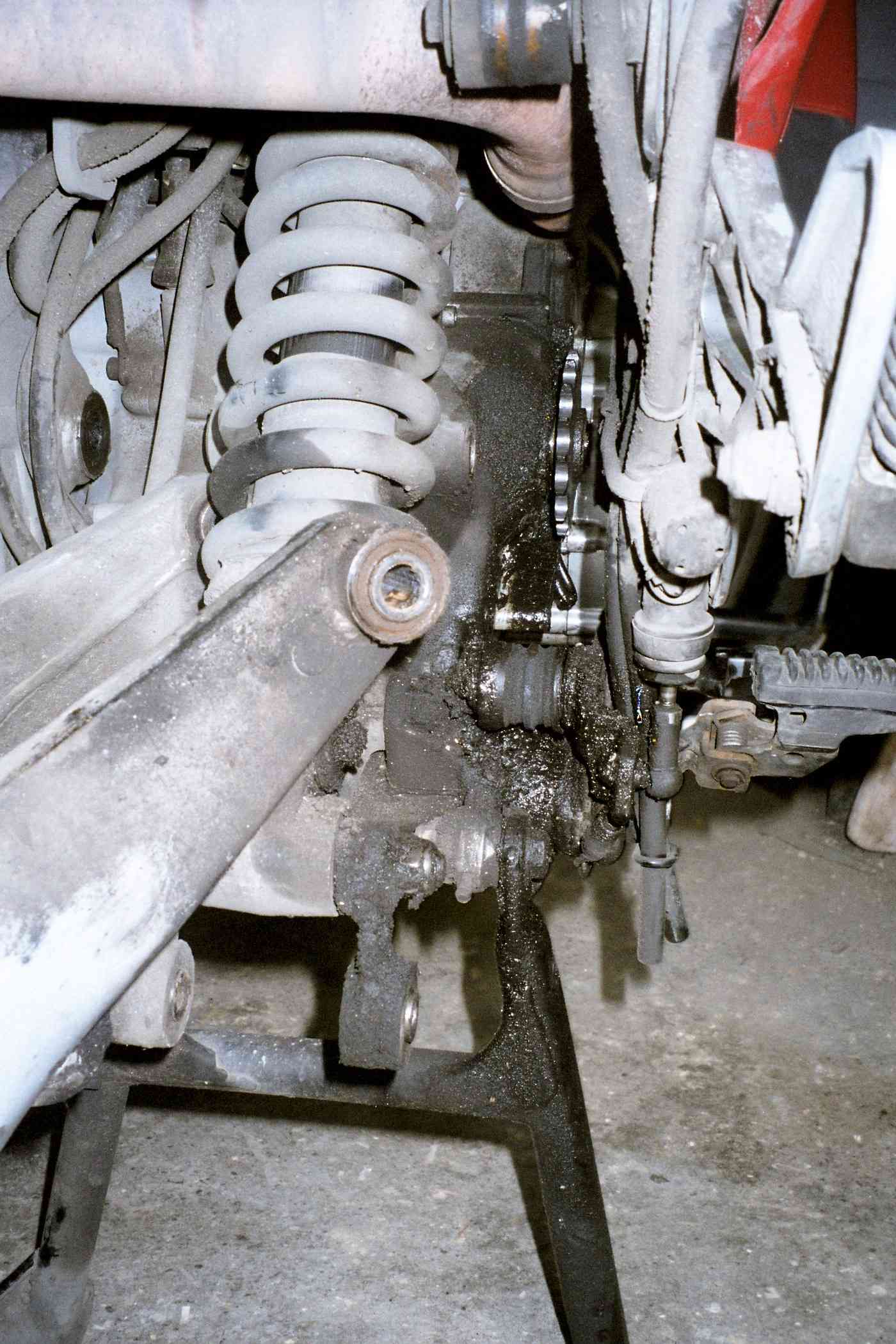
 10. Since you are there....the lower "dogbone" of the rear
suspension needs some attention, take the few moments and DO IT! Still on
the bike (you can do this off the bike) the lower rear needles, not
grease that can be seen, inner bush looks ok.
10. Since you are there....the lower "dogbone" of the rear
suspension needs some attention, take the few moments and DO IT! Still on
the bike (you can do this off the bike) the lower rear needles, not
grease that can be seen, inner bush looks ok.
|
 11. After I get done with grease, messy messy, but hey, it keeps
things from wearing out.
11. After I get done with grease, messy messy, but hey, it keeps
things from wearing out.
|
 12. Removing the dog bone....
|
 13. Lubed, ready to install
|
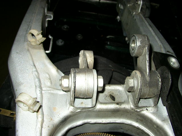
 14. Back to your swingarm: Don't forget these suspension linkages!
They need grease too!
14. Back to your swingarm: Don't forget these suspension linkages!
They need grease too!
|
 15. When reinstalling the swingarm, take the axle, slide it into its
normal "home" take a bungie and hook it up, this acts like
"power steering" and allows you to concentrate on loosing those
little black plastic swingarm bushing washers while doing the install.
15. When reinstalling the swingarm, take the axle, slide it into its
normal "home" take a bungie and hook it up, this acts like
"power steering" and allows you to concentrate on loosing those
little black plastic swingarm bushing washers while doing the install.
|
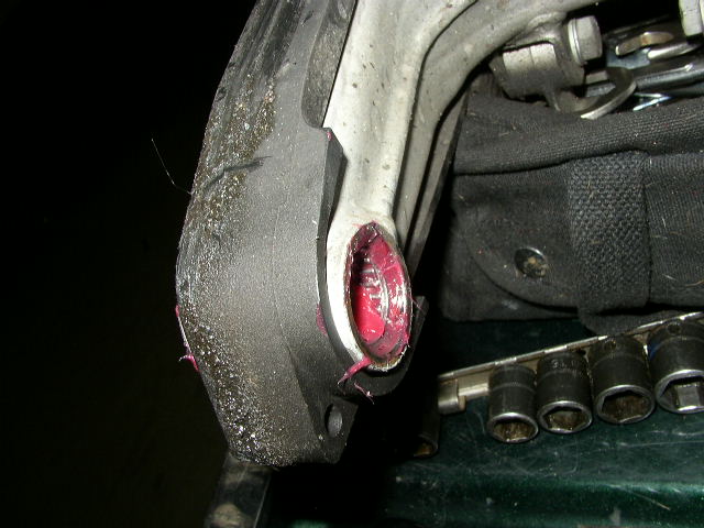
 16. Don't forget the upper shock bush which is a piece of junk plastic
sliding bushing.
16. Don't forget the upper shock bush which is a piece of junk plastic
sliding bushing.
|
 17. Since you are there...take the adjusters out of the swingarm,
clean them up, antiseize the threads.
17. Since you are there...take the adjusters out of the swingarm,
clean them up, antiseize the threads.
|
Suspension Linkage Feedback
-
Lubricating suspension linkages. As I have the swinging arm out to fit an
endless chain it seemed like a good opportunity to inspect the myriad needle
rollers lurking in the linkages. On my 18000 miler, all seem good and tight
and free from corrosion. (especially given their position exposed to all
sorts of nasty fling from the back tyre.) The bearings and swinging arm
pivot bolt didn't look over oily so I started packing generously with moly
grease before wondering if this is the right stuff. Any recommendations? I
was pleasantly surprised at how easily the arm came out, and the peace of
mind of having a factory riveted chain is worth the small amount of extra
fuss. Likewise the linkages are no problem to take apart, and not having
greasing points will thank you for lubing them. If nothing else, ordinary
grease will prevent water from getting in as corrosion will kill the
bearings quicker than loading. The arm is still to go back in, but the
easiest way looks to be to connect the linkages to the shock first so that
the weight of the arm is taken whilst you line up the pivot with its two
large thrust washers. Tony
-
I use
BMW #10. I like that stuff. I find the swing arm a pain to replace. the
plastic washers on the outside want to get lost. I stick them on with some
grease, then slide the s.a in place. usually takes a couple tries dropping
one of the washers. then I get smart and MOVE all the hoses in the way that
knock the washers off...then it goes on easier. I've always done it without
the linkage in place. I think it's probably easier to get the s.a. in place
without the linkage, than get the linkage in place without the pivot... at
about 18K, I replaced all the seals on the linkage and the foam seals on the
pivot. everything was actually still in good shape, but I got a wild
hair.... I'd also had some battery acid drip down the side and eat away the
left side foam seal on the swing arm pivot, so i guess not EVERYTHING was in
good shape. but all the metal/rubber seals were good. personally, I prefer
not to remove the swing arm if I don't have to, although it does come off
once in a while for various reasons. on the chain, I use a rivet tool. Mark
#403.
-
When
I re-lubed my suspension bearings I used BMW #10 grease. If I did not know
about and have a tube of that grease, I too would have used moly wheel
bearing grease. I guess the only concern would be what did BMW use at the
factory and would your new grease adversely react to their grease. I don't
have an answer to that question, all I know is that the #10 grease seems to
be working. Richard #230
Suspension and Swingarm Linkage Bearing Replacement
Many thanks to Kristian#562 (ex-FAQ Master) for this write-up. [Ed note: Use the images for lubing the bearings for a general guide on what things look like]
Sequence
- After removing the rear wheel, undo the link rod connections to the swing arm first. This is the bit under least tension and will get you access to the rest of it. Then remove the swing arm main bolt (2 x 21 Sockets).
- Pull out the swing arm. You WILL need to remove the plastic chain guard (3 screws) to get it away from the chain and thus away from the bike.
- Then undo the bolt holding the shock to the idler arm. Then undo the final bolt (a 14mm and a 16mm) holding the Idler Arm to the frame.
- You should then have 1 Swing Arm, 1 Idler Arm and Two Link Rods, plus a bunch of bolts/nuts.
- Undo the black plastic Swingarm chain runner, the one that runs around the RHS of the swing arm and protects it from the chain. It is fastened by TWO (probably VERY RUSTY) screws, which you will likely shear off. Crap Design. Try a little WD40 overnight... you may have to resort to heat ... Take GREAT care with the Plastic but, It is not RUBBER it is BRITTLE plastic. Do not BEND it. It WILL break.
- Gently prise off all seals. The Swing are arm and one idler seals are spooge. See below.
- Take out and replace all bearings as per instructions below.
- Re-attach chain runner (brittle plastic) and using some anti-seize on screws is a GOOD IDEA. Then replace chain guard.
- Attach idler arm to bike frame (1 bolt). Then attach shock to idler arm (1 bolt, no nut). Then install the swing arm and long bolt in place (2 x 21 sockets for the GS, 22mm for Classic IIRC). Then attach the link rods and then mount the wheel/tyre. See rear wheel replacement FAQ for that. Done.
Parts
You do NOT NEED to replace ALL the Bearings. I just didn't want to do 1/2 this job now and 1/2 later. Your choice. Water does it get in, if your bike lives outside 365 days a year, like mine.
- The Pull-Rod/reaction Link is listed here (correctly) as 1# 18x24x12. Don't do what I did and forget that's one Brg for EACH Link, and only buy one... i.e. ONE PER LINK ....=> BUY a total of TWO of THESE => Pull rod / Reaction link BRG 18x24x12 HK 1812 F650 GS/ GSD.
- For the GS/Dakar, there are a Total of 6# 22x18x16 Brgs, 3# 18x24x16 Brgs, and 2# 18x24x12 Brgs. Total 11# Brgs. Suggest first timers buy an extra 22x18x16 in case they mash one because they (a) Got it off-centre with the Vice (b) Used too little heat (IF USED) (b) Used a socket to drive it in that wasn't exactly the right size (c) Got it wonky at the outset then continued to drive it rather than try to straighten it or remove it and start again.
- Don't forget to buy ALL new seals too ... I have all the numbers at home, will send them later. Basically same (internal/external dia) as above except last number (always thickness) is 4mm (large bearings) and 3mm for the smaller bearings. If no 3mm then 4mm is OK, just make sure the Brg is deep enough in the sleeve/hols to allow a 4mm to fit. Totals: 4# for Swing Arm (All Large), 6# for the Idler Arm (Two Large/Four Small), 2# for EACH Reaction Link (4# Total). Overall Total 14#. Buy an extra of each....
- Some Grease!
- The main swing-arm to engine frame uses some cheapo sponge-type seals. I couldn't get those except maybe from BMW, so I just used the same (new) single-lip seals as for all the other bearings of that size. Fits well and will probably hold water out better than those spoogy ones. Cost-cutting measures from BMW or real purpose? There is also one other (smaller) sponge-seal which I replaced with proper seals. The number of seals in (3) above assumes you will NOT use the BMW oddity.
Driving Out Old Bearings
- The Main Swing Arm and TWO of the THREE Idler Arm Holes have TWO Bearings per hole. For sleeves with TWO Bearings per hole, when driving them out, note that (there appears to be) a slight taper toward the middle. If not using a vice, DRIVE the bearings out from inside OUT. Do not try to drive the bearings through to the opposite side, it may jam. Drive out the first one (of a pair) using as large (largest diameter) a punch as possible that will properly fit the lip. A large dia. will do LESS damage than a small dia. one. Do NOT use a Screwdriver, you will score the aluminium of the Idler Arm. The Main Swing Arm Bearings are seated in a STEEL pipe, so this is not so much a problem for those. Once the FIRST brg is out (using the drift) you can then use a perfectly sized (or very slighter smaller) SOCKET to drive out the second one, AGAIN inside to out. The single bearings are in straight-sides holes. No taper. If you happen to score the aluminium a bit don't cry it's not a disaster. The new bearing won't fall out. Just make sure there are no burrs sticking up. If burred, LIGHTLY smoothen with a piece of VERY fine wet and dry sandpaper.
- EITHER...
METHOD A: Recommended - Use a Good Strong Wide Opening Vice. A small vice may simply not have enough leverage. Put a Socket the CORRECT hole size on the push-in side and a LARGER than Bearing Size Socket (or piece of pipe, steel with hole in it) on the push-out side. Crank with VICE. If it appears it isn't working, you may need to apply some heat. This method will do LESS damage to your bearing housings than HEAT, but you MUST have the correct socket. If bearings REALLY stuck or rusted in, you MAY still need heat.
OR METHOD B: Use Heat. Not pathetic amounts. Use LOTS of heat, especially on the steel tubes of the swing arm. NOTE: The paint will burn off, so you may need to repaint. For this method, there is NO substitute for LOTS of heat. Use a BFH and put the item you want to work on, onto a piece of wood. The idler arm is the wonkiest shape, so it always tries to tip over when you hit the socket. Cut grooves and slots in a piece of timber so that it sits FLAT. Drill HOLES in the timber so you can DRIVE the old Brgs through and out. Driving out the single (and small) Link-Rod bearings is the easiest thing. If you haven't done it before do those first, over a piece of timber with a hole in it, just larger than the bearing OD. If heat is used, be patient. Have all your tools around you, including heat (if used). Have a pair of heavy leather or other heat resistant gloves (if heat used).
- Be patient.
- Be a little more patient.
- For the Swing Arm. A two-pronged hammer-type bearing puller didn't work for me. Maybe not enough heat, or too much resistance holding it. Slotting the sleeve (with the Brgs in that you to drive out) over a workbench, I drove the INSIDE Brgs out using a drift first as they were easy to access from the outside of the swing-arm. Remember (IF USED) HEAT and a DRIFT is OK here as it is a steel sleeve. I then used a socket (of exactly the right size!) and popped it in the hole from the inside. I threaded a socket extension (3/8" or 1/2" drive) through the OPPOSITE-side bearing sleeve and clicked it into my socket and drove that. Repeat for other side.
- Swing Arm again and only if heat is used, strongly suggest you do NOT try to just stand the swingarm on its side and whack the bearings out of the unsupported (upper) arm. Not that the thing will bend (unlikely, deep box section) BUT it will bounce a lot, so you lose a lot of energy in rebound, rather than going into driving the bearing out. This is where a solid workbench comes in handy: (a) For the INSIDE BEARINGS: You can rest one sleeve on the workbench (or over an anvil, over a piece of wood with a hole in it) and the other sleeve will be BELOW the workbench. (b) For the OUTSIDE BEARINGS: You can rest one sleeve on the workbench (or over an anvil, over a piece of wood with a hole in it) and the other sleeve will be ABOVE the workbench. In both cases whack the bearings out of the sleeve that is sitting DIRECTLY on the workbench (over a piece of timber with a hole in it). You might need to suspend or support the rear of the swingarm (axle-end) or get someone to hold it for you. Simply using A vice may be easier, (i.e. NO heat), but ensure your sockets are correctly-sized.
| sunio's hint on bearing removal |
|---|
I first tried to hammer the bearings out (using torch to heat things up) but that's not the way to go! A much easier way is to simply press them out. I used a large wise and sockets of the same (well, slightly smaller) diameters as the bearings. With a help of piece of wood to protect aluminum parts I simply pressed the socket in and it in turn, slowly pushed the bearings out without damaging them. On the opposite end where you're pushing the bearing you can put a larger socket so that the bearing driven out falls into it. Same for installation. Very precise and will not damage you bearings or suspension components.
- You only need a vise. I have mine sitting loose on the garage floor :). That's enough. It only has to be large enought to accomodate the widh of whatever houses the bearing + the sockets lenght + a bit more.
- I did press double bearings the same way and no there is nothing between them so you can do it from both either side.
- I am not sure what sleeves are (english is my second language, sorry) but if you're talking about the steel tubes that are between bolts and the actual bearing then those came out easily by sliding them out by hand.
- Actually using this method you can take the bearings out, clean them properly, relube with a grease and reinstall them. You won't damage them at all. I only ended up replacing 6 of them. I cleaned and relubed the reminder of them
|
Replacing Bearings
- Put your Bearings in the freezer or have your spray-can of liquid nitrogen at the ready....care esp. with the latter, if you value your finger tips.
- EITHER...
METHOD A: USE A VICE. This time, use the vice and a piece if timber to "push" each bearing in from it's own side. Once flush, use a correctly sized socket to "push" it in the extra 3.5 to 4mm you need to provide the recess for installation of the seal.
OR METHOD B: Use LOTS of heat. ESPECIALLY for the Steel Swing arm sleeves. The aluminium idler arm and link rod sleeves didn't appear to need "quite" as much heat. One bearing in a two-bearing pair even dropped too deep into the hole with no driving. It cooled and I had a hard time getting the bearing back up into place again, so watch for this too.
- For the Idler Arm, have your piece of timber with all the right grooves in it so the piece lies FLAT and does not wobble. For the swing arm follow the same advice wrt the workbench or anvil as above. Method B Only.
- So put you hotty gloves one, heat the sleeve, race inside, get the bearing out of the freezer and slot it in the hole. Make sure it is true. You won't have time to make sure of this for longer than about 0.05 seconds. Then place a bit of TIMBER (WOOD), the harder the better and use a nice solid block, over it and whack it in the middle of the timber. Whack it hard and whack it quickly try and make sure it is going down evenly. Do NOT use a socket at this time, not until its top is flush with the end of the sleeve. These are NOT like solid thick steel wheel bearings, they have a THIN SHELL cage ... hit it incorrectly and YES it can buckle. You did but a spare didn't you.... you don't have much time, at least for the steel swing arm. Once the bearing is flush with the sleeve-end, THEN get your (correct size) socket and whack it down the last 4mm. Don't stop short, or the seal will just pop out. Do not go TOO deep either. All this must be done quickly, but don't RUSH it. Method B Only
- Depending how hot you got the idler arm, you might be able to get 2, or even 4 bearings in with one heating session, try it, but don't push your luck Have your helper race out with the frozen bearing. They do NOT stay frozen for long, they are so thin, they can't hold the cold. if in doubt freeze it again and heat the sleeve again too. Method B Only
- Do not put in the SEALS until the thing has cooled. Apart from finger burns, it might melt the rubber.... So once cooled (maybe you can help this along under warm then ever cooler water, but don't "quench it" in cold water from blazing hot, this "may" make the sleeves brittle.
- Once cooled, insert seals (preferably on a dry non-greasy surface) .... you DID make the brgs deep enough right? If not do NOT try to drive the extra 1mm cold, you will just munch the brg. Either use the vice/socket combo, or apply heat again (and allow to cool). Slather the bearings with grease, roll around. Insert steel Sleeves. Replace on bike in order as A to I above.
Tools
- Correctly-sized sockets that JUST fit the bearing hole, pref, with a wide flat lip.
- Heat Source (IF HEAT used) e.g. Blow Torch.
- BFH (IF HEAT used) (BIG *** HAMMER).
- 21mm, 14mm, 16mm Sockets and Ring Spanners (There may be other sizes required?) for Idler/Swing Arm removal and replecment.
- 19mm and 24mm for Rear Wheel ???
- Various Torx Spanners for Removal of Chain Guard and Plastic Bits. 8mm ring spanner for mud flap removal.
- Phillips Screwdrievr for removal of chain guard rail.
Shock Disassembly
How do I replace the Shock
Generally, follow the Ohlins
Installation FAQ. There's some more specific guidance and even some
photos in these FAQs, to be followed in this order:
- Rear Wheel Removal/Replacement
FAQ
-
Swingarm Removal FAQ. Do NOT remove the Swingarm though, just follow
steps 1 and 2.
- Ohlins Installation FAQ
-
Swingarm Removal FAQ Do NOT remove the Swingarm though, just follow
steps 14 and 1
- Rear Wheel Removal/Replacement FAQ
Consider perhaps also taking the Tank off so you can see what you're doing up
at the top.
GS Shock Removal
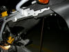
In order to access the top mounting bolt of the GS shock, it appears the
fuel tank must be removed, and that in turn requires removal of the rear
subframe, etc. What a difficult and complicated job simply to change a shock, or
am I missing something? Any advice/info on changing the shock on a GS will be
greatly appreciated.
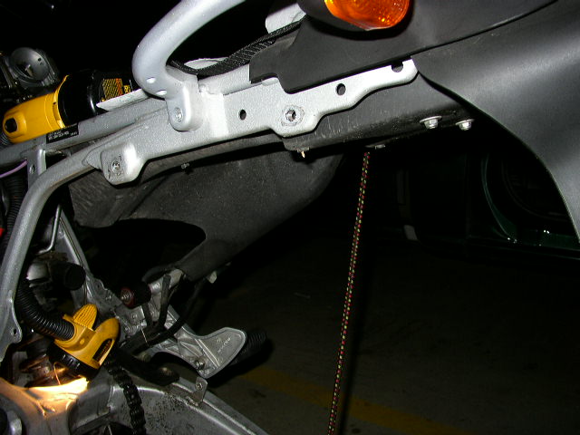
- According to the manual the rear frame has to be raised slightly
by removing the bottom bolts and loosening the top ones. This is done with
the tank installed. A picture shows a strap from the rear frame connected
to the crossbar on the handlebars to hold the rear frame up a bit as you
remove the shock. Good luck. Homeless (CO).
- Rear subframe removal indeed makes shock change much easier and
the subframe removal is very simple. Take the subframe, muffler and fuel
tank off as a unit. It will lift right off. It may be helpful to have an
extra set of eyes and hands so a helper will make the job go easier.
Stuportech.
- I did finish the rear shock installation on my GS however, I'm not
sure I did the job in the best way. Supposedly, it is possible to simply
remove the bottom subframe mounting bolts and raise the entire rear of the
bike (using the top mounting bolts like a hinge) enough to expose the top
shock mounting bolt. That avoids having to disconnect all the electrical
connections, hoses, and exhaust pipe which "bridge" between the
front of the bike and the rear unit.
However, I absolutely could not find a way to do that because the
rigidity of the exhaust system prevents it. Thus, it is necessary to
detach the muffler and cat from the rear of the bike, and I couldn't
figure out how to do that. There are excellent instructions, complete with
color pictures, on the Cycoactive/Touratech USA website
www.touratech-usa.com/f650rr_instl/english/index/html
It has instructions for removing the rear subframe (these are part of the
Touratech Rallye Bike kit instructions), including directions for
removing the muffler and cat, but it didn't work for me. Possibly it would
work if the header pipe was unbolted from the motor, but I doubt it and
did not try that. So, I wound up removing the entire rear assembly in one
piece by separating the exhaust where the two sections of pipe join.
It actually simply involved separating everything I came across which
joined the rear section of the bike to the front, one by one - five
electrical connections, two or three hoses, the exhaust pipe clamp, and
the four subframe mounting bolts, then simply pulling off the whole rear
unit (best done by two people). Mike #926.
Missing Strut Nut?
Decided to clean the chain and while working in that area, it appears
that the nut on the bottom of the rear strut/shock is missing. Good reason
to clean your bike btw. You can check to make sure everything is still
there. In this case, I've never actually noted it was even there and I
guess there's a chance that there wasn't one there or one isn't supposed
to be there. Can't imagine why not though. I did check the CD-ROM and
can't really find a good reference to it either. This is an '01 Dakar but
I suppose they would all be the same. Gerry #951.
- It's not missing. There IS No nut installed. While out &
about, I stopped by Victory and the F650's don't appear to have one
installed. Gerry #951
Shock Disassembly Procedure
(by Ralf Wolf)
How to disassemble the rear shock without special tools or taking
unreasonable risks:
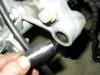
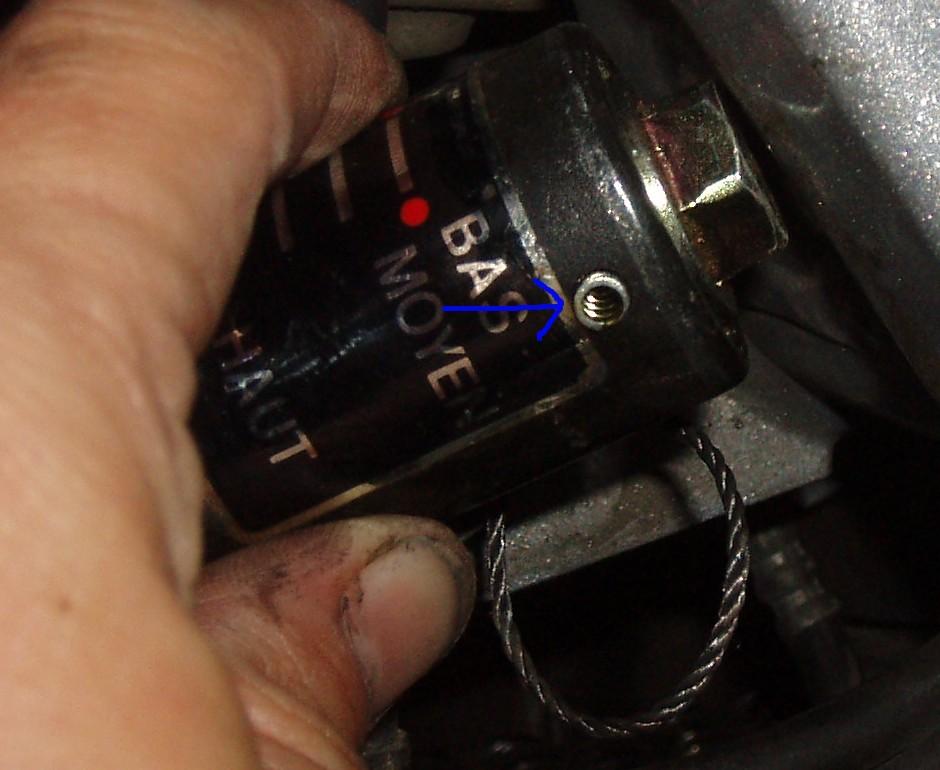
- Remove the shock and pre-load adjuster as a unit.
| Note: The pre-load adjuster is easier to thread
through the frame with the knob removed. Just be sure to catch the
spring loaded B.B. that is used to make the 'clicks' when you adjust it.
Photo 1 shows the spring loaded hole the B.B. lives in, after the cap was
removed and my first B.B. went for a ride....
|
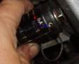
Figure: Preload Detent BB holder Hold
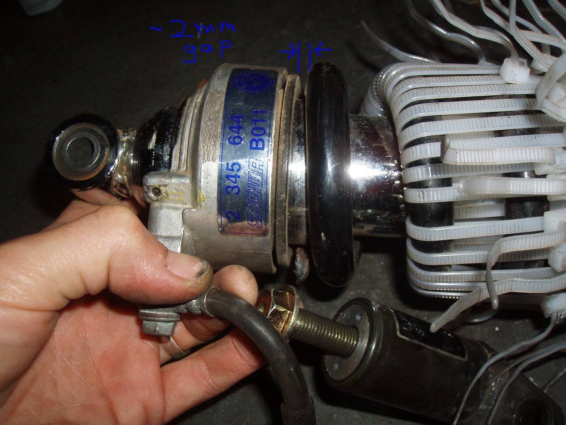
Crank the pre-load up to maximum to pre-load the spring. Once
pre-loaded, install about 40 zip-ties to the spring as shown. Be sure to
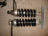
cinch them up nice and snug, with an even tension on all the ties. (see
photo 2)
Yes, this is ugly, and a waste of $5 worth of high quality zip-ties,
but it really only took about 10-15 minutes to lace up. For the garage
mechanic, it's quicker/cheaper than a trip to the dealer. Maybe I
could've used 1/2 as many zip ties, but I didn't want to take any chances
with the spring popping loose!
Don't use cheapo zip ties! Get the good ones, with ratchets on both
sides. As a test, make a big loop out of one of them and try to break it
with your bare hands. If you can break it, buy bigger/better ones before
proceeding!
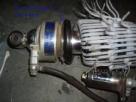
Figure: Zip Ties Installed with Pre-Loader Maxed
- Crank the pre-load to minimum and make sure the spring is loose
by a few mm, as in photo 3. If you have any doubts about the strength of
your zip ties, give them a poke now to see if any are about to pop off.
|
Note: Only proceed if you are confident that your zip ties, or
whatever you used to hold the spring compressed, are going to
hold. If the ties pop off after you do the next step, you can't
reassemble the shock!
|

Figure: Preload Removed to Get A Small Gap
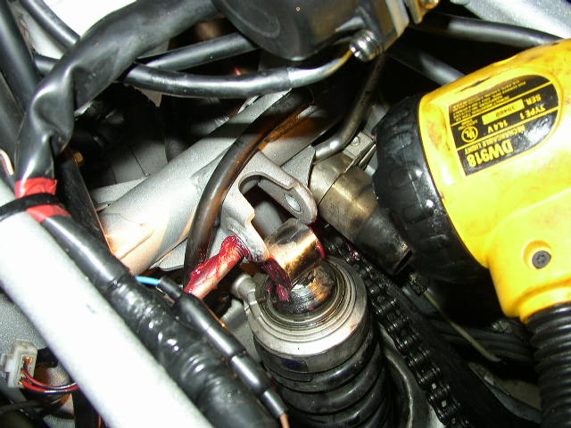
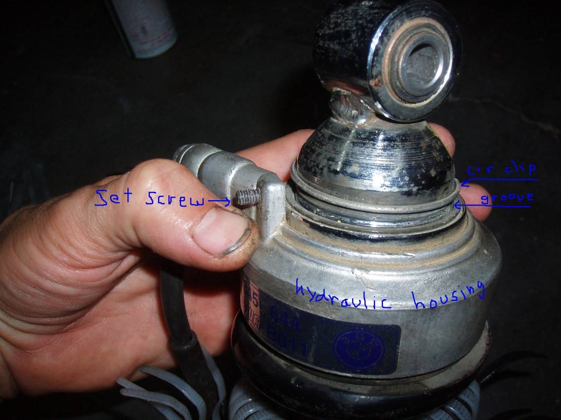
Loosen the small set screw and shove the hydraulic housing
towards the compressed spring to expose the circlip. Gently lever the
circlip out with a small screwdriver. (See photo 4)
If you don't have quite enough play to expose the circlip, put a few
washers in the gap, crank up the pre-load again and cinch the zip ties
down a bit more.
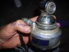
Figure: Hydraulic Housing Pressed Down and Circlip Removed
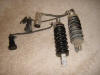
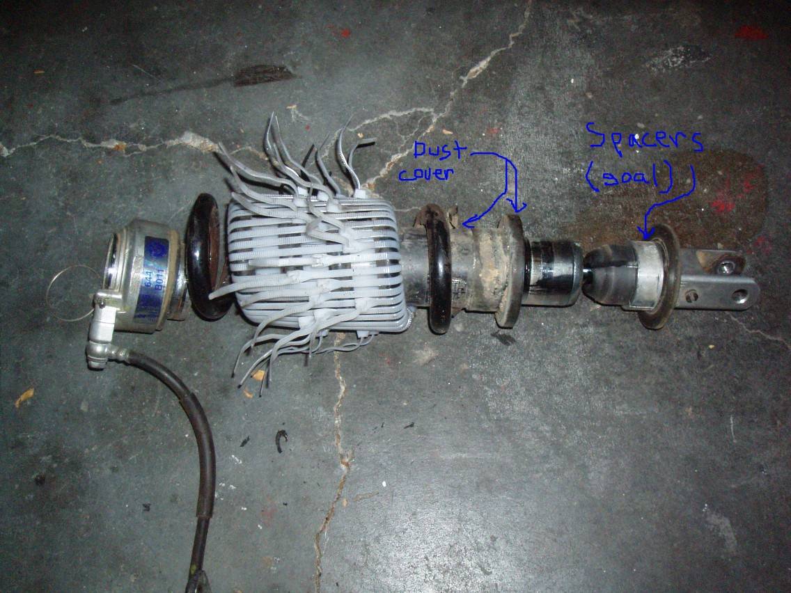
- Remove the circlip. Slide the hydraulic housing, spring, etc up
about 4 inches to get at the cursed shock travel limiter buried in the
other end of the shock. (pic 5)
|
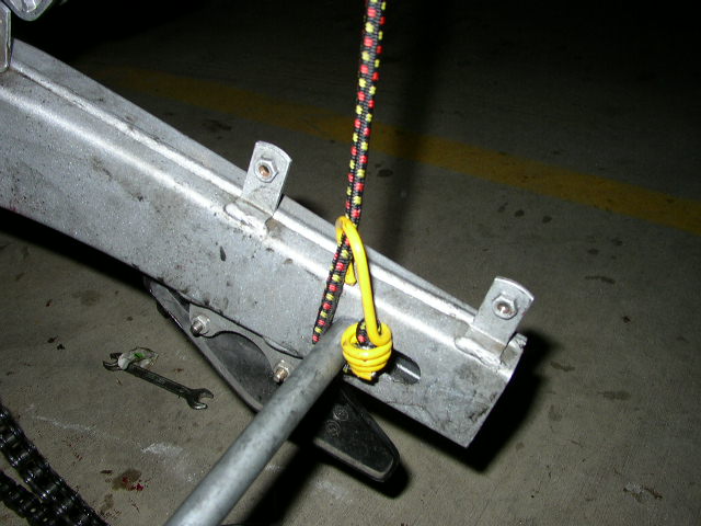
Note: Assembly is just the reverse of these steps. Be sure to
crank the pre-load back up to max before you start cutting the
wire ties, or the last few will rip out on you without warning!
Also, I found tying a string to the pre-load adjuster and
threading that through the bike frame first made reinstalling the
shock a whole lot easier.
|
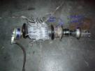
Figure: Exploded Shock Reveals Evil Spacers
Shock(ing) Problems (Q&A)
How do I know if the Rear Shock is stuffed?
First check your current settings as described in the
Suspension Tuning section before going
and shelling out for a new Shock, it may just be that you need to set it up
right for your weight and driving terrain (off-road bumpy, tarmac etc.).
Also don't forget it's not JUST the preload you have to crank up it's
also the S/H Screw (very sensitive so do it in increments) at the bottom
of the Shock. Although having said that a lot of folks have had their
shocks go AWOL at 20k miles. May want to consider stiffer
Front
Fork Springs too e.g. RaceTech, if you intend to ride 2 up a lot.
Generally:
- If you can't adjust the preload with yourself off the bike (bike
on centerstand), then something's wrong with the preload adjuster.
- When you ride with a passenger, you probably want the preload at
max and the rebound damping (the little screw at the bottom) set to max
(or close to max).
- On the stock shock, there's no compression damping adjustment,
unless you have a GS/Dakar.
- If your suspension is bottoming out on bumps or the rebound isn't
being controlled (pogo stick), your shock is toast. Mark #403
- If it goes clunk and drops down when you put it on the
centrestand it's probably knackered.
- If it goes clunk all the way up into the suspension well under
the seat, when you get on the bike, it's probably knackered.
- If (after you have set it up to what you think is about right),
it goes down quickly when going over bumps and just springs back up again
too fast ("boing") it is probably knackered. Kristian #562
Feedback (on stuffed shocks):
- First off, I haven't investigated
this myself yet. It's cold and gets dark too early (city dweller with no
garage!). The back of the bike bounces as if the spring is working without any
dampening. Bouncy bounce. I'm at 30,000 miles on a '99 classic F, and have done
no rear shock maint. I'll have time to work on this next weekend, but is this
likely to be a bad rear shock, could something be disconnected, or is there some
sort of fluid/adjustment that might take care of it? I didn't see any rear
shock-specific info on the FAQ site, so hope I'm not asking anything stupid :-)
I'm not riding it now, of course. Thanks for your input. BTW, I've never done
mechanical work before, and in the last 8 months of owning this bike, have done
lots of work on it because of the excellent info on this site. I'll join one of
these days... Stu Lincoln Park, Chicago
- 96 F650 with a pillion hard work!
I have a F650 which has 53000kms on it really good condition ,yesterday I went
for a 400km ride with my girlfriend on the back and got my arse kicked by every
one ,the bike was so weighted down on the back and light on the front,
particularly on up hill sections tarmac ,on the gravel it was okay but hard to
turn on tight corners . I think I need a new rear Shock but, 1 At 53000kms
should my shock need a replacement, 2 Would a new shock make a difference with a
pillion, 3 If I need a new shock what kind ,I l know a Ohlins is the way to go
but here they cost $1450, too much really might as well buy a new bike for that
sought of coin. 4 Can I fix up the shock already in the bike with a new spring
or something? Quasievil
- A seat that fits a backrest really helps with pillions too. Helps
em keep their weight where it belongs and can make the shocks behave too.
As well as the big pre-load tensioner I also adjust the small turn-screw
on the shock to a harder setting when I've got two-up. Sean
- You may want to consider having the hydraulic preload adjuster
rebuilt and a new spring fitted while you're at it. You have the
opportunity to match a new spring with your weight/riding style if you're
unhappy with the current setup. Removing the shock is easy. Take a look
and you'll figure it out. A bolt at the top, a bolt at the bottom, and a
small bolt holding the preload adj knob. You MAY have to remove another
bolt on the linkage at the bottom to get the shock off (can't remember),
but that's no big deal either. I believe the FAQs have a torque spec sheet
when you're ready to re-install. Mark #403
- I am trying to figure out if my rear shock is going bad. I checked
the FAQ but did not find my behavior in it. It seems like my shock is
changing ajustment without me touching the controls. The bike seems to be
increasingly riding stiffer like the preload keeps getting turned up. It
also seems like the hight of the bike is getting taller. Is this possible
or am I halucinating? What might be causing this? MasterITRIT #1231
- Usually a bad shock just loses its damping ability and your bike
begins to act like a pogo stick. However, with the hydraulic preload
adjuster, I can see that it might develop the symptoms you describe. Does
anything happen when you turn the adjuster knob? Any obvious problems with
the hydraulic line? Or is there any damage to the shock body that might
interfere with normal motion? Harl #380
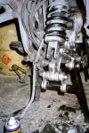
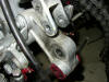
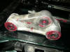
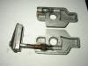
Suspension Higher After Service or Maintenance?
- If you find your suspension is higher after you perform a service
or have done some maintenance (that involved the suspension linkage), you
may have installed the "trangular" suspension link around the wrong way.
Have a look at this
picture from earlier in this FAQ (Suspension Linkage section) and also see
this
picture. Check to make sure the part where the shock attaches at the
bottom is around the correct way.
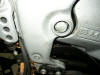
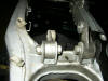
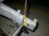
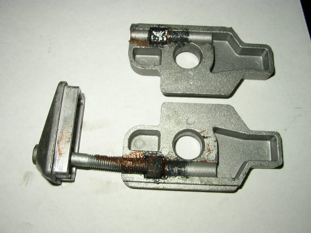
Bent Suspension Linkage Mounting Bolt?

Hello All, Just a note to let some of you more dirt oriented GS
boyz know to keep an eye out on the bottom suspension linkage bolt. Mine
was bent. Probably happened in Baja this last November. The pic shows the
bent bolt off of my 03 Dakar and the new bolt below it. Obviously, BMW
must have known there can be a problem as the new bolt has a long shank
with no threads to make it stronger. I am not sure when the bolt was
upgraded, but my 03 still had the older model bolt.
The reason I was even taking the bolt out, is that my Ohlins
shock crushed the rubber bushing in the top shock eyelet, so I was
removing the shock and found the bent bolt. This is what I get for trying
to keep up with two KTM950's in Baja. shafted
I have discovered a situation that I hope is mine alone but
thought it was worth posting as a heads up and to see what others may have
found. I removed the bolt that connects the rear shock knuckle to the two
dog bones (links). It is a grade 8.8 M12 x 110 mm hex head. I found it a
bit hard to remove. When I finally got it out I discovered that is bent
almost 1/4" from top to botton. The bolt is a FULLY threaded type.
I'm wondering if this is the same bolt in all the GS models?
Has anyone else found it bent?
I'm going to source a replacement tomorrow. If possible I will
order a PARTIAL thread bolt as it makes no sense to me to use a fully
threaded bolt in a place where the threads are in bearing with softer
aluminum links and where the bolt is subject to a lot of bending force.
I'll confirm with my hardware supplier but I think I can go to a better
grade of bolt too. Hopefully with a proper bolt it will have a longer
life. If you ride off road, have been known to get some air once in a
while or hammered the rear suspension on big ruts or holes you might want
to pull the bolt and check it. While it may only be bent and not break the
bent bolt is wearing parts out. I suppose it could introduce some friction
into the rear linkage but that may be trivial depending on how bent it is.
bg #1002
- See this
picture for the location of the bolt.
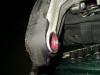
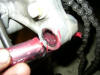
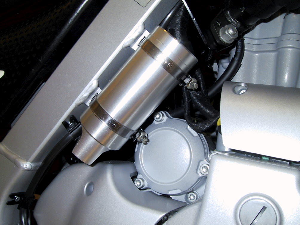
What do I do if the Remote Reservoir Breaks?
My girlfriend is a real brute: she broke again her suspension (the
second time on the trip!). This time, though, it's not the piston that
suffered: it's the little "bottle" on the side of the bike that exploded
(see this
picture - it's a F650GS Dakar 2002). The cap broke open and all the
oil leaked in a matter of seconds. Result: there is no suspension and we
are now stuck on asphalt... pierresas
- Is is possible to repair the bottle? What kind of oil should go
in it? At what pressure?
- If it isn't possible to repair, is it possible to install the
bottle from another kind of motorcycle (H*nda etc...)?
I looked in the semi-detailed BMW shop manual and the BMW ETK
parts program (fiche) but couldn't find an exploded diagram of the
reservoir. It appears that it's not a separate part from the shock which
is a real p*sser. The part number for the whole shock is 33 53 7 654 446.
It costs USD$502 (which is with a 20% discount from Chicago BMW). That
works out to PEN1769 (Peruvian Nuevo Sol).
If you're pressed for time, you've most likely already
concluded the quickest but most painful option is to just order a new
reservoir. Hopefully they'll have one on the continent. If you're not
pressed for time, you could call here in the USA to LIndemann's and see if
tehy'll provide technical assistance to muddle through the repair with a
reputable shock servicing dealer in SA. Or you could work out a priority
job with Lindemann's in California, USA but that would be awfully pricey
due to shipping. I do not have a number handy for Lindemann's but an
Inmate or two will pop up here in a bit and post the address for you.
And the last option I can think of is to replace the shock with
another brand such as Works otr Ohlins (pricey). NothingClever
#1441
How much play should there be in the rear linkage?
Clunking noise from rear shock?
I have a clunking noise that I have been trying to isolate and I think
I found the culprit. 99 classic F w/ 30K If I set the bike on the center
stand and rock it back and forth there is some play and accompanying clunk
in the linkage to the shock. so that each time it rebounds or before it
compresses there is some looseness that has to be takien up. is this
normal? paul smith
- In 30,000 miles have you or has anyone EVER lubed the suspension
linkage bearings? If not, you need to disassemble and lube the ones that
are still working and replace the ones that have been destroyed from
neglect. Flash 412 (CO)
My preload adjuster is stuck! Help?
My 2001 GS was too low and soft, so I started experimenting with the
preload adjuster and rebound damping. First, I could adjust the preload
very easily. It ended up at the "high" end. Then I adjusted the r.d. It
was set to a very soft position (all the way?), so I screwed it all the
way clockwise to the "hard" position, and rode to work. Now, the preload
adjuster is stuck in the "high" position.
I have searched the FAQ and the forum, and there is a rather depressing
comment in an old thread (4155). It basically says that I'm up a certain
creek without a paddle. Does anyone care to elaborate on this? What has
happened, how and why? And, of course: What does it take to fix it?
ThorH #1907
[Ed. note: Answers to this problem would be welcome!]
My preload adjuster is not clicking! Help?
Just picked up a 03 Dakar. Between weather cycles I've put 250 miles on
it. Really like the bike so far. Found this great site, and have been
cruising thru the tech faq's. When adjusting the suspension preload knob
it rarely makes a clicking sound. Maybe once every 4 turns if that.
Anything else I could check? Bgunn
- you lost your bb, dont worry about it. damalden #1598
- Don't worry about it if you can tell a difference in preload (it
will manifest itslef as ride height, most noticeable when on the
sidestand). If it doesn't make a difference, then the hydraulic preload
function is compromised and the shock needs to be serviced or replaced.
Good excuse to throw good $$ at an Ohlins unit. Mark J #1495
- Thanks for the info. When I turn it all the way down the ride
height increases. Bgunn
Will the shock from a 99 F650 fit on a 94 F650?
Will a shock off a '99 carb model F650 fit a '94 model? My everlasting
F650, Bronhilda, has now got 140,000km on the original shock! I have the
chance to buy a 5000km old genuine Showa part no 2 345 004 if it will fit,
for a lot less than new. I wonder if I will notice the difference??
DancesWithPoultry
- 140k! Outrageous Nigel! What do you drive on, Cotton Wool? I don't
know the EXACT answer to your Q, but I can check tonight (or someone with
an ETK can check soon) for you. Should imagine no change.
Kristian#562
- Yes Flash 412 (CO)
Will the shock from a 96 F650ST fit on a 97 Funduro?
- Same shock. It'll fit the funduro. Shank in Colorado #974
What is the part number for the GS rear preload adjustment knob?
- Apparently BMW sells only the entire shock assembly. However your local
Honda dealer might have the part. Some Honda VFR models use the same Showa
shock as the F650GS. Cost is reported to be around $40 US.
Can I use an Ohlins' shock from a Classic on my GS or CS?
- The consensus is no, not as it is. There are differences in lengths,
springs, gas pressure, etc. You would at least need to return it to
Ohlins' to be modified to meet the specifications for the newer bike.
However, members report the cost is nearly the same as buying a new
one.
Is my OEM shock missing the lower nut?
- No. The OEM shock does not have a nut on the lower mounting point (where the shock connects to the swingarm links). The lower attachment for the shock is threaded, and hence requires no nut.
Has anybody installed dakar links on a GS?
- The suspension links on a GS and Dakar are the same. The difference between the Dakar and GS suspension comes from the shock used.

 Here are a couple of other photos of the disassembled swingarm.
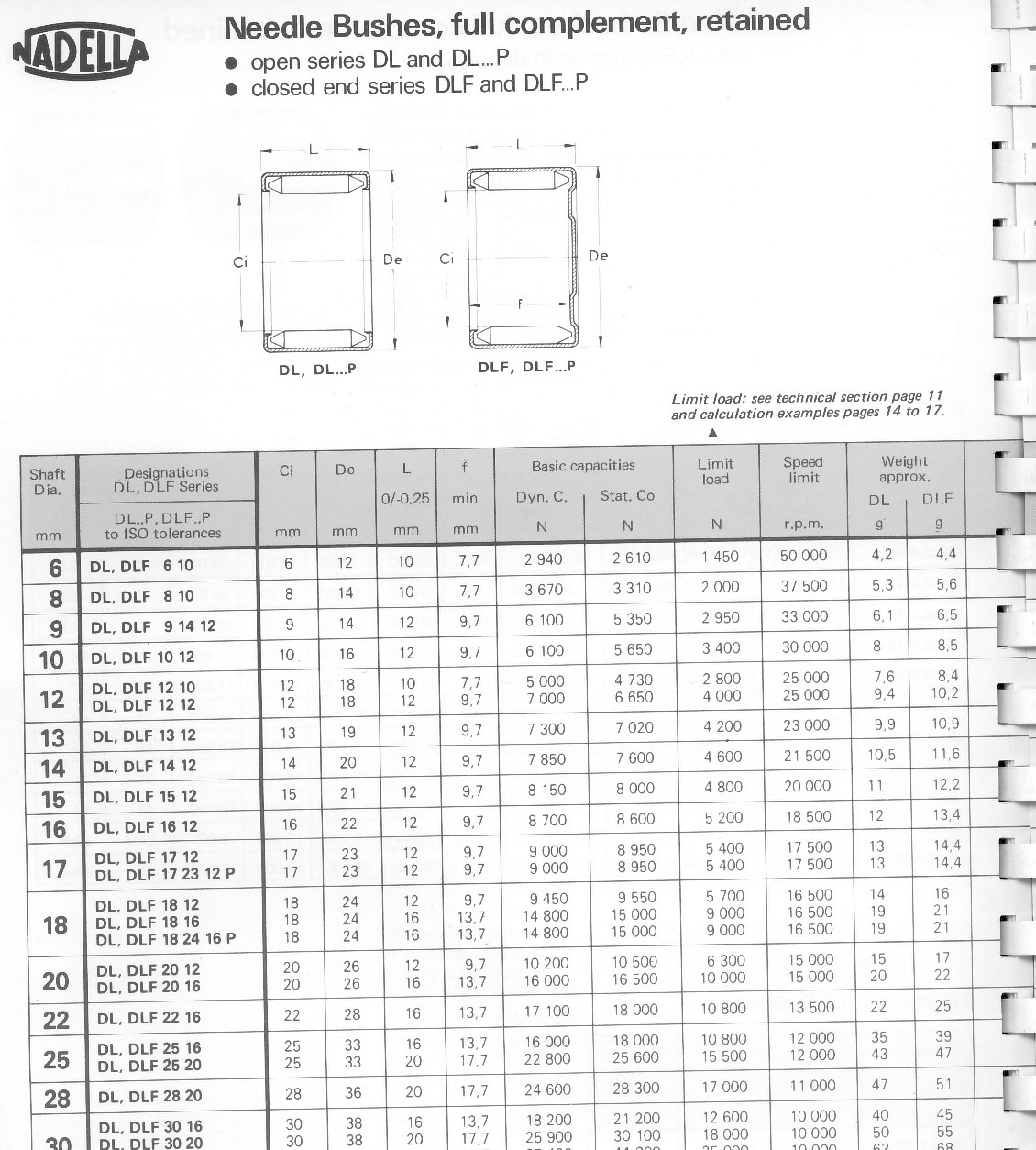
 1. While you are there, pop this chain roller off and lube it.
 2. Another shot of that upper chain roller/guide
 3. Swingarm, pop off the nut, drive out the swing arm pivot rod.
 4. Slide this pivot out.
 5. OK swingarm is off, note this seal on the inner and out of each side.
 6. This inner bush removes on the inside of the swingarm, note white
seal that wants to be lost.
6. This inner bush removes on the inside of the swingarm, note white
seal that wants to be lost.
 7. Lubed (no seal, no inner bush)
 8. Lubed, no seal, no bush
 9. Greasy fingerprints, bush installed with inner seal (a black
washer, plastic, that looses itself)
9. Greasy fingerprints, bush installed with inner seal (a black
washer, plastic, that looses itself)
 10. Since you are there....the lower "dogbone" of the rear
suspension needs some attention, take the few moments and DO IT! Still on
the bike (you can do this off the bike) the lower rear needles, not
grease that can be seen, inner bush looks ok.
10. Since you are there....the lower "dogbone" of the rear
suspension needs some attention, take the few moments and DO IT! Still on
the bike (you can do this off the bike) the lower rear needles, not
grease that can be seen, inner bush looks ok.
 11. After I get done with grease, messy messy, but hey, it keeps
things from wearing out.
11. After I get done with grease, messy messy, but hey, it keeps
things from wearing out.
 12. Removing the dog bone....
 13. Lubed, ready to install
 14. Back to your swingarm: Don't forget these suspension linkages!
They need grease too!
14. Back to your swingarm: Don't forget these suspension linkages!
They need grease too!
 16. Don't forget the upper shock bush which is a piece of junk plastic
sliding bushing.
16. Don't forget the upper shock bush which is a piece of junk plastic
sliding bushing.
 17. Since you are there...take the adjusters out of the swingarm,
clean them up, antiseize the threads.
17. Since you are there...take the adjusters out of the swingarm,
clean them up, antiseize the threads.


