The Aftermarket Lights FAQ
compiled & edited by Kristian #562
Please read the Disclaimer before attempting any work in this FAQ.
If you're looking for information on Power
Draw see Electrical Misc FAQs
&/or
Electrical Misc Qs GS
For Installation Tips &
Photos of Lights on the
F650GS/Dakar click the Link
For General OEM Information - Headlights, OEM
Bulb Installation Tips, Headlight Problems
For Reviews on Other Web Pages See
Lighting: Other Sources & Reviews
For More information on "How many Lights can I
run", "Flashers Don't Flash" and similar Q's see the Electrical Misc
FAQs
For Problems with the Rear Brake Light See
Brake Light
Before we start, a few
facts :
1. The stated output of the CLASSIC alternator is 280 watts.
2. The stated output of the GS/Dakar alternator is 400 watts. The FI type needs
more power to run its various electronics, but still has more to spare (unlikely
that you will ever flash the main beam, blow the horn, cycle the ABS, turn the
heated grips on at the same time). Andy #982
And a Word of Caution:
Some found that mounting driving lights close to the indicators makes the
indicators "invisible" to on coming traffic with the lights turned on.
BULBS
Replacement Headlight Bulbs
Generic Bulbs and Comments
-
I run a 100/130 W headlight with a 20W pilot light
to save the battery. If I run a weeks worth of short trips on the headlight (50
miles in 10 trips plus 4 nights and 5 days on the alarm), the alarm will get get
the battery down to 11.8V. You only get a couple of chances to turn the engine
at this power level. A 30 mile ride with the light and heated grips on still
restores the battery to 12.5 V plus. If you are doing short trips with the extra
lights you might want to get a smart changer and/or a voltmeter fitted. Andy
Leeds UK #982.
-
Driving Lights. You don't need to spend a lot of money. I got some lights with
great reflectors and H3 55watt Halogen bulbs for $19 at Auto Zone. (The bulbs
are the most important feature, IMO) They light the road just as good as the
PIAA, and a little better than the Motolights. (Their reflectors aren't the
best) I had to make my own bracket ($8) and wire my own relay and switch ($5),
but well worth the money saved. Michael #883.
-
Quartz halogen bulbs run hot, VERY HOT. There is a reason for that. The reason
is so that when you turn it off, the envelope ("glass") is so hot that the
evaporated tungsten settles back onto the filament instead of on the inside of
the glass. That is why H-4 bubs last so much longer than regular lite bubs.
Regular one turn yellow from the tungsten on the inside of the glass. The fact
that the tungsten IS inside the glass contributes to filament failure, too. DO
NOT TOUCH ... finger oil on the quartz will make a weak spot, leading to a
micro-fissure, leading to the loss of the iodide gas (a member of the halogen
family on the periodic table of the elements), leading to bulb failure. So do
NOT touch the glass of your bulbs with your fingers as you install them. Too
late? Use a little isopropyl alcohol to clean it. And use a tissue or cloth
between your greasy paws and the bulb. Flash #412 (CO)
-
I wore rubber gloves when I opened the package and placed the bulb. I was also
_real_ careful when installing the bulb not to touch the bulb. For that reason,
it may very well be worth it to remove the fairing for installing the bulb. it
is quite possible you will drop or accidentally touch the bulb whilst fiddling
blindly underneath the dash while placing the bulb. On my bike, the clip just
will not stay put; since I could not actually get in a place where I could see
under the fairing _and_ grab the clip, I invariably knocked it loose. The whole
thing seems like it would be just fine if that clip where somehow permanently
retained on the housing. Also it will be damn near impossible to not touch at
least something with the bulb as you insert it. A piece of greasy dirt or some
other scheme might end up causing the same effect Sir Flash mentions. NormJ #473
-
If I remember the clip fits into a set of retaining notches. To remove it you
push the clip like you are trying to clamp the bulb in even tighter, squeeze the
two ends towards each other to clear the retaining notches and then while
keeping the ends together you allow the clip to release past the notches. It is
possible to just catch one side of the clip in a retaining notch. I guess its
also possible to break the notch off, but it would surprise me. Installation is
the reverse of course. Chris in Santa Cruz, CA #782
-
I think Chris makes sense but I don't remember exactly how the clip fastens, and
it's almost impossible to actually see properly without taking the housing
apart. I'll try to take a look tomorrow. I'd have to admit that I have to get
the angle of my elbow and entire body exactly right to grasp the clip with my
fingers. I have to reach under the housing with my left hand even though I am
right handed. When you get it right, it should snap right in. I make a point of
orienting the new bulb in my hand exactly as I removed the old bulb. NO WAY I
could do it right handed, even though it's my better hand, as my fingers are too
large to get at the clip. Maybe there's a metal tab that is bent, or the spring
is bent. Possible your bulb was not properly seated? It only fits one way for
all the tabs to match, and then has to be fully inserted for the clip to catch.
Regarding the same operation in the GS, I have no idea. Todd #389.
-
I went to NAPA, Part number Wagner Lighting #BP1210/H4 for $12.00 . 80/100 watt
with no problems. Make sure you have a good clean connection w/plug & Clean
where base seats in housing. Don't touch the glass bulb it self or if you do
clean with alcohol & cotton ball. Dave #365.
-
A 100/130 draws exactly that on low/high. PIAA claim that their Super White
bulbs put out the equivalent of an 85w bulb, but draw only 55/65 watts. Even
still, those bulbs are listed as 55/65, since that's what they draw. I didn't
replace my 55/65 PIAA Super White ($34) with another when it burned out after
only one year. Instead, I used a Sylvania bulb that they claim is 20% brighter
than regular bulbs (same wattage). it was only $9 at pep boys and I couldn't
tell any difference from the PIAA. Mark #403.
-
The reflector does have an ENORMOUS impact, but a truly higher wattage bulb will
produce more light. Not a bogus higher-wattage-equivalent, ("our 55 watt bulb
makes 85 watts of light;" light is not measured in watts). I want to swap the
stock 55/65 for a PIAA 80/80, and the light output should be greater. I recently
swapped my car headlights 9006 55watt bulbs low beams for 9005 65 watt bulbs and
the light output is much greater (I also used low glare bulbs so as not to blind
oncoming drivers). Mason #631
-
I just looked at my 97. With my steering at full right lock I can see the bulb
and the white plastic ring it is locked into. The metal spring/clip pivots at
one end and its two ends hook into retaining notches on the other (riders right
on my bike). It is plastic, so it could break. New headlight? Chris in Santa
Cruz, CA #782
-
I think I saw (Andy) saying some time ago that a simple upgrade to the lighting
system would be to change the pilot bulb to 20w and the main bulb to 100/80 and
use the pilot for day-time riding. I just spoke to Motorworks and they say that
the 20w bulb will melt the plastic headlamp housing (maybe it’s just the pre
2000 classic). In any event they said that the 80 watt low beam used constantly
will not drain the battery. Pat#1210 '94 Classic F
-
Motorworks sold me the lamps and said they'd be fine! They were right, its been
run for 16000 miles or so with the same lamps and holders. The headlight is
130/100W and it does drain the battery if you are below 3000 rpm for any length
of time, you see it light up more when you rev the engine above idle. 100/80
might be better. I'd bet one of the new Motorworks guys is confusing the classic
with the GS. The GS has BMW not Aprillia wiring, so you can bet its cheap, nasty
and under specified just like the R series. Andy Leeds UK #982
Replacing HL Bulb pointers
NormJ #473
Okay, per mason 631's request, here is a brief set of pointers regarding
changing the headlight bulb. The reason this may be relevant to anyone is that
the little manual that comes with the bike fails to mention how satanically
nasty the little clip that holds the bulb in place is. If it were manufactured
with some kind of permanent mounting to the white plastic ring on the housing,
it would be cake; instead, the tight quarters under the fairing and the clip's
demonic desire to pop loose of its own accord make the job a hassle.
-
If you have the time and are _real_ concerned for protecting your new bulb from
being accidentally touched and/or soiled, go ahead and remove the fairing per
the FAQ. it will take longer but may be easier; you will have better access to
the headlight assembly.
I did not remove the fairing because one of the crush-nuts (or whatever they are
called) that holds my screen on is nearly impossible to reinstall. I am out of
valium and my allergy medication is preventing me from drinking the amount of
beer it would take me to calm down after the nightmare of reinstalling that
little bugger.
-
Pull off the 3-prong wire plug to the light. this may be easiest from below and
in front of bike.
-
GENTLY begin removing the rubber stopper that seals/protects the back of the
bulb and the reflector. do this by starting from the outside circle, gently
loosening one section at a time, moving around until the stopper feels "loose".
then gently pull it straight back. it has three slots that match the prongs of
the bulb. you can put your thumb on the prongs and pull back on the stopper, so
that you are not yanking on the whole assembly.
-
Now, take a peak at the retainer clip that is holding the bulb in place. It is
evil. Learn to fear it. It is released by pinching the two right ends together
so they both release from little hooks to which they "stick" due to the spring
action of the clip itself.
On the left side is why the clip sucks. When the tension of the clip is
released, it wants to move left and back, thus coming free of the "notch" in the
white assembly that holds it. It is reinserting the clip into its left side
"notch" that is keeping anti-anxiety drug makers in the black; it just doesn't
want to go back in _and_ stay in place while you close it over your new bulb.
SO TRY NOT TO DISLODGE IT FROM THE LEFT SIDE NOTCH!!
Gently squeeze the two right ends together and keep tension towards the right of
the bike as you try and swing the clip open.
-
Try to do as little jostling as possible when you pull the bulb out. It should
come straight back and out. You are quite likely to knock the clip loose right
here. If so, savor the moment and trot-out those seldom-used curses you keep
filed away for special occasions. Stick the new bulb in keeping the same
caution. I found this process to be easiest from the right side of the bike,
with the bars turned full left.
I wore rubber gloves and moved wires out of the way to keep from fouling the
bulb glass.
-
If you haven't dislodged the clip by this point, run out to the nearest 7-11 and
buy a lottery ticket. Otherwise, turn the bars full right and stand on the left
of the bike. Insert the clip's mid-section into the notch and push it right
until you hear it "click". This is easy. What sucks is not knocking it loose
while you try to close it over the bulb. I did this by clicking it in the notch,
then while still on the left side of the bike, gently folding it over the bulb
until it was fully in place but not clipped.
-
CAREFULLY turn the bars full left and move to the right of the bike. While
pulling the clip towards you (to the bike's right), pinch them together and push
them forward until they seem to fit in their proper place. Then release them.
For me, it took about 5 tries for this step; when it finally worked, it was by
allowing one side of the clip to seat first, then doing the next. And in the
meantime the clip might very well pop out of the left side of the housing
-
I cleaned the prongs on the bulb and the socket at this point.
-
Reinstall the rubber gasket with the utmost in care.
-
Put the plug back on.
I sincerely hope that my technique was just dumb-ass from the beginning and that
no one has ever or will ever have the same problems changing the damn bulb.
UPDATE:
A few months back I posted an anguished account of my severe difficulties
replacing the head lamp bulb. the stupid clip kept coming off and was impossible
to reseat. Some joker replied that s/he had zero trouble replacing bulb and that
it took only 90 seconds to accomplish. I wanted to track that inmate down and
fill their gas tank with bud light. try running your bike on that schwag. Well,
parked on the grass in the windy plains of S.D., I replaced my headlight bulb in
about 97 seconds with no hassles. That damned clip stayed put no fuss no muss.
Go figure.
Rewiring the High Beam?
Q. Has anybody rewired their high beam so that the low beam stays on when
you turn on the high beam? Testing with that little high beam flasher switch
seems to indicate a lot better overall light coverage with this setup. Hard to
do? Good? Bad?
-
The heating effect on the lamp will be interesting. Andy Leeds UK #982
-
Not sure it's a good idea. In addition to Andy's comment, the load on the wiring
and switch might be a bit of a strain. I'd consider using a heavier ground wire
on the headlight plug also. Todd #389
-
Seems to me some folks had issues with the 100 watt high beam bulbs melting
stuff. High and low together would be 115 watts and even hotter. YMMV. Harl #380
Headlight Plug Meltdown
-
The same thing happened to me last month on a 99 F650 while I was riding on
I-580 in Richmond, CA at night. The plug was too far gone to fix and I had to
have the bike towed. I agree with Randy that this is another area like the
original chain, seat covers, etc. where BMW skimped on the quality of
components. The next day, a local shop (City Cycle Werkes in San Francisco)
soldered another better H4 plug on for $35.00. Kale #557.
-
I found a melted plug when I bought the used 1999 model. The bulb had been
replaced with a larger wattage lamp, and I'd guess that was the problem. Dealer
replaced for ~$40.00 including the part, Joeg #1102
-
If you never had to mess with the headlight bulb before, it's possible that the
(otherwise perfectly good) plug eventually vibrated loose over the years and
made poor contact, finally overheating. That's one plug I make a point of
pushing on regularly to make sure it's well seated. Because it can get wet, it
doesn't hurt to make sure it has a drop of grease or lube to prevent corrosion
also. Todd #389
-
I'm away on a weekend trip when the hi-beam indicator light comes on during the
middle of the day... drat! But, being prepared, I'm carrying a spare bulb so I'm
not too worried. When I get to my destination and reach under the dash to swap
out the presumably burned-out bulb, however, I found instead that the plastic
plug that connects to the three light bulb prongs had melted down on one side.
So, it's not the bulb but the plug that is the culprit. I was able to get the
headlight working again by using electrical tape to patch the suspect connector
back into place on the plug, but I'd like to fix and get to the root of the
problem. Any idea what would make one of those little metal connectors in the
headlight plug overheat like that? I checked the FAQ and didn't see anything
similar addressed. Also, does anyone know the part number and cost for replacing
that little plug? Even better, does anyone know of a lower-cost alternative part
in case typical OEM pricing is in effect? Ken #784
-
Typical cause is (A) overwatt aftermarket headlight bulb, or (B) poor headlight
bulb/socket connection (corrosion or loose connector). Both conditions end up
pulling more current than the wiring/socket is rated for. Get a H4 replacement
headlight socket at Pep Boys, NAPA or equivalent car place. Marty #436
-
Believe what you want, but shorted cheap plug, made in China (probably) or some
other third world country is culprit. Ground and hot wire have mated,
surprisingly without blowing fuse in process. Who the hell wired these bikes
without fuse circuit for headlight? I'm guessing about missing fuse, but fuse
would go way before socket meltdown, if one were in same line! Randy748
High Intensity Discharge
(HID)
See
HID by Will England for a good review.
-
There is a lot of discussion about lights: adding aftermarket lights, increase
bulb wattage, fabricating or buying light bars, PIAA's, Hella's , Motolights and
the like. What about HID? More light with less wattage. Very durable because
there is no filament, and long lasting bulbs. I have a friend that did a
(HIDS4Less) conversion on an RT and he has nothing but positive comments about
it. Any feed back would be appreciated. Steve#1059
-
There was a recent post about putting HID's on a VFR on VFRDiscussion.com. The
poster included before and after photos. The light was way brighter and much
whiter. BUT, you have to put very large ballists somewhere to get the lights to
work, and the cost (without labor) was over $1,100! The ballists are about the
size of two CD cases stacked up. Larry
-
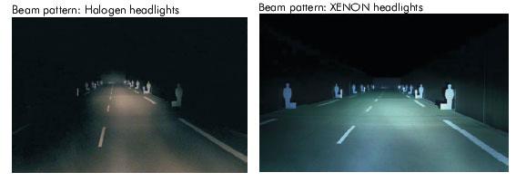
Here is something from Baja Designs' site: What is HID. The HID bulb uses an arc
of light similar to high intensity stadium lighting. Unlike stadium lights,
however, this new lighting system uses extremely high voltage (18-25 thousand
volts) to initiate the arc so that no warm up time is required. It produces a
light measuring 4100 deg. Kelvin compared to 2800 deg. Kelvin produced by a
typical halogen filament lamp. The results are a daylight white/blue light that
produces more than 3 times the amount of lumens as compared to halogen light,
while consuming only about 50 watts of power. Once the bulb is up to full
brightness (about 1 second), the controller then provides a steady 90 volts to
maintain the arc. HID lamps use a controller and igniter to provide the very
high voltages needed to start and maintain the HID plasma arc. HID lamps produce
daylight quality light and brightness, far outperforming conventional quartz
halogen lighting systems. Without the use of a filament, these lamps fire an
electric charge at 18,000 volts between two electrodes encased in a xenon gas
filled bulb. The results are revolutionary, consuming much less energy,
significantly reducing heat generation, yet providing outstanding brightness and
durability. This is great news for motorcycles, because typically they don't
produce all that much lighting power to begin with, and because the bulb has no
filament, vibration is not a detriment to its operating life (2000 hours). Baja
Designs has a site with good info on HID lights. Here's a turnkey product for
$450. Flash 412 (CO)
-
Pseudo HID light bulb: Some time ago I've bought two "fake" cheap HID H4 bulbs
that were advertised on EBay. Not the same, but very similar to the one
advertised here.
The bulbs had a higher wattage than stock (100/80W, I think, versus 60/55W of
the stock bulb) and my idea was to replace the short life expensive PIAA that
the previous owner had left in the bike. Somebody asked me to post my
experience, and here it is:
Lifespan:
The first of the two, burned out after two weeks or so, the other survived more
than a month. I haven't used the bike since then and the bulb is still there. I
don't believe they last much. But it seems that the PIAA have the same problems
with the difference that these bulbs are $10 a pair...
Battery:
At that time I installed the bulb, I was commuting 20miles a day and because of
the short trips I didn't realize that my battery was overcharging and drying out
because of the higher wattage (see the FAQ for a solution to this problem). When
it was time to head home and I started riding 15h/day the battery became a
problem and I had to refill the cells every day, but I managed to complete the
trip. Being on the road, far from the FAQ and having done OK with the bulb on
commuting trips I failed to find correlation between the overcharging and the
new bulb. Mea culpa. The fix on the FAQ should solve this problem.
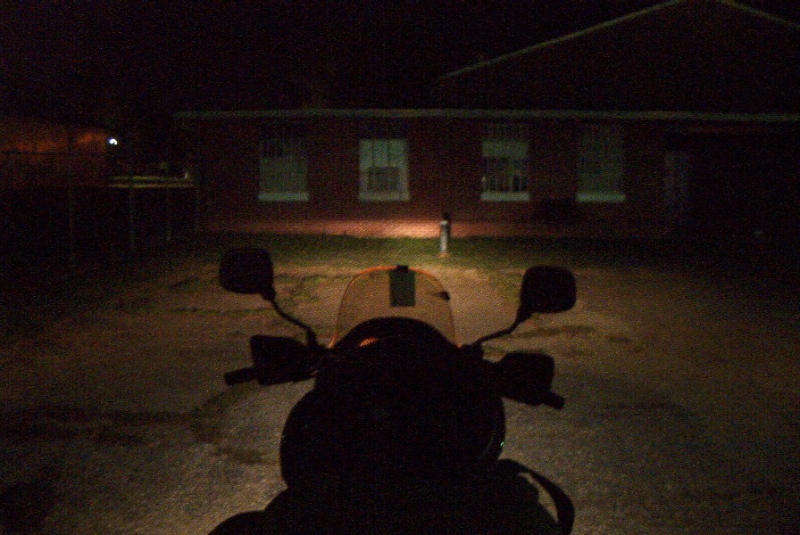
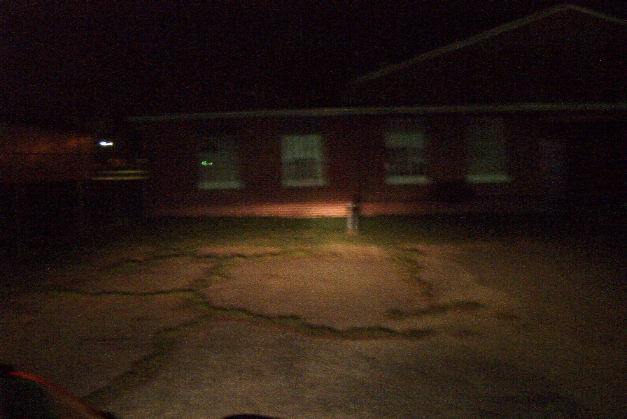
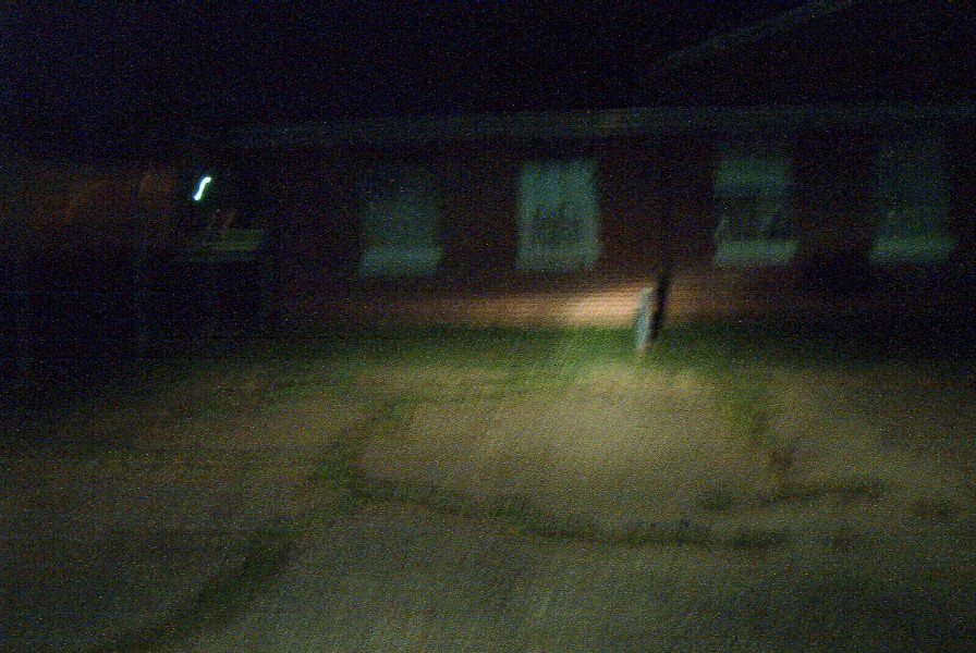
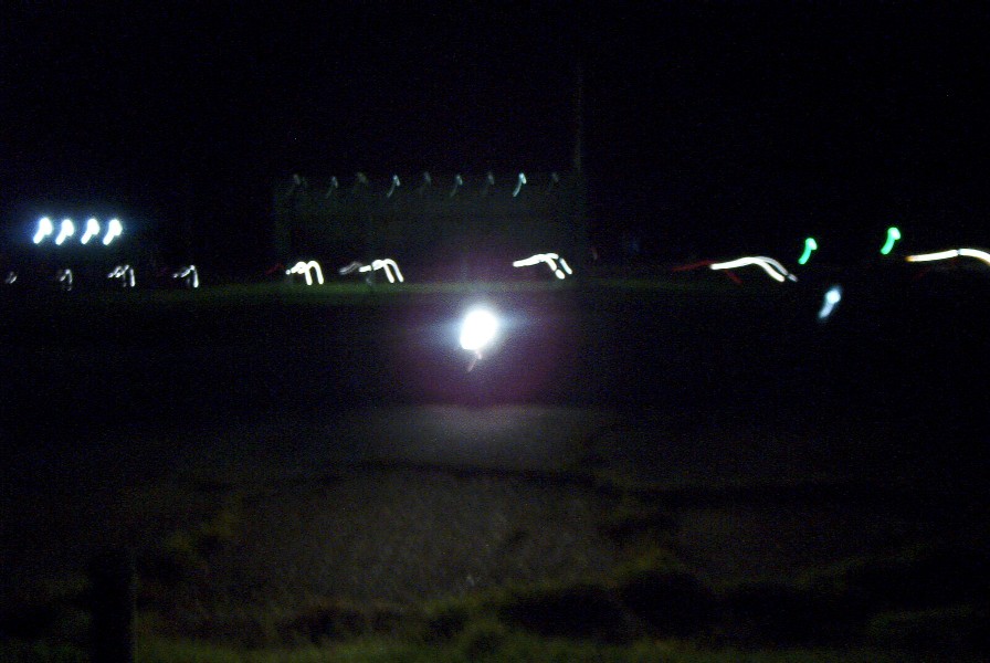
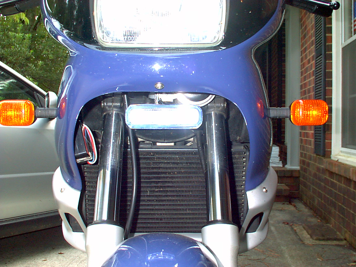
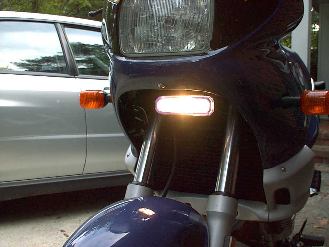
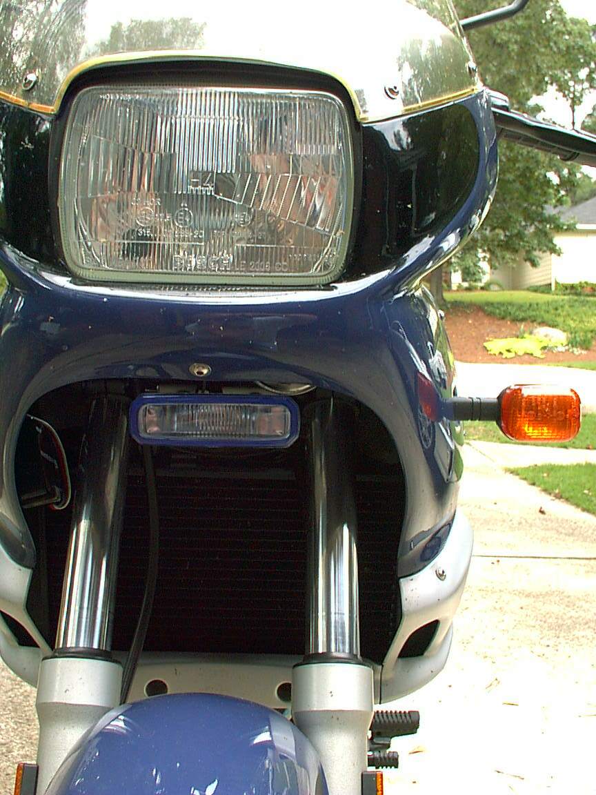
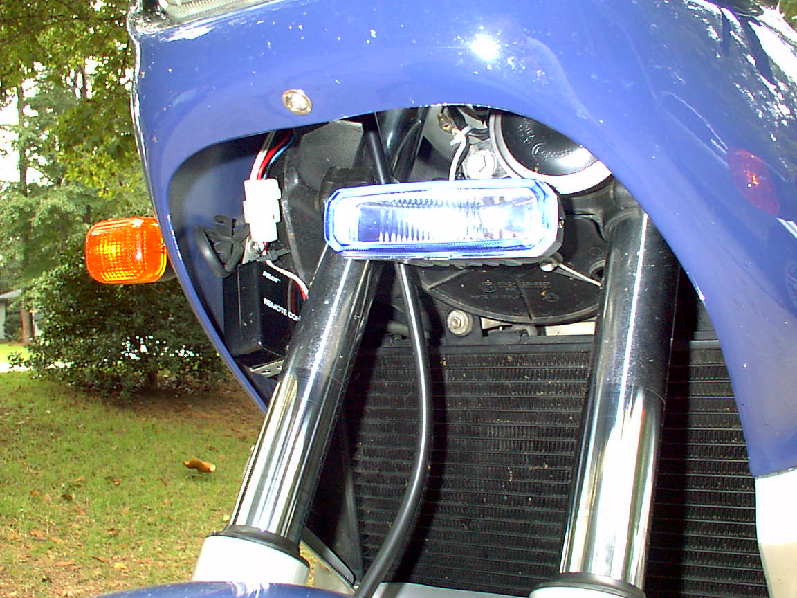
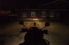
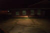
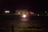
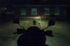
Visibility:
The whiter bulb IS more visible and give you the "impression" that you see more.
These pictures were taken without flash, with a digital camera and they don't
show much difference (in particular given the difference in Wattage), BUT what
your eyes see IS different.
|
Philips H4 bulb
(60/55W) |
 |
 |
 |
|
"Pseudo" HID
Plasma bulb (100/80W) |
 |
 |
 |
On the highway, having the impression of a better illumination AND being more
visible may be of some advantage. Personally I felt safer and more comfortable
riding at night. However, I had a terrible experience when going off road. In
the same evening I was almost falling three times. The reason is that the light
is so powerful that it blinds you when you look at objects that are too close.
In the dirt I had to look for holes and stones close to the wheel and with that
light it was almost impossible to have a good visual (Well, I could have slowed
down a little, but this is beyond the point of this discussion....).
Conclusions:
I had enough. As soon as I get the bike out the winter storage (still snow in
Boston) I'll remove the bulb and switch to the Philips. If anybody is interested
in doing more tests, the bulb will be available FOC. BUT I am thinking to give a
try to whiter bulb having stock wattage... gim '97 F650, Waltham,
MA.
-
I also think a lot of H-4 housings are made of plastic that won't handle the
heat of HID bulbs. One reason the conversion kits cost so much is the housing
needs to be replaced. David #476, '99 F650.
-
Next.
PIAA
-
I changed to the PIAA Extreme White bulb--a bit costly but does seem to improve
the light and draws the same power as stock. Others have done this also and it
seems to work ok. Bill No.391
-
I changed to the PIAA almost right away. I'll echo Bill in L.V. seems to be
better and a bit of cool purplish blue tint. I went with the HID version, bought
it at the dealer for like $45. Have fun getting in there to change it, will take
a bit of patience (least it did me). I was the moron who didn't unscrew the
fairing. Duh, that's why I was out there for a half-hour changing that thing. I
was very proud of my dexterity though. Colbster of So Cal
-
My PIAA Super White seemed whiter, but I don't believe it was actually brighter.
the $32 bulb lasted 1 year. My PIAA auxiliary driving lights light up the night,
a whole other level of brightness. but whether or not the charging system can
handle the extra load with long term use, I don't know. I only use them
occasionally when I really need them and I've had to replace one voltage
regulator after 3 years. Mark #403
-
I recently replaced a Philips 60/55watt for a PIAA 80/80watt and have found the
difference to very noticeable, both day and night. Some people have been using
100/130watt bulbs without problems, but I didn't want to risk that. And if you
unscrew the fairing (easy, see the FAQ), changing bulbs is a snap. Mason #631 -
97ST
-
Hate to say it, but my PIAA Super White burned out pretty fast. I have the
original back in. Chris in Santa Cruz, CA #782.
-
Flash was right-on about the $45 PIAA replacement bulb. First, it was whiter and
brighter at short range; i.e., it lit up signs better, but at 70 mph at night I
was dangerously out riding even the high beam. my friend's $9 Napa special cast
a beam at least 40% farther. Second, the low beam filament pooped the linens on
me after just 9 weeks. And it died in heavy fog and rain in southern mn ...
folks were clicking their lights at me and I had no idea why (deer up ahead?
speed trap?) until I leaned over the bike and noticed no headlight. (it worked
when I pulled out of hotel 1 hour before). Rode under high beam to a mom-pop
parts store and for $8.05 out the door I replaced it. If you are considering the
PIAA bulb that is marketed as twice the power of the stock 12v 60/55, I suggest
you buy a NAPA special and spend the rest on beer ... it would be safer.
-
I've mentioned way before this post that switching
headlight bulb only as an alternative route to take. I DID and have no problems
with TON more light than stock. 100/130 is what I use (PIAA bulb) and it has
provided nearly the light of add on PIAA's. I've had both and have the
experience of the add-ons and have no problem with the light provided by my
single bulb switch over. Some have mentioned heat as a danger to higher 100/130
wattage, but you have to prove it to me. Mine stays COOL to touch. I'm not just
touching the glass, but reaching behind and touching the reflector and plug in,
where one would expect more heat and damage, "if" it were to occur. No heat on
my '99 model! One year without any problems and no comparison to stock headlight
and a much simpler solution than the expensive add on PIAA's. The PIAA bulbs are
not cheap either, at 40$ US. My 100/130 is PIAA. Randy748/Calif
-
When I got my F650 last year, I dropped in a PIAA
replacement bulb in the headlight. It is WAY more bright than the stock bulb,
and is a "cut-and-paste" replacement. I think it was about $35.00 Highly
recommended -- especially if you do any night riding, and there's nothing
sticking out the sides of your bike or to shear off when you go off roading.
BillW#930.
-
I have already installed them. They look OK to me, brighter than the Sylvania. I
think the beam has a different shape, but I am not sure. Hi doesn't look much
different from low. I don't have time/tools to do a better comparison now. Don't
know how long they will last, but anyway, they are cheap (and with 1 yr
warranty). gim (orange '97ST)..
-
Flash was right on PIAA bulb. Yep mine burned out in about the same time frame
maybe less on the low beam only. Expensive lesson now I run a 10.95 special from
"other guys" that puts out the same light, maybe more. Hey live and learn right!
tom1089 s.c. pa.
-
I replaced the stock headlight bulb with a $40 PIAA a little while ago. This
evening I had dinner with some friends and noticed that my low beam had burnt
out. Doesn't like it lasted very long. Do PIAA bulbs normally have a high price
and short life? I really noticed a big improvement with the PIAA but can I
afford the $40 every couple of months? What other alternatives have any of you
found? Dave # 717
PLAZMA XENON BULBs
-
I'd say stay away from them. The blue lights are a bit of a sham in that
they claim to get more light output from the same wattage, but, in reality, you
get less light because these bulbs are painted blue - putting a filter on the
light is just going to reduce output. If you really want the blue HID look (you
could argue that they increase conspicuousness), then don't buy some no-name eBay
offering - buy from a reputable manufacturer as quality can vary greatly. The
add you reference is full of half-truths and misleading statements anyway. Stay
away from the temptation to use a higher wattage bulb as well - unless you are
prepared to add heavier wiring and a relay. Even then, your
housing/reflector/lens may not be able to take the additional heat. The
consensus advice for better bulbs seems to be Philips Vision Plus. You can buy
them here. Of
course the only way to get a significant amount of additional light on the road
may be to add auxiliary lighting. Here are a couple of good links for you that
debunk the 55W=80W, etc. BS:
Link 1;
Link 2. MichaelC #941
-
MIchealC's advice is good and his comments are accurate. Blue "HID look" bulbs
are a complete waste, and the Philips bulb is widely considered to be excellent.
While several Inmates have been using higher wattage bulbs (as high as 100/130)
with no problems, you are taking a risk. If you want a blue-ish bulb that is not
heavily filtered, and are comfortable running an over-watt bulb, check the PIAA
bulb link below. The PIAA bulbs should be better quality than the no-name bulbs,
the output should be significantly greater than stock, they are blue, but not
extremely so, and at 80/80 watts should be less risky than higher wattage
alternatives. Mason #631.
-
I tried something called "Xenon" 80/60w (or similar) but supposedly much
brighter and with a hint of blue (the blue is what I wanted, to be better seen),
though around here people print whatever they like on packages, and it *did*
melt my socket. Stick to well-reputed manufacturers. Aleksander in Dubai 98ST.
Philips Vision Plus H4 headlight.
-
The 650GS has one H4 bulb (dual intensity for hi/low). There is a second smaller
bulb that serves as the parking light. I'm using one now. They sell them in
packs of two so you'll have a spare or one to sell. BradG 1002
-
Same on the classic. one dual filament headlamp, one 10 watt parking lamp. Mark
#403
-
I've been running one in '99 classic for several months now w/out problem. I
didn't notice too much difference. It's a bit brighter, but nothing that would
knock you over. Then again, I've got a set of PIAAs which I use frequently so I
may not be in the best position to judge. T-boy #456 (Wash., DC)
-
I've had the Vision Plus H4 in my '99 Classic for about six months now with no
problems. It is noticeably brighter than the stock H4 bulb. Bob#550. I use a
Philips "Vision Plus" H4 bulb in my '99. It's noticeably brighter than the stock
bulb, but draws the same current. I thought changing the bulb was easy. I've no
experience with PIAAs or Motolights. Bob#550 (Olympia WA).
-
I have used Philips Vision plus and they are much brighter. Here is an online
site to order them. These guys are good and fast and no shipping charges.
http://www.autolamps-online.com/halogen/index.htm. Dick #420
-
These bulbs are only sold in pairs, and I just ordered a pair, so if you're
still in CT I'd be happy to sell you one bulb for half of my cost. Just so you
know, they're not DOT approved for use in the USA. James #523 CT
-
This is the one I use:
http://www.powerbulbs.com/pvph4.htm. Jason#1027 UT
-
I also have the powerbulb, and like the extra light. It does fit a bit loose in
my housing, but that has not been a problem. 99 classic. Paul #813.
-
I have used the 100/130w H4 bulb inn my 99 Classic F650 for the past 6000 miles
or so. I live in Eastern PA, the temperature here is up to the mid 90's this
summer, I took trips up to 4 hours of continuous city traffic riding with the
headlight on low beam all the time, never melted any wires or plastic housing
for the headlight. Cat0020 in PA #1056.
-
I use Phillips "Vision Plus" bulbs and really like them a lot. You can get them
from http://www.powerbulbs.com and if
you tell John you're with the chain gang, they might still give you a special
deal. When I got mine, I got them shipped from UK to USA for free. Another plus
is that they come in pairs, so you have one for another bike (if you have one)
or you have a spare. David #476, '99 F650.
Auxiliary Light FAQs/Installation & Mounting
Reports
PIAA/Motolights/HELLA FAQs
Q. How do I
install them?
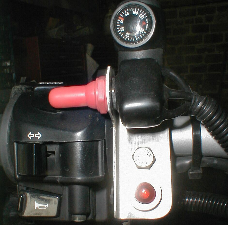
I'm putting the PIAA lights on my '99 F. The instructions say I need to find a
wire to tap in to to be a power source for the switch. Suggestions? I don't have
a voltmeter or wiring diagram of the bike.
A1. I connected it to high beam positive wire. Marko
A2. If you use the high beam tap, you will only be able to run the PIAAs
with the high beams on. The benefit to that is being able to control the light
with the high beam selector (i.e. left thumb). the downside is you can't run the
low beams and the PIAAs. I added a second switch during my installation as an
afterthought. It's a three-line water-proof switch mounted in the dash. The PIAA
relay input goes to the middle line. the other lines are connected to the
parking light (my original tap) and the high beam. using this switch allows me
to run the PIAAs regardless whether high or low beam (by setting the switch to
the parking light side). It also allows me to control the PIAAs by the high beam
selector (by setting the switch to the high beam side). this setup gives you the
most flexibility AND convenience when riding the back roads. makes it easy to
shut down the PIAAs and high beams simultaneously for oncoming traffic, but also
allows for lane splitting with the PIAAs and low beam. Mark #403.
A3. I ran mine back to the fuse box under the seat-- to make it switched
with the bike and to keep the wiring organized and logical. I put an inline fuse
about 6 inches away, also under the seat. My switch is a very neat OEM-looking,
weather-proof toggle switch through the dash, between the gauges. Jo' in NJ
A4. The parking light positive lead is a popular choice and
recommended in Cyclegadgets instructions. A word of caution, however: If you
inadvertently turn off your ignition to the park position (thereby turning on
the PIAA's), and don't notice that you've done so, it won't take long to run
down your battery. Also, I've forgotten to turn off my PIAA's in stop-and-go
traffic, and have needed a push to get started. Cary in Vancouver.
A5. Relays and driving lights. I installed my driving lights several
weeks ago, and I ran a wire from the hi-beam to my lighting relay: this wire
triggers the relay which then has my driving lights go on and off with the
hi-beam. This has worked very well so far. But Natalie recently posted a comment
about having the driving lights on with the low beam by using a 3-way switch.
Since I don't drive much at night in busy traffic I never worried too much about
that. But winter is here, and last night I ran an errand on the bike, and of
course city traffic was busy, and I felt obligated to keep my hi-beams off. I
felt pretty invisible with my yellowish driving lights off: I've been told by
friends that they REALLY stand out in traffic. Scott, ID #1244
A6.
1- Get yourself a voltmeter or Digital Multimeter if you can.
2- diagram of the H4 plug/bulb from the driver standpoint:
low beam
____
| |
| |
ground high beam
(green)
I tapped the high beam, added an inline fuse at the battery + lead, and a
waterproof two-post switch to disengage the entire system if needed.
3- Of course you are using a relay and new wiring for the supply leads instead
of the existing wiring, right?
In Summary, Clockwise from left vertical post: Ground (brown), Low (yellow),
High (white). The arrangement is logical. Jason#1027 UT
Q. Do I
really need a Relay?
Q. I just added 110 watts of lighting to
my '02 Dakar. Hope my battery can survive it. I wired the halogen "Rally" lights
to the hi-beam wire just before the wires enter the headlight. Doing this, the
additional lights come on with the high beam, and off when on low beam. I may
add a switch to allow me to turn them off completely if desired. My question:
Will I overload the original headlight wires by essentially doubling the amount
of draw through them?
A. Short Answer If you didn't feed the new light with a
relay, YES, you are likely to melt down your wiring or switch shortly.
-
I would
use the current from the tap you made into the high beam wire to activate a 12V
relay then use a separate circuit to provide power to the relay and on to the
auxiliary lights. this will prevent overloading your wires and your high beam
switch and still allow you to integrate a separate switch into the circuit
between the high beam wire and the relay in order to deactivate the aux lights
and still be able to use the high beam. relays are cheap insurance against
future electrical problems. Randy.
-
Not
knowing the wire gauge and amperage load, hard to say if it can be drawn through
the system. I agree that most often wiring to the relay output instead of thru
the signal wires makes for greater load carrying ability. This is due to the
wire gauge being heavier thru the relay. whitefish 02 Dakar Idaho.
-
One
suggestion is to tap into your hi-beam wire to run the relay. Relays are so
small, the extra load won't hurt. Since you don't want the extra lights to come
on every time, add another switch as noted below. Ground the other side of the
relay.
This will probably look like crap but here goes.
tap into
hi-beam switch relay
-----------------| |--------------( )-------------- Ground
battery-------------------------||--------------- Your Lights
Depending on the relay, you'll get a normally open contact or two. Maybe even a
normally closed set of contacts. That's what I mean by || above. The relay will
be real small but essentially, it's a coil that closes the contacts when the
relay is energized. For 110 watts, you'll pull around 9 amps. Make sure the
relay contacts are sized at least for that along with the wire too. Take one
side of the normally open (N.O.) contact and wire it straight to the battery.
Wire the other side to the lights. When you hit your brights and the switch is
closed, the relay will energize. When that relay energizes, the contact will
close and supply power straight from the battery to your lights. That will give
you a nice bright set of lights. I didn't show fuses in any of the circuits
above.... you'll need them.
-
I can
tell you that I have been running a 110 watt headlight for 17,000 miles without
a problem. The bike is designed so that if you have too much draw you will blow
the fuse long before the wires melt. The extra light really helps. Stuportech,
Dakar.
-
If you
are advising Scott that he can run 170 watts (110 + 60) thru his headlight and
switch wiring, IMO you are misleading him, unless the wiring in the GS/D is more
substantial than the wiring of previous F models. Todd #389
-
No just a
110 watt H-4 head lamp is about max for this system. If I miss read his question
I apologise. I am a tech not a reading specialist I am afraid. Clearly 170 watts
is too too too much. Extra lighting takes extra stuff just like you get with
PIAA kits.
-
I bought
a separate relay, and wired everything per its instructions. The only thing the
original headlight wiring is doing now is triggering the new relay to activate
the new lighting; the new lights have their own wiring, fuse, etc. I will need
to add up my watts, and see how close I come to 400 watts max if I add heated
grips and a vest. Scott
Q What about Alternatives
for Mounting them?
For Installation Tips &
Photos of Lights on the
F650GS/Dakar click the Link
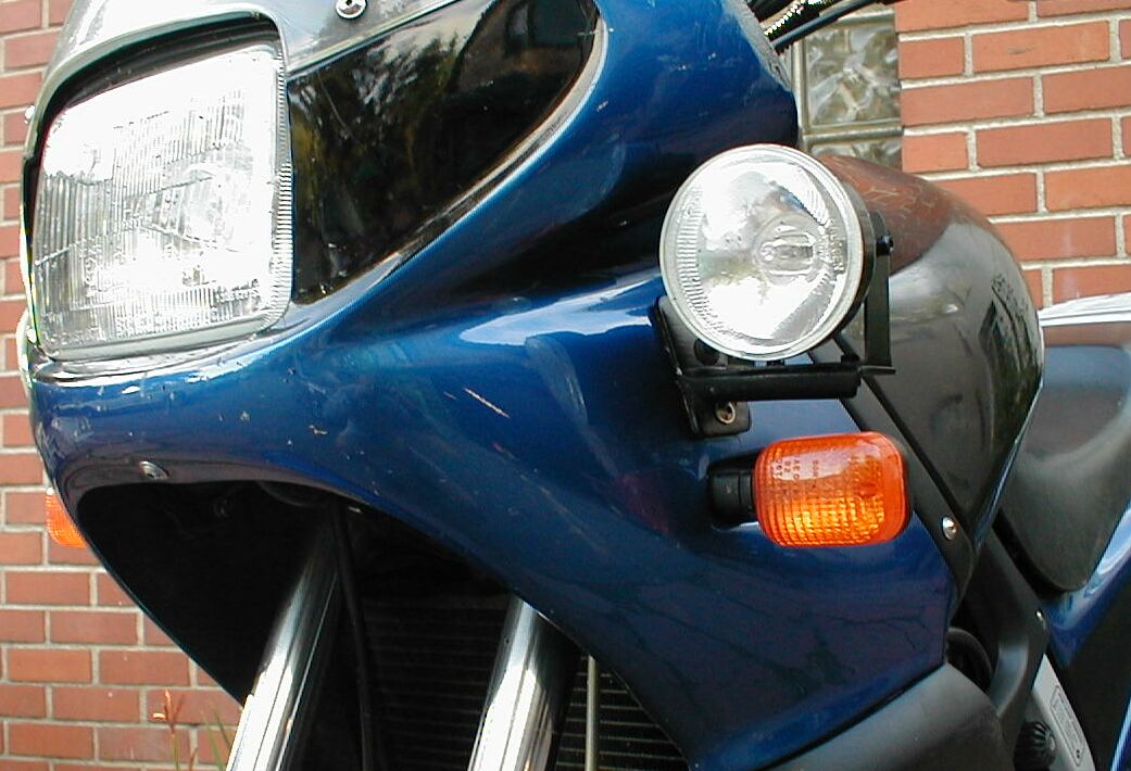
When installing the lights bear in mind NOT to
put them too close to the turn signals Here's Why:
-
Headlights + Turn Signal. While caging it the other day, I faced two different
motorcycles stopped, waiting to turn left with turn signals on. Both had
multiple headlights at the same level as the main headlight, and in both cases I
had to concentrate *really* hard to see that the turn signal was really on - the
brightness of the headlights reduced the visibility of the turn signal - due to
their proximity? It was daylight. Sounds dangerous to me . . . had I not been a
rider, I probably wouldn't have even bothered to look. Muriel #582
-
Good
observation. Many people install a higher wattage bulb in their headlights and
run aux lights too. Maybe not a good idea. Paul.
-
That is
what happens when you follow the monthly magazines' advice to run high-beams.
That may be OK in some circumstances, but not all, and the rider needs to
understand when to use them and when to ride with the low beam on. Richard #230,
Pacifica, CA
-
I got
raped on my PIAA lights $$$$$$, BUT. they mounted nicely under the fairing so to
speak. Bottom of the fairing right behind the fork leg...sorta where the 'skid'
plate is...there is a hex bolt there on either side... I mounted the lights
there...don't know if this will work for you, but the little PIAA's work well
there...no fuss no muss...also they sit right up against the Hepco Becker engine
guard and a little behind so they are protected front he bottom and sides. They
came with all the associated relays and switches...I just took em right to the
battery. Nick #1085 Glenwood
-
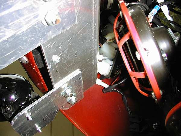
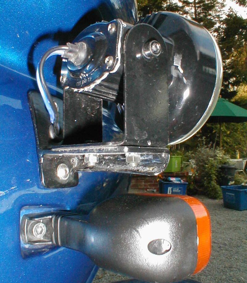
I made a
bracket out of aluminum plate. the plate is bolted to/through the plastic
headlight bracket (fender washers used for support), with a third mounting point
using the screw right in the middle of the fairing, just under the headlight.
this mounts my PIAAs about 6-8 inches apart, under the headlight. they are just
high enough that they wont hit the fender when bottoming out, and they are
narrow enough that they are protected from falls. My recommendation (assuming
the lights come with a switch), is to wire them "always on", then use a 3
position, 3-wire switch (hi-off-low) between your low current source and the
relay. one wire goes to the hi beam, the other to the parking light. this setup
will allow you to run your lights in any configuration, always on (low or high),
switched by highbeam, or off. I've got a stencil for the bracket I made, but the
shape where the lights attach is specifically for the PIAA 1200s. No welding was
involved. I had the metal shop where i bought the aluminum put a 45 degree bend
in it at about the middle (cost only a few dollars). Then I used a jigsaw
w/metal blade and a grinder to do the rest. can send you a picture, too. I
wouldn't want my lights attached to the fork tubes because they aren't
suspended. every road shock will be applied to the lights...bad on your eyes and
the bulbs. mark #403
Windshield Mounted
-
I
wouldn't put extra stress on those windshield screws in a million years. It must
work since they're selling them, but I still find it hard to believe that mount
is sturdy enough to hold extra lights. Thomas849 (Norway, '97ST).
Q. Will they overload my Alternator?
-
PIAA
1000's. The combined draw of 170 watts, will most likely exceed the excess
output of the F's alternator (275 watt - 170 = 105 watts). Several people
myself included run a pair of 55 watt (55 + 55 = 110 watts) PIAA's I can run
my lights alone without a problem but I do not try to run the lights and
heated grips at the same time too much draw. You could switch the bulbs in the
1000 to one of the PIAA bulbs which draws 55 watts but puts out 85 watts worth
of light. If I remember right the output of the Pegaso alternator is 175
watts, so one might think that there is at least 100 watts of excess capacity
in the classic F alternator. I have 55 watt PIAA lights mounted on mine, no
problem running the lights but I do not run my heated grips at the same time.
So far 3 years with no problems. Peter Jensen #233.
-
If you
have a classic, I recommend against buying anything that draws 110 watts. My
rectifier failed (just found out today), and they're saying it is due to
overloading the system. With only 280 watts, there's not much to spare. I'm
not sure I agree with them. I know I was cutting it close, but the one
variable I don't have the numbers for is how much the ignition draws. Just
thought I'd let you know, cause it's going to be a pricey fix. With
respect to the VR, I'm clueless. I don't own any heated clothing, but have
heated grips. I've run MANY times using a voltmeter (on my GPS, which reads
~.4V lower than actual, due to the diode, as it's been described to me).
Running the PIAAs and NOTHING else, voltage seems to be maintained at a
reasonable level, albeit slightly lower than without the lights on, perhaps a
half volt lower. turn on the grips, voltage drops to lower than ideal, even
dangerously low. I NEVER run the grips and lights together, and yet, my VR
failed. I don't know if it was due to the lights, but of course the dealer
wouldn't warranty it, stating the system had been over-taxed (and I have a
good dealer). it was actually BMWNA that denied the claim. You can't beat the
light output of the PIAAs, but when you add up the draw of the whole system,
you find that you are extremely close to maximum (for classic, 280w) without
including the ignition draw (nobody knows what it draws). and that does not
include turn signals, dash lights, fan, and any other overlooked draw. So far,
no one has posted that they use PIAAs all the time on their classic and have
had no issues with ANY electrical bits. so you are taking a chance. if you're
traveling internationally and want the light, go with PIAAs or Hellas. the
PIAAs are small, which is awesome...not sure about the Hellas, but the Hellas
tend to use h3 bulbs which are available almost anywhere. PIAAs tend to use
reflector/bulb units that you have to buy from PIAA (cha-ching...) do yourself
a favor and buy the VR in advance (about $150), and then HOPE that your wiring
harness to the VR doesn't look like mine. I replaced my wiring from the
alternator to the VR with heavy wire because my 3 yellow wires were toast. All
this applies to my '99. Mark #403.
-
Constant use of 2 - 55 watt driving lights, heated vest, and heated grips will
be more load than the Classic system will sustain - you might have better luck
with a GS but it's a lot of load. 2 - 35 watt lights and a heated vest is
probably the largest continuous load the Classic will sustain. Todd #389.
-
As I
remember, the MotoLights use a rather chintzy 12V insert, like you see in the
Hardware stores for an under-the-counter lights. The PIAA are 55W each so they
draw about 8 Amps total. I think your vest will draw about 70 Watts, but that
is intermittent--You don't run it full blast all the time. Either you turn it
on-off with a switch or the thermostat controller does it for you. If you draw
more than than the alternator can handle, then you pull some from the battery,
but as soon as the vest is off then the alternator feeds the battery again. My
assessment is that you would have no problem running the PIAAs, your head/tail
lights and your heated vest. Dick #420
-
Motolights draw 6 amps. NewMexEd.
-
Replace
your brake lights with LEDs. That'll save you some watts you can put toward
the headlights. Twinrider.
-
The
normal taillight doesn't consume all that much power -- just 15 or 25 watts.
And you should not be riding your brakes, so you need the higher-power (55W)
brake light only when you're braking. And for those short times, the battery
can supply that power. (In stop-and-go traffic you might not want to have your
high-beamers on anyway.) Timberwoof
Q. Why do I keep
Blowing Fuses after Installing them?
Q.
OK, the new "ally" lights work great, but I've blown two fuses in two days. But
they work great when the fuses are intact. It seems the fuse blows if I start
the engine with the high beams (and the Rally) lights turned on. I don't know
about the other years, but the '02 Dakar has the lights shut down while
cranking, and then they come back on after the engine fires up. This is when the
15A in-line fuse seems to blow. The relay I bought for the lights is not of the
same brand, but for a different brand driving light. Could the relay be rated
too high, and is drawing more power than the fuse can handle? If I use a 20A
fuse, am I likely to blow the halogen bulbs? The short-term fix is to turn off
the driving lights prior to cranking, but that requires me to remember to do so.
A1.
If I recall, your new lights are rated at 110 W. Add the 55-60 W that your
headlight uses and you're at 165 - 170 W. At steady state, the system runs at
around 12.6-12.8 V which is 13.5 A. However, as you start up and shut down, the
voltage varies. As the voltage goes down, the amps go up. You're not that far
away from blowing a 15 A fuse when your steady state is already at 13.5A. I'd
try a 20A fuse keeping in mind that the normal fuse for the headlight/turn
signals/horn/brake light is already at 15A. As far as blowing your lights, no
worries. The fuse just sits there fat, dumb and happy until is sees more than
20A when it blows. It'll pass whatever the load demands but no more than 20A.
A2.
Starting the bike with the light on puts a tremendous strain on the battery,
that's why there's a cut-out relay in the new bikes. Todd#389
A3.
How much current will a dead short pass?[1] It takes TIME to heat the metal
of a fuse to the point where it will melt. The higher the current, the less time
required. The fact that the fuse melts in a hurry when subjected to a gross over
current situation, rather than slowly as when subjected to a 5% over current
situation, is an indication that it will indeed pass the higher current. [1] the
supply voltage divided by the internal resistance of the voltage supply.
Then Check the
Electrical
Misc FAQs - Shorts - Blown Ignition Fuse Cure.
Q. Are they any
Good? Opinions
O - Alternatives
(generic)
-
Before
springing the big bucks for PIAA trot on down to Pep Boys. I kid you not. Look
at their Rally lights. They are the same lights for a tiny fraction of the
price. The packaging is even the same, silver cardboard wrapped around styro
with lights compartmented. I bought mine for $35 three years ago for my R1100GS.
They are identical to the PIAA 1400 series, 55w halogen bulb. At the time they
used the yellow dichroic reflector, the new ones have dichroic bulbs and blue
reflectors. What don't you get? The PIAA decal, the fancy switch and motorcycle
specific wiring. They come with miles of wire, for use on cars, and an ugly
rocker switch. I wired mine direct with no switch as I wanted them always on for
conspicuity. 3 years and 50,000 miles later, they're still shining, original
bulbs and all. I was in the store a few weeks ago, they still have a variety of
them for under $50, including the chrome units and the blue reflector models. I
swear they're all made by the same manufacturer and PIAA jacks the price 500% to
provide a cachet. Oh yeah, I think Wal-Mart has a small selection as well. Alan
#442 FL
-
I almost
bought a set of mini 55w lights, solid aluminum housings with brackets, a wiring
harness, switch and relay for $19.99 at Pep Boys. Wal-mart had similar items at
similar prices. But thanks for the warning Art, you are correct to advise
against installing extra lights (or anything really) without a relay. Mason #631
- 97ST in PA.
-
Flash has
sent to me some headlights so that I might be able to see where I'm going in the
dark (Harbor freight part number 37536-2VGA, www.harborfreight.com). I'm gonna
mount 'em somewhere on my '99 Classic.
Lights1,
Lights2,
Lights3.
-
In
attempt to better see those pesky deer at night, I just picked up a set of
Halogen "Rally" lights from NAPA for $59. These are 55watt lamps. I've read
through the FAQ, but didn't see any mention of this brand, so before I begin the
install, I thought I'd solicit some opinions. Also, has anyone put these kind of
lights on a Dakar? If so, where did you mount them? Scott, ID
-
Have mine
in my '00 classic since August past with good success and terrific illumination.
It's an EiKO (the quality lamp), part 6265, H4 12V, 100/80W, heavy duty. No idea
where or how my dealer got it but he said he's installed tons of them with no
complaints or melt downs. Art 884
-
Another
option is 55/100W bulbs...this assumes that you'll use the 55 at slow speed or
daytime running...and the 100W only at night at higher speeds (when you REALLY
need it). I haven't replaced my bulb in the F yet, but did in my old Airhead,
with great results. Marty #436-Chicago-97 F650F
-
It's very
possible to get great light without HID. My $40 Harbor Freight driving lights
don't generate enough light to warrant high speeds in the pitch black, but I can
do 75 with plenty of vis with my high beam and the driving lights on. I've
ridden with a Kaw ZZR12 and they have dual aircraft landing lights for driving
lights stock- HOLY KAW that's a lot of light. (admittedly they had to upgrade
the charging system to do that) It was like daylight at night except that even
on the divided superslab it was too bright for oncoming drivers. IMHO there's
enough juice in the charging system to handle nice, reasonably priced lights+
other farkles, you just have to be conscious of the power your
spending/depositing. You can't dog the generator if you're only pulling 3K on
the Tach. Also, it's possible to control lights individually based on your draw.
Once I get my genuine *Seacuke LED voltmeter* I'll be ready to throw some
serious lighting on- my HF fog lights were crap and they both had shorts in the
light itself- dead weight now. 2001 F650GS, Aurora, CO. chppdlvvr
-
I rode
around the woods (both asphalt and dirt) for several hours today with my aux
lights (110 watt), heated grips on high, and vest on 3 setting. No problem. It
still starts back up just fine. I don't have a voltmeter installed yet, but I
did notice the battery tender is staying in the charging cycle longer than usual
today. But at least it had plenty of juice left to start! Razz '03 black GS,
Colorado.
-
I have 2 BMW'S one is the adventurer the other a f650,Having spent wads of money
with BMW having the fogs lights supplied on my adventurer at a cost of 550 UK
pounds, I thought I would attempt to install some of my own on my 650, Here is
how I did it for a cost of less than 50 pounds, went to local car shop and
purchased a pair of small fog lights for 30 pounds, spent 5 pounds on a handle
bar switch, made a set of brackets to mount the lights on. The only down side to
the installation of the lights was I had to drill 2 holes on each side of my
fairing, but the result was good for a fraction of the BMW cost. Like the bike,
the lights are used on a regular basis and are very effective. If you wish to
see a photo of them please E mail me for a photo. kevig, F650, UK.
-
Next.
O - Hellas
Pictures of Light "Throw" from your chosen Hella Lights (Text in German).
See also
Install Report Below.
-
I have
HELLA FF50's and you can buy them
here for a very reasonable price. I
don't want to sound like a broken record or a salesman but I honestly endorse
HELLA driving lights. I've used them on all of my vehicles without a single
failure due to manufacturing. They are extremely resilient and I just can't find
anything about the PIAAs, aside from bragging rights, that is better than
comparable model Hellas. It is irritating to see someone drop 250 quid on a set
of lights that, IMHO, just aren't worth it. Here's a minor testimony to the
FF50's: I just came back from a little tour of the NW. 3800 miles later I find
myself on highway 90 between Spokane and Missoula in the middle of the night and
it's raining. Even though I was going slower than most other drivers wanted to
go, they would not pass me - but pull in next to me to let me light the canyon.
No, I wasn't being a prick and leaving my lights on when they did pass. I just
happened to be the brightest thing in the canyon. Yes, it was kind of a strange
experience, but if you spend twice as much on a "better" lamp then I think
you're strange :-). Jason#1027 UT. See the pics in the
GS Aftermarket Lights FAQ.
-
Hellas
aren't very fancy but they've been around for a long time. Parts can be found
worldwide in surprising places. Anytime you can replace a burnt lamp with a
standard part from a store down the block (or a Mongolian garage), rather than
have to order and wait for delivery, it's a big plus IMO. Todd #389
-
I ran
Hella's on my F before I sold it. They are great lights. Another advantage over
PIAA's is that replacement bulbs are a couple of bucks vs. the cost of a decent
dinner. Also, the bulbs are available at any automotive place. YMMV. Scott C.
#345
-
I just
put HELLA ff50's on my 02 Dakar. Easy install and very bright. Light bar came
from RCU. www.sierrabmw.com (Sparks, NV. has these in stock). $99 for the bar
$68 for the lights. Rollin rob.
-
I can
see! After getting tired of feeling blind at night on the freeway I just
upgraded my lighting as follows: Replaced 60/55 H4 with 100/80. Ok, I admit it,
I went with the "Xenon Blue". I like the color and the extra wattage makes a
huge improvement. Installed a pair of 55watt Hella OPTILUX fog lights using the
RCU Designs light bar. The FAQs were very helpful. The Hella lights were not as
pricey as the PIAAs. I used the RCU bar because I wanted isolate the lights as
much as possible from road vibration (the mount on frame instead of forks). I
wired these in just the low beams. I may change this later. The improvement is
incredible and so far nobody has flashed me about my bright lights. I will have
to watch to see if the new bulb gets too hot for the plug or reflector. I have
put a couple hours at night so far and it doesn't seem to be too much of a drain
on the charging system. The whole thing cost about $170. The light bar was the
most expensive at $100. Warren #1219, Pacifica, CA
-
I'm
currently working on installing Hella Micro DE fog lights (try a search on
Google). They're very small (maybe a bit long) and put out a lot of light. Can't
say much about them otherwise, as they're not on the bike. Paid $117 shipped. I
just got my Hella's installed on my bike (with some professional help with the
mount) and I'm very happy with it. Right now I'm using only one light, to see if
I can get away with it. 55W vs. 110W, plus I have heated grips. So far so good,
but I need to do some comparison runs with both lights to be sure what's good.
its_xls 2001 F650 GSA -- San Jose, CA.
-
Next.
O - Motolights
-
I have
Motolights on my 02 GS and I run with them on most of the time, day and night.
I've run them with my hand warmers on high with no problem. I haven't tried it
yet with my electric jacket. They are great for making you more visible and at
night you wonder how you could see before with only the headlight. My husband
has them on his bike, too, and I have ridden in front of him with his Motolights
and another guy on the same model of bike with PIAAs and there was a big
difference in visibility--the Motolights were much more noticeable. You can
adjust them so oncoming cars don't flash you at night, yet you can still see the
road well. I also put a PIAA super-white headlight bulb in with the same wattage
as stock, but brighter. They don't add a lot of extra light on low beam, but I
think it makes you more visible to cars because of the very white color. When
more cars have these bulbs, the advantage may go away. The bulbs definitely put
out more light on high beam, though. Bonnie.
-
I've got
Motolights too and can tell you that the bulbs are easy to replace by unscrewing
the metal/lens bevel with the "G" shaped tool included that comes with the kit.
I have done this a few times and tried different types (watts, beam spread,
brand) bulbs. The bulbs are simple 12-volt household type, about $8 each. I
ended up sticking with the stock GE 35 watt bulbs. I agree the switch is big and
ugly. I velcroed it to the top of the front fork shock riser, just under the
handlebar. I think the switch is important as these lights draw A LOT of juice
and can drain a weak battery in 5 minutes of sustained idling. They may be 75
watts but they draw current more like 500 watts. Joe #1065
-
I don't
like the moto lights because they are just 12V, under the counter kitchen lights
mounted in a very nice housing. No wonder they can give you "lifetime Warrantee
on the bulbs" If you want a real solid high intensity light, my recommendation
is the PIAA 1100X, now that is a real motoring light and reflector. Dick #420.
-
I have
MotoLights. If you ask me, they are not much more than FOGLIGHTS. If you want
driving lights, look elsewhere. I use Hella FF50's. In fact, I run both the
MotoLights (on the forks) and the Hellas (above the mirrors) on my RT. Can't do
that on the F, so you may want to consider something in between, like the PIAA
1100x's. Scott C. #345
-
I've run
PIAA add on lights before (Platinum Series on my1100GS) and they worked really
great, but look to spend lots for these(200$+). The Moto-lights are good, I hear
and draw about 35 watts each, I think. Simpler mounting to fork legs and less
draw on system than other brands, such as PIAA. Maybe not quite as much light as
PIAA add-ons, but still pretty good, I hear. Good luck. I know the desert
feeling in dark, with no moon, especially! Moon in desert at night makes quite a
difference. Go for a ride sometime with full moon (neat). Randy748
-
Buy a set
of MotoLights and your problems are over. They are very effective, easy to
install, and guaranteed for life! What more could you want ? I have them on my
Funduro and had them on my Roadster for 5 years. And, the people who own the
company are nice folks to do business with !! Steve#1059 in MA
-
Well, I
managed to install Motolights on my motorcycle this weekend . . . and I didn't
make anything explode! Installation was pretty simple, even for a hack like me,
and the instructions were easy to follow. A couple of things I've noticed about
them that I haven't seen mentioned, though:
1. The switch that comes with the kit is pretty ugly, and big too. For now, I
simply jumpered the switch wires together (so the lights are always on), but I
may add a different switch at some point (just so I can turn the lights off in
case of some sort of electrical emergency--otherwise, I intend to keep the
lights on all the time anyway).
2. The Motolight lifetime warranty includes free lifetime bulb replacement. I
was just about to email Motolight and find out why I didn't get a special tool
to unscrew the lens, but I decided to go out to the garage and have a closer
look first, Turns out, on mine, I can unscrew the lens by hand. So I stand
corrected--the bulbs _are_ easy to change.
3. I didn't want the stainless steel straps to scratch the fork tubes, so I got
straps that were 1/8" longer than I needed, and put some heat shrink tubing on
them. Looks great, and should protect the tubes a little. Josh #581
-
O - PIAAs
-
PIAA mounting kit. Just talked to the people at CBT
imports ---they say they will have a mounting kit for the PIAA 1100X driving
lights ready in about a month--the kit is for the F650 . It will mount the
lights on the stalk of the turn signal lights. They apparently will also have a
kit for the F650GS. To be advised when the mounting kit is available-they say to
send an e mail to them and they will advise when ready. Their e mail address is:
sales@cbtimports.com Bill # 391
-
I've broken more turn signals than anything else on my
F. If you go down, you
WILL break them. Do you really want to add $200 to that bill? Mark #403
-
I agree with Mark, I would much rather mount the PIAAs under the headlight where
they will be protected. Besides I now have flush mounted turn signals, so when I
go down I only scrape them a little rather than break off the Stalk. Dick #420
-
I put in
the PIAA 80/80, which IS much brighter, but that's because it is higher wattage.
Got 4 for $10 each in case they die early, but so far so good. $40 is just too
damn much money for a light bulb. Mason #631 - 97ST in PA
-
I paid
about 2X the price (as the HELLAs) for my PIAA kit including Relay and switch;
looks like it all comes in the Hella Kit. I have the PIAA 1100X and I really
like them. They make the night like Daylight. Dick #420
-
I have
the PIAA 1200's. if I had to buy again, I'd probably buy the 1100X's.
nonetheless, the 1200's are really too bright to use in traffic, even during the
day (although I sometimes use them when lane splitting, since I wont piss anyone
off for more than a second). I paid a discounted price for my lights (still over
$150, I think) as part of my bike purchase. replacement bulbs (actually a
bulb/reflector unit) are about $25 for the 1200's, $40 for the 1100X's. I
haven't needed a replacement in 3 years of vibrating on my f650. but the price
and availability of the replacements should be a consideration perhaps. I love
my PIAAs. they're bright, small, and robust. I fabbed a slick bracket that
mounts under the headlight (classic F), so the lights are out of harm's way in a
spill. I wouldn't want to sacrifice them at that price. My PIAA was shot after
about a year. I agree with your assessment, whiter, but not really brighter. I
replaced it with a $9 Sylvania (9003?=h4) that claims to be 20% brighter than
normal. seemed good and bright, not sure if it was REALLY any brighter. while it
was still good, I ordered a Phillips vision plus or something or other. you have
to order a pair, which was $28 including shipping. When the box arrived, they
sent me 3 bulbs. They were apparently having an unadvertised special, which was
a pleasant surprise. But now I have a lifetime supply of bulbs (my original
stock, the Sylvania, and two spare Phillips). I haven't ridden at night with the
Phillips yet, but I don't expect much difference from a regular h4. My PIAA
super white was only $32 from a BMW dealer. I have PIAA 1200s (110watts total).
they are awesome, as bright as I want, too bright for traffic and may have
caused voltage regulator failure. with respect to the VR (see above). The PIAAs
are small, which is awesome...not sure about the Hellas, but the Hellas tend to
use H3 bulbs which are available almost anywhere. PIAAs tend to use
reflector/bulb units that you have to buy from PIAA. Just hope the PIAAs don't
blow a bulb... gotta replace the whole bulb/reflector unit and the 1100x costs
somewhere around $45 EACH. So far, I haven't had to replace a bulb in my 1200s
($25 each). All this applies to my '99. Mark #403.
-
I mounted
my PIAA's 1100's with a Martin bracket on my GS. It wasn't that difficult at
all! The difference in riding is night and day :-) I found the PIAA's on sale
for 160 and paid 150 for the bracket (the part that hurt). I should say that the
brackets are made with so much precision that it looks like stock. In addition
Marin Fabrication claims that the lights will be safe even in a tip over. My
friend mounted the Motolights on his bike a few weeks earlier and the PIAA's are
hands down brighter. If you don't adjust them right you get hell of a lot of
people covering their mirrors when you pull up behind! Personally, I am not that
happy with the PIAA's (or any after market lights) when they are mounted up by
the headlights, since they are so bright that on coming traffic cannot see your
indicators at all. I am sure I could have rigged up something near the engine
guards but, when I tested that location found a lot of kick back from the
wheels...hence bit the bullet and bought the Martin bracket. Abe 963.
-
I'm not
so sure about the Martin Fabrication bars performing that well in the event of a
get off. I have PIAA's mounted on my Dakar with those same bars and it looks
awfully vulnerable. In fact, I would expect it to do some damage to the side
panels if the bike goes over. I have Motolights on my K12 and I feel that they
are every bit as good as the PIAA's in lighting up the road. They also
contribute more to "conspicuity" because of the way they're configured. Just my
$.02 worth. RogerN #827
-
I mounted
them on my Valkyrie. I bought some clamps that go on the engine protection bars
(notice I didn't call them crash bars!!) and then mounted the lights to the
bars. For the F650 I would build a bracket out of aluminum and mount the lights
under the headlight, or I might even consider mounting the PIAAs directly to the
plastic because they aren't very heavy. These lights are really great and turn
the darkness to almost daylight. Dick #420.
-
Web Bike World Articles. Scroll Down for Tech Articles on Lights, Headlight
Modulator.
-
On my RS, I'm running a pair of PIAA 1200s. I think
they're great. Expensive? Maybe. Especially when hooked up to the modified
euro-switch, and a full rewiring with heavy gauge wire and relays for the PIAAs
and both headlight circuits. Sometimes I run a higher wattage headlight bulb,
too. I've run 80/80s and 55/100s. I run around in the Rocky Mountains at night.
Deer and elk are everywhere. Lots of light is a good thing. Of course, a 700w
alternator doesn't hurt. I just took my F out for the first time in a couple of
weeks (I was doing a service on it and got distracted). What a pathetic stock
head light. Bryan #179 (NM)
-
I've got the 1200s on my '99 and they are incredibly
bright. besides being much brighter than the headlight (even an upgraded bulb),
they can be positioned where I want them to light the road. with an upgraded
bulb, you still stuck with the light pattern and position of the stock headlight
housing. the PIAAs are expensive (and $25 for a new bulb, if ever needed), but
so far, I have yet to see anything else even close. are they worth it? to me,
absolutely. and I would buy them again. but I'd probably check out the 1100x.
unless I'm mistaken, the MotoLights are also only 35 watts. Mark #403.
-
The Moto lights are much less output in comparison.
I used the 1100 Platinum series PIAA's on my big GS and the light was
incredible. I still stand by my single headlight switched bulb for my 650
answer. Not as much light, but Plenty strong over stock with three times the
light. Randy748/Calif.
-
I've been running PIAA Super brights for years with no problems. The PIAA on my
KLR has three years and 29,000 miles on it with no failures. The PIAA in my 01
Dakar has two years and 12,000 miles on , which includes 5000+ miles from the
Alcan 5000 which was breaking parts of some bikes. I can't complain, but I
understand your frustration. I personally swear by the PIAA stuff. Let me say
first that I have no brand loyalties in anything, if it doesn't work, I'll say
so. They sponsored me in the Alcan 5000 with their new 2.75" Xtreme White
running lights and they are nothing short of awesome! The whole trip, including
a rough 300 mile section of dirt and gravel (including 1' washouts) never
affected these lights, not to mention that they're brightness and spread were
equal to much larger aux. lights. Very compact and when mounted below and
forward of my turn signals, survived three bike-down episodes. Skip
-
I've tried PIAAs and don't recommend them. I bought
two, one didn't fit the headlight properly and the other seemed to have improper
focal properties and needed a lot of adjustment to get the beam on the road
properly. High priced junk... '98 KLR 650, Fort Collins, CO. Harl #380
O - Touratech Fog & HID Lights
-
Seemed nobody in the list has the Touratech fog lights in their bike so I took
the plunge and ordered a pair of lights for my GS. It arrived today and I had it
installed by a bike mechanic. It cost me $280 plus shipping to the Philippines
and I'd say, I'm very satisfied with it. I think its quite expensive for fog
lights but the build finish seems to be of high quality. By the way, the bulbs
are by Hella . It came with relays and 2 switches but I only used one. It seemed
quite simple to install and there's no need to do modifications on the bike to
put the lights on. My friend here just got the Touratech HID light for his bike
and is yet to be installed. I really liked this initially but the cost ($389 for
just one side) kinda turned me off. jagged F650CS, F650GS Phillipines
-
My friend just had his Touratech HID light installed last week and what I can
say is that its ALOT brighter than my fog lights. Regarding
installation...basically, it seems that Touratech used standard Hella light
assembly in their lights w/ their custom mounts hence the high price tag ($389
for 1 HID light w/ mount). We didn't modify the bike's electrics in any way and
just followed the supplied instructions w/c wasn't very clear so we had to
figure out some part of the installation process. The Touratech HID fog light
turned on when you switch to high beam and I'm not sure if you can make a
separate switch for it. On the other hand, my non-HID fog lights came w/ a
switch to turn it on. The nice thing w/ the HID is that it makes the road much
brighter but its a bit blinding to incoming traffic. With the normal fog lights,
I get a wider vision at night compared w/ just the stock lights. jagged F650CS,
F650GS Phillipines
-
We have the Touratech HID driving light on one of our F650 Classics. The
results, IT WORKS. I will do a write up when I get home from Mexico. A couple of
notes, watch your battery water level, and the mount needs to be modified to fit
the Classic. These lights are available from Mr. d's. Best Regards, Don#301 Mr
Ed's Moto Accessories.
-
-
The one thing about the more expensive Xenon (HID) light from Touratech is that
it is only supposed draw 35w instead of the normal 55w for this size light. If
you are really are at the limit on watts then it might the way to go. Brad, N.
CA., 2001 F650GS - Inmate #1002
-
Next.
Light Installations for PIAA Lights
 PIAA Installation #1
04/11/99
Mark #403
I wrote the following out
quickly and in piecemeal fashion. It's not a perfect solution, but it works for
me and I actually love the placement. Also easy to adjust angles, etc. The PIAA
switch is velcro'd to the base of my left mirror where I can reach it with my
thumb. If you try something like this, just don't mount them lower than I did or
the wheel could hit under full compression of the shocks.
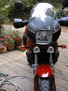 Instead
of using a single piece of aluminium, I used 3 pieces that I bolted together.
Eventually I will redo this with a single piece, file the two extensions that
mount the lights so that they match exactly the shape of the light bases with no
overlap (or actually underlap),
and paint the whole thing black. So I wont describe exactly what I did, rather
I'll describe what I intend to do sometime in the future. You can see the
difference between my description and the pictures for yourselves. The one
benefit to having done it this way is that the two pieces mounted to the bracket
allow the lights to be a little wider apart because of their shape. It's a
little hokey, I know, but you can't see the bracket at all unless you get under
the bike.
Instead
of using a single piece of aluminium, I used 3 pieces that I bolted together.
Eventually I will redo this with a single piece, file the two extensions that
mount the lights so that they match exactly the shape of the light bases with no
overlap (or actually underlap),
and paint the whole thing black. So I wont describe exactly what I did, rather
I'll describe what I intend to do sometime in the future. You can see the
difference between my description and the pictures for yourselves. The one
benefit to having done it this way is that the two pieces mounted to the bracket
allow the lights to be a little wider apart because of their shape. It's a
little hokey, I know, but you can't see the bracket at all unless you get under
the bike.
 I got the aluminium pieces from
a local sheet metal shop that I found in the yellow pages. Total cost was less
than $20, including the bending and cutting. The shaping and further cutting of
the pieces I did with a jig saw and files. The aluminium is really easy to work
with. However, it took two attempts with slightly different approaches, each
time really an experiment, both times frustrating. It will be smoother next
time.
I got the aluminium pieces from
a local sheet metal shop that I found in the yellow pages. Total cost was less
than $20, including the bending and cutting. The shaping and further cutting of
the pieces I did with a jig saw and files. The aluminium is really easy to work
with. However, it took two attempts with slightly different approaches, each
time really an experiment, both times frustrating. It will be smoother next
time.
What you need:
- 1/8 aluminium sheet, 8 wide X
approx 8 long with approx 60 deg bend across width, two inches down from top.
- Some hardware of your choice (nyloc nuts, bolts, washers)
- Wrenches to match hardware
- Propane torch or other high heat source
- Files
- Hacksaw or jig saw with metal blade
- Vice (when cutting/filing)
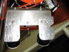 The 2 angle is attached to the
plastic frame that holds the headlamp (that's the only part about the install I
don't like). I drilled two holes into the plate matching the hardware size in a
location that I knew would contact the plastic frame. I heated an extra bolt red
hot, held up the plate where I wanted it, and melted two holes into the plastic,
through the holes in the plate. If you have a flat angle drill, that would be
better than melting, but I don't. I had to file notches into the plate where it
exited from under the fairing so there would be no metal-to-fairing contact, yet
allow the plate to exit as high as possible. Now, mount the lights where you
want them and draw around the bases with a pencil. With a saw, take off as much
bulk as you can and file the rest to the shape you want.
The 2 angle is attached to the
plastic frame that holds the headlamp (that's the only part about the install I
don't like). I drilled two holes into the plate matching the hardware size in a
location that I knew would contact the plastic frame. I heated an extra bolt red
hot, held up the plate where I wanted it, and melted two holes into the plastic,
through the holes in the plate. If you have a flat angle drill, that would be
better than melting, but I don't. I had to file notches into the plate where it
exited from under the fairing so there would be no metal-to-fairing contact, yet
allow the plate to exit as high as possible. Now, mount the lights where you
want them and draw around the bases with a pencil. With a saw, take off as much
bulk as you can and file the rest to the shape you want.
 Obviously, I filed each of the
two small pieces individually, then bolted them onto the bracket. The last thing
I did was drive a screw through the centre into the plastic tab attached to the
fairing for added support. Considering the bracket is mounted to the plastic
frame, they are actually very solid and don't vibrate like I thought they might.
Obviously, I filed each of the
two small pieces individually, then bolted them onto the bracket. The last thing
I did was drive a screw through the centre into the plastic tab attached to the
fairing for added support. Considering the bracket is mounted to the plastic
frame, they are actually very solid and don't vibrate like I thought they might.
Good luck with
whatever you do. By the way, the $160 price you found on the internet is the
same price I used to negotiate with my dealer. If shipping's not too bad, it's a
good price. They're $195 everywhere else I've seen
them.
Installation is pretty basic:
- My PIAAs came with a relay and a little
crimp/splice connector that was supposed to be wired to the highbeam (+).
instead of going to the highbeam, I wired the relay to a 2-position, 3-wire
switch (waterproof, from an auto parts store, mounted through the dash).
- The middle wire on the switch (out) was the
wire to the relay, which required a (+) feed. the upper wire on the switch
(in) was a wire tapped into the highbeam (+). the lower wire on the switch
(in) was a wire tapped into the parking light (+).
- So when I have the switch in the up position,
the PIAAs will only work if the high beam is on (i.e. controllable by the left
thumb switch). when the switch is in the lower position, the PIAAs will work
any time. and of course, the master control is the other switch that came with
the PIAAs. if it isn't on, the lights wont be on regardless what position the
dash switch is in.
PIAA Installation #2
By Flash #412
Homemade Light Bar Installation:
The Wolverine gave me a set of PIAAs that she pulled off her International Scout a decade or more ago. I went down to Home Depot and bought a couple of galvanized brackets used for attaching a wooden 4x4 to something or other for about $2.50 apiece. I cut some of the tabs off the brackets and drilled some holes in them. Using a grinder, I radiused the ends to match the radii of the PIAA brackets. I broke the other corners and edges with a file and then painted them with black semi-gloss engine enamel followed (after appropriate drying time) by treatment with a heat gun to harden the paint.
I drilled holes and mounted the brackets to the plastic engine side covers below the gas tank with a couple of screws each. I soldered some ring terminals on the ends of a pair of pieces of wire an inch or so long to be used as safety restraints in the event that the brackets break from fatigue while I am riding. Hopefully I would notice the light dangling and rescue it if the brackets turn out not to be up to the job.
The brackets follow a line on the plastic that tilts them forward. This is a Good Thing since it means that the lights are tilted somewhat up when the bike is unladen. With a load, the back of the bike drops some which means the lights need to be tilted down so they don't shine up in the trees. If the brackets were level with the ground, I might not be able to get enough down-tilt to keep them where they need to be.
The angle brackets are splayed slightly OUT as attached to the bike. But the PIAA brackets have enlongated holes that allow enough left-right adjustment to get the lights pointed in the right direction.
I ran a healthy wire (via a fuse) from the battery to a relay TyWrapped to the frame that holds the fairing. The relay is activated by a three-position (center off) SPDT switch AND via a diode from my horn relay. The diode connection means that whenever I beep the horn, the lights will be illuminated as long as the horns are blaring (if they aren't already on). (The diode keeps the fact that the lights are on from beeping the horn.) One leg of the switch is connected to the parking light circuit. (I have a Euro lightswitch and can run only the parking lights if I want.) When the switch is in that position, whenever the ignition is on and any lights at all are on, the auxillary lights STAY on. The other switch position is wired to the high beam signal. This means that whenever the highbeams are on, whether flashed or on steady, the auxillary lights will illuminate, but go off when on low beam (or parking light only, or not lights at all).
The light brackets were attached to the angle brackets and the angle brackets to the bike side covers with 4mm screws and hardware. In the photos, the nuts are regular nuts with washers and locknuts. But I later replaced the standard hex nuts with NyLock nuts, retaining the other hardware.
Each light is grounded at its nearby radiator mount. Each of the hot wires runs up around the steering head and into the area under the dash inside some clear plastic Tygon tubing to avoid and chafing and shorting. Where the hot and ground wires join together to go to each light, the pair runs inside heat shrink tubing. The wires simply come out from under the fairing and go to the lights. Molex connectors were used near the lights to simplify removing the lowers when necessary for maintenance or repairs.
The PIAAs each have a 55W bulb in them. Turning them on casts a blue-yellow light. Riding out in the boondocks at night, the difference between just the stock headlight and with the auxillary lights is almost like night and day. I think I am spoiled. I haven't taken any long rides at night with my GSP-voltmeter yet. But riding ten miles with the lights on seems to have no deleterious effect on the state of the battery charge. It is summer, so I haven't tried them with my heated grips and/or electric vest. I figure that if I notice the voltage dropping while running heated accessories, I can either turn them off for a few miles or else just unplug one of them. If I were to drop the bike and destroy the PIAAs, I'd probably replace them with some different (MUCH less expensive) lights.
Here are a few photos showing how they ended up. (Sorry about the crappy focus on the second shot.)


F650ST Driving
Light
Teddco #1192 GA 97ST
01-Oct-02
Anyone looking auxiliary lighting for an F650 may want to consider he setup
shown in the photos.


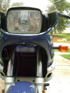
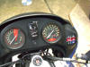
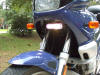

- I bought a set of remote controlled, 55-watt
automobile driving lights at Walmart, Cyber White Remote Series NV-526W by
Navigator, $39.00. Cut one driving light off the wiring harness, terminate and
seal bare wire ends in the harness. (I put the amputated light on my wife's
Honda Rebel.).
- Widen the slots in one mounting bracket to the
size of the bolts that hold the horn bracket casting on the underside of the
lower triple clamp.
- Mount light bracket under horn bracket bolts.
- Mount light that is still attached to wiring
harness.
- Fashion a bracket out of pipe hanger and
mounted the receiver (visible in photos) inside the fairing, fastened by the
nut that holds the right front turn signal.
- Remove gas tank, route harness, secure with
cable ties.
- I ran hot and ground directly to battery since
harness has in-line fuse.
- Mount remote holder with double sided tape to
dash.
- I added some thin elastic cord on the remote
that slips under the holder to keep it in place. Still plenty of room between
light and fender.
- Nice wide, spread out beam that turns with
forks.
Optilux Driving Light Install
by Will in CA

I have
installed the Optilux lights by Hella available at JC Whitney for 49.99 plus
shipping (part # 07UB3236P this is the round model with clear lens). In the
event a
bulb burns
out they use 55-watt H3 halogen bulbs available at most auto parts stores. I
did use the relay that came with them but the wiring harness and switch were
really cheap so I got my own 3 way waterproof switch, fuse holder and the stuff
to make a wiring harness.
|
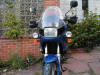
FRONT VIEW OF MOTORCYCLE |
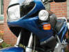
LEFT SIDE VIEW OF
MOTORCYCLE |
I made
brackets that mount the lights to the fairing just above the turn signal lights.
|
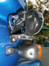
CLOSE UP OF LIGHT BRACKET |
ANOTHER CLOSE UP OF THE
BRACKET |
I used the
same rubber nut thingy’s and screws used to hold the “classic” windscreen (BMW
part # 46 63 2 345 091) in place hoping
that if I take a fall the rubber will pull through the plastic instead of
breaking it. I wasn’t sure if they would hold up to the task but they do. They
have been tested now with thousands of miles including rough dirt roads at high
speeds with plenty of vibration and nothing has come loose.
CLOSE UP OF THE WELLNUTS

CLOSE
UP OF THE WELLNUTS |
The switch
and indicator light are mounted using a bracket made from stainless steel sheet
metal held in place by the two Allen head bolts (replaced with longer bolts)
holding the left mirror to the handlebars. If I
were to make another I would put the large hole that mounts the switch another ¼
inch or so further away from the handle bar (towards the rider) allowing a
little more room to operate the high beam low beam switch. Because prototypes
out of aluminum are easier to make and the metal can be purchased at many
hardware stores this is recommended. The final installation could also be done
with aluminum but I like the shine of stainless steel. Directly behind the
stainless bracket are stacked washers as spacers on the new longer bolts
allowing the bracket to sit with no pressure on the rounded part of the mirror
handle bar clamp. More washers are required for the bottom bolt because of the
design of the mirror handle bar clamp.
With a
full-face helmet the indicator light is just out of view.
It should be considered that this little light can
be annoying at night if it’s two bright or in the wrong place.
|
CLOSE UP OF THE LIGHT
SWITCH BRACKET FROM THE LEFT |
CLOSE UP OF THE LIGHT
SWITCH STRAIGHT ON |
The three way switch is wired so the up position is running
the auxiliary light with the high beams the middle position has the auxiliary
lights off and the down position runs the auxiliary lights with the running
lights (on all the time; thanks Rodskogi).
The new relay is mounted under the dash just behind the
tachometer. Using wire ties it’s hung from the fairing-mounting bracket on the
left side positioned so the terminals point down. Marking the terminals using
tape on the sides makes it much easier to read the terminal numbers with the
relay mounted. Other wise it’s very difficult if not imposable to read the
numbers with the relay mounted.
-
Run
a new hot wire from the terminal 30 on the relay to the battery (remove the
fuel tank to do this) with a fuse close to the battery.
-
Two hot wires go from terminal 87 of the relay
to the each of the new lights.
-
The other wire on the new lights goes to ground,
any good ground to the frame will do.
-
Connect one wire from the relay terminal 85 to
ground (a wire can be run from the battery ground although it’s not necessary
as long as it’s a good ground to the frame).
-
One wire goes from terminal 86 on the relay to
the middle position of the new switch.
-
From the EXISTING high-beam wire near the
connection on the back of the head light bulb (you may be able to find another
spot to tap into this) run a wire to the new switch high position.
-
The low position on the new switch connects to
the EXISTING parking lamp wire just behind the head light (you can tap into
other spots for this one).
I also included an indicator light (small) letting me know
when the auxiliary lights are on.
All in all
I have many hours invested in the whole get-up but am quite pleased. Wow! What
a difference. When I turn them off I wonder if my regular headlight is still
on. On the twisty roads these are really great. My friends tell me that in the
day from afar I look like a car.
Taillights
Hyperlights
and Light Buddies for F650
22/03/00
Scott #345
Over the past few weeks I have
made two lighting additions to my bike that I now consider necessities for safe
riding -- both at night and during the day.
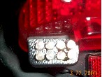 First,
I installed M&G Accessories' Hyper-Lites. Hyper-Lites consist of two 1-1/4 x
3/4molded plastic units containing two rows of four LED's. When installed, the
units act as additional brake lights that are off during normal riding, blink
for 5 seconds when the brakes are first applied, and stay on bright until the
brakes are released. They also have a set which will blink forever when the
brakes are applied, but I chose to spend the extra money to get the ones that
are not quite so annoying to others.
First,
I installed M&G Accessories' Hyper-Lites. Hyper-Lites consist of two 1-1/4 x
3/4molded plastic units containing two rows of four LED's. When installed, the
units act as additional brake lights that are off during normal riding, blink
for 5 seconds when the brakes are first applied, and stay on bright until the
brakes are released. They also have a set which will blink forever when the
brakes are applied, but I chose to spend the extra money to get the ones that
are not quite so annoying to others.
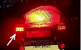 M&G suggests that Hyper-Lites
be installed under the plastic taillight lens. However, I found that they could
be mounted within the lens. Despite the cleaner look this provides, such an
installation limits the light's effectiveness as the brake lens tends to scatter
some of the light. When mounted below the lens as suggested, they are extremely
bright, and impossible to miss.
M&G suggests that Hyper-Lites
be installed under the plastic taillight lens. However, I found that they could
be mounted within the lens. Despite the cleaner look this provides, such an
installation limits the light's effectiveness as the brake lens tends to scatter
some of the light. When mounted below the lens as suggested, they are extremely
bright, and impossible to miss.
Installation
was surprisingly easy as M&G provides all the wiring and piggyback connectors
required. They also provide very detailed instructions that clearly explain by
coordinated colors which wires connect where.
 With
the piggybacks, you merely pull off the existing wire, connect the piggyback,
and then re-connect the existing wire to the back of the piggyback - forming a
dual connection. With the exception of a short length of visible wire, all the
connections fit neatly behind the taillight assembly
and out of site. Although I don't recommend it, I should note here that the
installation could be completely stock looking if the Hyper-Lights are mounted
inside the taillight lens.
With
the piggybacks, you merely pull off the existing wire, connect the piggyback,
and then re-connect the existing wire to the back of the piggyback - forming a
dual connection. With the exception of a short length of visible wire, all the
connections fit neatly behind the taillight assembly
and out of site. Although I don't recommend it, I should note here that the
installation could be completely stock looking if the Hyper-Lights are mounted
inside the taillight lens.
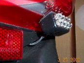 Despite testing various
mounting locations, and my near mechanical incompetence, installation about 45
minutes. If you install the lights in the location recommended right off the
bat, installation should take no more than 30 minutes. Even better, the units
work better than advertised and the total cost was $49.50.
Despite testing various
mounting locations, and my near mechanical incompetence, installation about 45
minutes. If you install the lights in the location recommended right off the
bat, installation should take no more than 30 minutes. Even better, the units
work better than advertised and the total cost was $49.50.
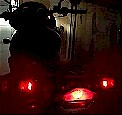 Content
with my ability to be seen during braking, I decided to add some running lights
to increase visibility during normal riding. This time, my lights of choice were
Scooterville's LIGHT-BUDDYs. Similar to the Hyper-Lights, LIGHT-BUDDYs consist
of molded plastic units with integral LEDs. However, each LIGHT-BUDDYs unit has
only one row of four LEDs, instead of two rows. The special shape and reduced
size allows the units to be installed completely within the turn signal pods.
Once installed, the lights only have one function. Namely, to remain on at all
times as running lights. Although they are on
at all times, there is no interference with turn signal operation as the LIGHT-BUDDYs
are overpowered by the blinking yellow turn indicators when you turn.
Content
with my ability to be seen during braking, I decided to add some running lights
to increase visibility during normal riding. This time, my lights of choice were
Scooterville's LIGHT-BUDDYs. Similar to the Hyper-Lights, LIGHT-BUDDYs consist
of molded plastic units with integral LEDs. However, each LIGHT-BUDDYs unit has
only one row of four LEDs, instead of two rows. The special shape and reduced
size allows the units to be installed completely within the turn signal pods.
Once installed, the lights only have one function. Namely, to remain on at all
times as running lights. Although they are on
at all times, there is no interference with turn signal operation as the LIGHT-BUDDYs
are overpowered by the blinking yellow turn indicators when you turn.
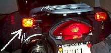 Installation of the LIGHT-BUDDYs
was a bit more involved than the Hyper-Lights because you have to drill two
holes, install final piggyback connectors manually, and snake wires around
quite a bit. That said, I don't suggest that this was difficult at all. Anyone
who can install the Hyper-Lights and use a drill should easily be able to
install the LIGHT-BUDDYs.
Installation of the LIGHT-BUDDYs
was a bit more involved than the Hyper-Lights because you have to drill two
holes, install final piggyback connectors manually, and snake wires around
quite a bit. That said, I don't suggest that this was difficult at all. Anyone
who can install the Hyper-Lights and use a drill should easily be able to
install the LIGHT-BUDDYs.
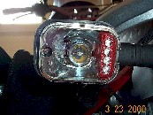 Basically,
the lights stick to the silver reflective surface inside of each turn signal
pod. A 3/16 diameter hole must be drilled in the reflective surface so that the
wires can pass to the rear of the pod. Then, the ground wire connects to the
existing ground in the turn signal pod using a factory installed piggyback
connection. The hot wire (with bare end) must then be snaked through the turn
signal stalk to the rear of the brake light assembly. Once snaked, you have to
crimp a piggyback connector on so it can be connected to the hot of the brake
light. Do that for each lens and you are done. All told, installation of the
LIGHT-BUDDYs should take less than one hour. Total cost for both LIGHT-BUDDYs
came to a reasonable $36.00.
Basically,
the lights stick to the silver reflective surface inside of each turn signal
pod. A 3/16 diameter hole must be drilled in the reflective surface so that the
wires can pass to the rear of the pod. Then, the ground wire connects to the
existing ground in the turn signal pod using a factory installed piggyback
connection. The hot wire (with bare end) must then be snaked through the turn
signal stalk to the rear of the brake light assembly. Once snaked, you have to
crimp a piggyback connector on so it can be connected to the hot of the brake
light. Do that for each lens and you are done. All told, installation of the
LIGHT-BUDDYs should take less than one hour. Total cost for both LIGHT-BUDDYs
came to a reasonable $36.00.
Each product can be purchased
through their respective manufacturer. I obtained them from my dealer, Cross
Country BMW, who keeps them in stock. Addresses and phone numbers for each are
listed below. Hope this tip helps you to be seen. Good luck with the
installations.
Scooterville, Inc.
6701 W. Lake Anne Dr.
Raleigh, NC 27612
(919) 782-7539
Opinions on Aftermarket
Tail-Lights:
ATL: Aerostich
-
Aerostich has an
LED replacement for the stop/taillight bulb that most bikes & cars use. Being
an LED it shouldn't be affected by vibrations as much, and also draws much
less current. The price is about US$17. You can probably find them from other
sources as well. For some the hefty
price is worth it, as there's nothing worse than having a bulb fail at night
on not knowing about it. Don't Screw the
two Plastic Cover screws too tight, just snug or you will break the Plastic!
HsN.
ATL: Backoff
ATL: Generic
ATL: Hyperlites
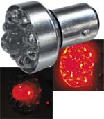
-
I also use the Hyperlites. Mounted them lower on the bike than suggested to
widen the night profile. Took almost no time to install. Wife says mandatory
that I use them on any bike I have because of the visibility improvement. David
#651
-
Bought mine from Hyperlites directly. If you use PayPal it
is quick and easy. The install was pretty simple and they include decent
instructions. I had to bend the new saddle connector a bit to allow the assembly
to go back together without pinching the wire. The whole job took about 30
minutes. Having a set of real Torx drivers and a 10mm socket/wrench will make
it easier. They are bright as heck. I imagine some people behind you at stop
lights will find the blinking feature annoying if you need to hold the brake. It
can be altered to blink for a few seconds and then go solid. Ditto on the Hyper
Lites. Make sure the surfaces are VERY clean before applying the double stick
tape. I had one drop off but they sent new tape at my request.
http://www.hyperlites.com/unikits.html BradG#1002.
-
Ordered Hyperlights late last week and they arrived and
were installed last night. Simple two wire hook up and I left the green wire
intact so that they flash continuously when the brake is applied versus the
5-sec. flash. I commute 2-days per week here in PHX and wanted some extra
visibility during darkness to/from work. This was on a 2001 F650GS Dakar. The
instructions say to remove the 10mm nuts that fasten the entire fixture to the
plastic mounting. I couldn't see how to get to the 10mm nuts so I loosened the
top two Torx bolts and the bottom two just enough to slide the entire plastic
piece off of the motorcycle. Then, I could easily access the 10 mm nuts to
separate the fixture from the plastic mount. Once you do that, you're at the
back of the power connectors. Take off the stop wire and plug in the blinker
wire. The stop wire piggybacks onto the blinker wire. The other connection is
the ground so you remove it, plug in the blinker ground and then piggyback on
the original. Fasten everything down with double-sided sticky take, button it
all back up, presto-chango, you're done. The only cutting to consider is a green
wire that you might cut if you only wanted the blinkers to work for 5-seconds
regardless of if you're holding the brakes or just touch them. There's probably
pros and cons to each so I'll leave it intact for now. If you were to cut it,
all you have to do is tape off the ends. Very happy with the result.
http://www.hyperlites.com/F650.html Gerry, #951
-
I'd also recommend the Hyperlites. I really liked them on
my F650, and I'm probably going to put a set on my Gran Canyon within the next
week or two. Get the three-way ones, and they make great running lights (low
intensity), as well as brake lights. The instructions for the F650 are also
really easy to follow (hey, if *I* can install them without any problems,
*anyone* can!). Josh #581
-
I love my Hyper Lights. I wanted to get the lights up
higher, so I lengthened the leads, and attached them to the bottom of my Givi
top case, as far out to the sides as possible. They are much more visible there
than in the standard location under the tail light. I also found that they are
very directional - brightness changes a lot if not shining right in your eyes.
Take pains to aim them. Scott LS
-
I used a halogen
bulb as a tail / stop light for a while. But I found that the added current
resulted in pitting and burning of the bulb contacts, to the point where it just
stopped working. I went back to the stock tail light, and added LEDs
(Hyperlights) for added rear end visibility (love 'em). Bob#550 (Olympia WA).
-
I have a 2001
F650GS fitted with both the Hyperlights (5 second flashing) and Signal Dynamics
classic license plate with the single top row of LEDs which mimic the tail
light. When I ride in the city (Seattle) probably 80% of the bike messengers who
see them comment on how visible the Hyperlights are. None of them have commented
on the Signal Dynamics LEDs as yet. The Signal Dynamics LEDs are not as
obviously added on as the Hyperlights and this may be why they do not get
commented on. Still the positive reactions to the Hyperlights from a group of
people whose lives depend upon being seen in traffic makes me happy I’ve added
them to my motorcycle (makes my wife happy too). LeeG.
-
Super easy to
install, and they are really bright. A friend who followed me in a car once said
that they were very bright and noticeable. I have mine set in the
blink-for-5-seconds mode. Robert in TX #959 Robert in Texas #959 -- Black '97
Classic
-
Installed
Hyperlights on my 02 GS last night. Used kit which has running lights and stop
flashers. Install was simple, but did have to make a few modifications. First
problem, flasher box would not fit through tail light rear wiring hole. Simple
fix, enlarged hole. Second problem. Piggy back connectors pointed wiring
connector straight back against lens mount. You are unable to mount lens,
without crushing connectors. Simple fix, bent piggy back connector at 90 degree
angle. Hyperlights is a great product. y2kcorvette.
-
Installed duel
purpose hyperlights on my 02. Took under an hour for install, instructions come
with kit. Duel purpose lights stay on under normal riding and flash when you
brake. You can set stop flash 5 seconds or non stop flashing. Hope this helps.
'02 F650GS, '02 K1200RS, N California. y2kcorvette
-
Installed them on
my 03 CSA and I love them! Anything to help be noticed in the crowd! Also had a
modulator installed in my front high beam. It's great - flashes the bright light
on and off. Automatically shuts off at dusk. '03 F650CSA, Kingwood, TX. d2
-
I did find a very
curious thing about the brake light on my '03 CS with ABS: There is about 6
volts across the brake light bulb even when the brake light is not on. In other
words, if you remove the bulb, you will find 12 volts across the tail socket
when the brake light is activated, but there will still be 6 volts across it
even when the brake is not activated. I suspect the 6 volts is the sensor
current that others have mentioned as the means for sensing when the bulb
filament is burned out. In my case I replaced the bulb with a multi-LED bulb
that functions as both tail light and pulsing brake light. What I found was that
with the LED bulb the brake light was on all the time. Apparently the 6 volts on
the brake light circuit was enough to activate the brake light on the LED bulb,
even when the brake was not pressed. My solution was to wire a small 3300 ohm
resistor from the hot side of the brake light circuit to ground, thereby
simulating the presence of the brake light filament. That worked, and the LED
light now works just fine. Will in Arizona, USA, '03 F650CS. DesertRider
-
Next.
ATL: Kisan Taillight Flasher/TailBlazer
-
I installed the Kisan
taillight flasher and then decided that the stock tail-light just doesn't
produce enough light. I ordered some Light Buddies, but then returned them, as I
found what I thought was a superior solution. Unknown
-
The tailblazer is a
modulator which causes the tail light to blink for 5 seconds when the brakes are
put on. I have one of those already. For more info see
Kisantech.com. The
splice-in refers to additional wires which are attached for another function,
such as 4-way emergency flashers. Chris #856 '99F Fremont, CA
-
SignalMinder I have
them and I think they are great, I don't know which brand I have as I bought the
bike with them. MasterITRIT #F650-1231 -- '98 F650 Classic -- '80 Yamaha XT250
-- Rochester, NY.
-
I've had flashing
brake lights on a couple of bikes and I think they have value as an extra
warning to other drivers. I currently have a Run-n-lights model that is a
separate light bar that goes beneath the license plate. On a previous bike, I
had Life-Brite lights, which are small, separate led lights that attach to the
side of the plates. Both of them have worked without problems. One important
thing to remember when installing them is that they must be lined up exactly
square--that is, facing straight backwards--not tilted up, down, or towards the
center of the bike. My husband put his on facing inwards just a little bit and
the LEDs did not show up very well at all from behind. When lined up right, they
show up very well. We had the Tailblazer flashing bulb, but they were not
durable and the electronic flashing control burned out on both of ours very
quickly. I've never used the type that fit inside of your turn signals, so can't
help you there. But I think that having an extra, external set of lights like
the ones above are better to get more attention. Bonnie #1158 -- Northern
Illinois -- '02 F650GLA
-
I have the
Tailblazer, and I love it. I get a little self conscious about ppl thinking my
flashy's are annoying. But otw, it's there and it serves me very well. Plus, the
bulb and unit are separate, so Kisantech.com sends a free extra bulb if the
light ever goes out....which it hasn't. I really liked how low-tech the thing
was. just pop-in and go. FULL ENDORSEMENT. Docc, Austin, TX '02 GSA Black Inmate
F6501249'
ATL: LifeBright
I've
had flashing brake lights on a couple of bikes and I think they have value as
an extra warning to other drivers. I currently have a Run-n-lights model that
is a separate light bar that goes beneath the license plate. On a previous
bike, I had Life-Brite lights, which are small, separate led lights that
attach to the side of the plates. Both of them have worked without problems.
One important thing to remember when installing them is that they must be
lined up exactly square--that is, facing straight backwards--not tilted up,
down, or towards the center of the bike. My husband put his on facing inwards
just a little bit and the LEDs did not show up very well at all from behind.
When lined up right, they show up very well. We had the Tailblazer flashing
bulb, but they were not durable and the electronic flashing control burned out
on both of ours very quickly. I've never used the type that fit inside of your
turn signals, so can't help you there. But I think that having an extra,
external set of lights like the ones above are better to get more attention.
Bonnie #1158 -- Northern Illinois -- '02 F650GLA
Life-Brite Flashing LED Brake Lights: Do they mess up ABS? I called
Life Brite and the guy said there were
no problems that he knew of. My dad also emailed the guy who we bought these
from, here is the email we received from him:
--------------------------------------
RE: Re: Life Brite LB-100A
Your dealer is a moron...er.. I mean... misinformed and you may want to
correct them next time you are in there I've sold Hundreds and hundreds of
these (and other lights) to 02-03 RS and GT owners and only had one returned
because... his dealer told him it would screw up his ABS... and it scared him.
Here's the deal... You can add any lights you want to the rear of the 2002+RS
or GT, but due to the current sensor.. the little idiot light on your dash
that tells you if your brake light bulb has burnt out will no longer function
unless you can by-pass it some way.. and many are by-passing it. It's a trade
off and has absolutely NOTHING to do with the ABS.... Either you have a safer
motorcycle for 365 days a year... or you can let your bike notify you 2 times
in a lifetime that you need a new tail light bulb. You decide what's more
important... If you want to know exactly how everyone else is installing
them... I'd post the question to the guys at www.i-bmw.com or http://bmwrt.com/
I've sold many to these guys. Never bothered to ask how they were wiring them
but all have said it's a no-brainer...
and for what it's worth...here is the response from Klaus (owner/designer)
Run-N-Lites/Lite Buddy's/Lite Blazers
From: "RUN-N-LITES Klaus Huenecke" <run-n-lites@monmouth.com>
The 2002/03 model has the EVO ABS system, which among other things senses
whether the tail-light bulb is OK or broken (either measures the current flow,
resistance or else) if it senses that the tail light is not functioning, it
will send a lower voltage to the brake-light, to make it look as a tail-light,
with a higher voltage for the brighter brake light as usual. If someone buys
my rear sets Type 10, or the LITE BUDDYs or LITE BLAZER and hooks it up as
usual to the tail light, the EVO ABS system will not be able to sense a broken
tail-light bulb anymore, because something else is hooked up to the connector
and current is flowing all the time. So this feature will not work anymore.
But, you are not without tail-light, no need to fear, the Type 10 or LITE
BUDDYs will be on. If I explain this to 2002 customers (R 1100 RT, K 12200 LT
etc.) they all said: OK never mind I can give up on this feature. To the best
of my knowledge, that is the only issue with the new 2002 models
and my light kits. Klaus. RideFast
Some of
the earlier K100 bikes (such as my 1991 bike) were sensitive to current draw
in the lighting circuit. They had a warning light that would flash if a bulb
went out, or some other problem occurred. Perhaps the dealer thinks that
installing a light that draws less or more current will make the bike think
that a bulb has burned out, or is not an approved BMW bulb and will trigger
the red "warning" light. Affecting the ABS by making changes to the lighting
circuit is a new one on me. One other comment: I had one of these bulb-out
current sensors on my K100RS. I installed two small additional light bulbs to
either side of the main tail light and the warning device was not triggered by
the draw of the additional bulbs (even though my dealer warned me that it
would have an attack). Sounds like BMW mis-information to me, designed to keep
owners from modifying their bikes with improvements that are not engineered
and sold by BMW. Richard #230
ATL: Signal Dynamics
-
I wanted a Signal Dynamics dual LED
plate holder, but as they didn't make them in PA size, I convinced them to send
me a single LED plate holder and a second separate light-bar for the same price.
I installed the LED license-plate holder and then wedged/zipped-tied the LED
light-bar underneath the plastic rack in the back, so the light would be higher
up and closer to a driver's line of vision. The signal dynamics LED's are SUPER
bright (I believe there are 18 LED’s in each bar vs. the Light Buddy 8); one is
easily thee times brighter than the stock rear bulb. Suffice it to say you would
have to be well beyond legally blind to miss my brake lights. In sum, I think a
flashing taillight is less visible than additional lighting. Signal dynamics is
highly recommended.
http://www.signaldynamics.com/ Mason #631.
-
I have the same lights (Signal Dynamics) on both my Fs; the frame unit on the GS
and the smaller pair mounted to the side bag racks. I saw the Hyperlights on a
friend's bike installed inside the turn signals. They are nice but I thought
very small and not nearly as bright as the Signal Dynamics units. Did have a
small problem w/the frame unit however. The two right LED’s started flickering
and I had to exchange the unit. Only inconvenience was the takedown and
re-install. Art #884.
-
Installed Signal
Dynamics red LEDs on 2 bikes recently and honestly, they make the stock tail
light look anaemic. Several companies are making LED replacement bulbs, some
with a larger center LED that really glows when the brake is applied. These
things are BRIGHT!! There are usually 9 LEDs in these, 8 around 1. Some, flip
around like Xmas lights but their ads say they are not street legal; only the
steady glowing ones are. Problems are 2; The FAQ says the
1157 is
the wrong bulb, but will work for a while possibly having corrosion problems
"down the road". The other is, I was told today at a MC parts place that the red
LEDs do not show well through a red lens. Get the Signal Dynamics LEDs and don't
worry about the 5 second thing. Have them on both ABS and non-ABS...., no
problems. Art #884
Turn Signals
OEM Turn
Signals
from Flash

Flush-Mounted Front Turn Signals
1/13/99
by Unknown
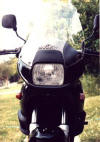 After
repeated collisions in the close quarters garage and several spills on a
Colorado Rockies jeep trail had reduced my front turn signals to a re-glued
dangling mess, I decided that small markers that did not protrude would be the
solution. Lockhart Phillips marker lights provided the answer at a reasonable
price. Found at Chaparral Cycle Supply, ask for part number L122-9951 for black
body/amber lens. White body/smoke lens are available. Chaparral's number is
800-841-2960 or http://www.chaparral-racing.com for their internet address. Cost
is about $13.00 plus shipping. You will need male/female connectors to do a neat
job. For $2.50 at my local electronics store I got Waldom molex two circuit
nylon connectors. These are the same connectors found on the bike. As with any
project, take your time, plan, look, think, go slowly, and always check/double
check. If you have no mechanical ability or are accident-prone, get a mechanical
friend to do this! Please read all of these instructions before doing anything.
After
repeated collisions in the close quarters garage and several spills on a
Colorado Rockies jeep trail had reduced my front turn signals to a re-glued
dangling mess, I decided that small markers that did not protrude would be the
solution. Lockhart Phillips marker lights provided the answer at a reasonable
price. Found at Chaparral Cycle Supply, ask for part number L122-9951 for black
body/amber lens. White body/smoke lens are available. Chaparral's number is
800-841-2960 or http://www.chaparral-racing.com for their internet address. Cost
is about $13.00 plus shipping. You will need male/female connectors to do a neat
job. For $2.50 at my local electronics store I got Waldom molex two circuit
nylon connectors. These are the same connectors found on the bike. As with any
project, take your time, plan, look, think, go slowly, and always check/double
check. If you have no mechanical ability or are accident-prone, get a mechanical
friend to do this! Please read all of these instructions before doing anything.
Remove the stock turn signals. Be sure you
have the electric shut off. Remove the lens cover and then slide the spade
connectors off so that the positive and negative lines can be pushed back
through the turn signal body to be left dangling under the fairing. Whether you
solder wires, crimp, or just tape things together is up to you. Good connections
mean that lights will work.
Examine the Lockhart Phillips turn signal.
The bulb has two filaments, meaning that this turn signal can be used as a
running light and as a turn signal. The filament that burns brightest is the
turn signal, the other, the running light. You will need to test to make sure
which is which. The instructions here are for turn signal operation only.
Isolate and insulate the wire connected to the low watt filament (running light)
- tape it out of the way. Ascertain which of the two wires remaining is ground
and which is positive. The positive wire will make the bright filament burn. The
three wires are black, red, and black/white. The instructions on the back of the
package were unclear, so I tested everything myself to be sure which was ground,
which was low watt filament, and which was the high watt filament. Make sure
that the wiring is long enough for final hook up. Check everything twice! Check
the lines underneath the fairing for positive and negative...BMW ground is
brown. Each side must be hooked up the same way. The plastic male/female
connectors must match up. Check and double check! Make all your connections neat
and tidy. Make a final check with your wires all dangling down; do your lights
work properly and are both sides of equal brightness? Do these lights flash with
their rear counterpart?
 The
hardest part is the drilling of two holes in the turn signal base plate. A large
hole just above the light socket through which the wiring will fit and another,
smaller hole, for a mounting bolt to secure the turn signal to the fairing. No
holes are to be drilled in the fairing. See the diagram for hole size and
placement.
The
hardest part is the drilling of two holes in the turn signal base plate. A large
hole just above the light socket through which the wiring will fit and another,
smaller hole, for a mounting bolt to secure the turn signal to the fairing. No
holes are to be drilled in the fairing. See the diagram for hole size and
placement.
The fairing opening for the stock signals
has enough room to pass the connectors through and to allow space for the wiring
to keep from being smashed against the fairing body. If wires get crimped
eventually lights don't work. When placing the three wires through the large
hole you drilled in the base plate, be sure that those wires are insulated from
the sharp edge of the hole; use several wraps of electrical tape there. Select a
machine screw long enough to be used for mounting the turn signal to the
fairing. Used LocTite or a lock-thread nut. One mounting bolt is and the rubber
base is enough to keep the turn signal from slipping. Place each turn signal at
the same slant and tighten in place. Be sure to use washers with plenty of area
on the backside of the fairing. With the base now in place, put the bulb in,
connect the male/female connectors under the fairing, and check one last time.
Does everything flash nice and bright? Okay, put the amber lens back in place.
All done!
Lockhart Phillips 1-714-498-9090
Addendum 10/1/00
Kenny #604
After reading the above referenced article
in the FAQ and having the exact same problem with dangling, glued messed-up
front signals, I started looking for an alternative to the Lockhart/Phillips
lights also referenced in same article. In a local Pep-Boys automotive store, I
found marker lights (Blazer #C472FA by federal mogul) that were $4.99 each. They
pretty much what I was looking for and identical to the referenced article. The
new signal had one black wire while one of the 2 mounting holes served as the
ground. After removing the old signals, I cut off the spade connectors, stripped
the 2 brown and blue wires, connected the black wire from signal to the brown,
and the blue I soldered to the mounting hole on the signal. (while testing it
worked either way and very well!) A quick trip to the hardware store, bought 2
metric machine screws M6x30mm, .35 cents, these screws were the perfect length
to use with the existing lock-thread nut and washer getting the just-right
snugness so as not to break something. The lights are rubber backed so I only
used the 1 screw on each side, once tightened down it wasn't going anywhere. Put
the bulb in, the amber cover screwed on, no problems. The lights look good
(better than I expected) and work great! In fact, with them being mounted in
this fashion, I can see them operating which may help to get my attention to
turn 'em off! Come on, we've all done it, looked down at the gauges and realized
you just rode 17 miles from that turn with my right blinker on! The job took
about 20 minutes and was very easy, and I spent less than $12.00.
Feedback/Tips:
Q. Got some Lockhart Phillips from
Chaparral to replace my broken, glued, nasty stock front turn signals. I wired
them into the bike to test them, and when I hit the turn signal switch, the
light will SLOWLY fade on and not blink. I can hear the relay wind up (or so it
sounds) but then it won't blink off. Any ideas what the $%*& is up. NOTE: I am
not using the light recommended in the FAQ, but a full lens model that can be
seen from the side as well as the front. Yes, it is 12V, yes I put pos to pos.
and neg to neg.
A1. The wattage of the lights you're installing is different than the
stock lamps. The flasher is a thermal device that works on total current flow
and changes with the draw. Install an electronic flasher rather than the thermal
one. Or match the stock bulbs. Harl #380
A2. Sure is, I had the same problem you need a 10watt bulb. Scott#264
Replacement Stock Turn Signals
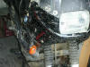
Replacements from KTM
97 ST VT USA. Peter Jensen #233
The KTM flexible signals mount with a 13mm threaded rod, in
addition to the signals you must also purchase nuts to mount them. The stock BMW
signals mount with a small screw on the classic not sure about the GS's. If you
place them right the mount will cover the hole for the BMW mount. You will also
need to thread the wires through the threaded rod (put the nut over the wires
first) and enlarge the hole slightly. They look just like the stock ones but
have a little give.
Replacements from Buell
by Sean-STL
| Part Number
| Description
|
|---|
| Y0503.9
| Right Rear / Left Front turn signal
|
| Y0504.9
| Left Rear / Right Front turn signal
|
Comment: It is a direct match appearance wise. These part
numbers are for the S3 or S4 thunder bolt (unknown year). The parts cost about
$5.50 each and any Harley/Buell Dealer should be able to help you out.
Installation: Leave the harness in the bike and fish it
through the new stock.
Problem-solving after
replacing the Flashers:
by
Flash #412
Not blinking at all?
Problem:
I am replacing my front stock turn signals with
flush mount marker type lights mounted on the sides of my ERMAX
windshield/fairing. The problem is the lights do not flash, they just stay on
when I flip the turn switch. I think the problem has to do with the current draw
of the new lights versus the old. The old lights measure about 2 ohms and the
new ones about 4 ohms. The circuit must be designed not to flash if the
resistance of the circuit is higher to indicate a problem with the light.
Anybody have any insight on this? Can I just install a parallel resistor to
lower the circuit resistance and make it work? Any other ideas?
Common
Solutions:
1.
Check the Bulb Wattage/Voltage is the SAME as your OEM Bulbs
2. Check
your Battery NEXT. See the Battery FAQ
Other
things to check:
-
When my
VR was going south my turn signal
would not blink for left unless I switched on/off a few times and my horn
sounded like Ned Beatty in "Deliverance". Check the voltage going to the
battery just to rule out VR failure. Chris in Santa Cruz, CA #782
-
If you forget to
reconnect the front flashers then the rear flashers will only light, and not
flash, The front flashers of course won't work. I discovered this a couple of
weeks ago when I had disconnected the front fairing for some electric work and
forgot to reinstall the front flashers. Spakur #1117 Icelander in Malmö,
Sweden 1995 Classic Red F650 with 60.000+ KM.
-
Flashers light
but do not flash. I had this problem and it turned out to be a very simple
fix. The wire running to the flasher in question was worn bare where it passed
near the VR (insulation melted from the extreme heat probably!). It was
causing a short. Used insulated shrink wrap and prob. disappeared. Other
possibility is that one of the bulbs is burned out. That's always a simple
check. See if the opposite number of the flasher that glows solid is out. I've
been so distracted by the one that just lights up, I never looked to see how
it's companion was behaving! Sean #1015 Ottawa Canada
-
I had this problem
a few months ago - the answer was a wrong bulb (which incidentally was sold to
me by my local BMW dealer; the voltage was too low. Might be worth checking
whether your bulbs are o.k. walkon40.
-
It could also be a
Broken Relay. Runaway #1259
-
Put a
small resistor in the hot lead that will approximate the wattage of the
original lights and you should be good to go. Don't remember the calc's to
figure out how big the resistor should be. One of these electronic wizards on
this site will be able to help? Bill, #697, Atlanta, Ga.
-
Or...
put some more lights in parallel with your new ones, summing to the stock
wattage. Flash 412 (CO)
On-again, off-again turn signals:
Q. Here is an
odd one: my turn signals do not blink when the engine is off, but work fine
while it is running. With the engine off, they turn on and stay on. I never
noticed this before, but I can't promise that I ever tried the signals with the
engine off before. Is this something I should worry about? Could it indicate
that something else is awry? My battery seems fine... I just topped it off
recently, and it starts the bike first try, every time. (p.s. I have a '97
Classic). Robert in Texas #959 -- Black '97 Classic
-
Pull da bubs out,
rub em on yer jeans, stick em back in and I bet they work just fine. The
difference? Vibration. The flasher is an electromechanical device which is
based on current flow through a bimetallic strip which heats up, opening a
switch, stopping current, cooling down, closing the switch and repeating. If
you have a slightly oxidized contact on your bulb, it will increase the
resistance. It is possible to increase the resistance to a value where the
current flow through the blinker relay is reduced to where the bimetallic
strip doesn't heat up enough to open, but still passes enough current to light
the lights. The positive contact of the bulb is generally soldered with
lead-based solder. It touches a brass or bronze contact in the socket. This
interface commonly corrodes faster than any similar-metal interfaces in the
system. Odds are, it is dirty bulb feet. Take em out and rub them on your
jeans and put them back in. There is only one screw per turn signal. It won't
even take you as long as it took me to type this. (But you still might have a
dirty connection elsewhere in the circuit. ) I'm thinkin' that if the bike
still starts, you have enough juice in the battery to light 50W worth of light
bubs. Flash #412 (CO)
-
Check your battery
and its connections. If the voltage is low or the connections dirty, the
system my flow enough current to light the bulb, but not operate the flasher.
When the engine is running it would then be running off the charging system.
Harl #380
Correct Relay for the Voltage?
Q. My cousins Lars (R11GS, R80GS) and Morten (R11R), both have replaced
the orange blinker glasses with white/clear ones on their bikes and I decided to
do the same on my 97 F650ST because it looks really good. Aprilia stocks the
glasses/lenses (whatever it's called in English) and they were only $7 a piece
including tax. I went to an auto parts store and picked up the bulbs needed.
Regular bulbs would make my blinkers flash yellow which is not legal. Orange
bulbs are ugly and defeats the purpose of clear glasses as they would look
orange. Osram makes a bulb called "Diadem" which is clear with a hint of blue
and orange, but basically clear and they flash bright orange. They come in packs
of two and cost, get this, $29 a pack....I needed 4 bulbs - $58. Came home
and replaced the old bulbs. WTF ? Is the relay singing on the last verse
?.....Shit, stock is set up with 10W bulbs and relay. The Diadem bulbs are 21W.
Found a 2-pin, 2x21W relay made by Tridon, $21. Installed everything, works like
a charm - with the engine off that is....when the engine is running it flashes
WAY to fast, but not very regular, two or three quick flashes then a couple of
slow ones. It seems the speed of the flashing increases with the RPMs. What I
discovered though, is that when I apply the brakes - the flashing speed is
PERFECT....if the lights are off....turn on the lights and flashing speed drops
to normal - press the brake lever and it speeds up....sigh ! Only thing I can
think of is that the new relay lets too much current pass, but my theory has big
holes because if this was the case it (the speed) should drop further the more
lights I put on, right ?! So $107 later I have flashers that's not working
properly How do I cure this ???? #s
Aprilia glasses: SR50 ($7 a piece)
Osram Diadem bulbs: PY21W - BAU15s ($29 a pair)
Flasher relay: Tridon EP-20 ($21)
-
It sounds like your relay is very dependent on voltage for it's flash
rate. If the voltage is low, the flash rate is fine. If it gets higher, the
flash rate speeds up. The reason your voltage changes is because of the way the
voltage regulator handles the increasing electrical load - things like the
headlight, brakelight, and flashers. (The wiring harness and electrical system
does not have excess capacity, and some are particularly sensitive to changing
loads and poor connections.).
Failed Flasher Relay?
Q. I have installed flush mount turn
signals about 6 months ago. When I installed them I could hear the flasher unit
(for lack of better term) working over time to blink the lights. I have found
out today that it has quit. Had enough, passed on, died. There are the Lockhart
Phillips type and was wondering if anyone else had this happen, and if so what
"flasher" specs should I replace it with. (I am not an Electrical Engineer and
will not try to fake it.) I am assuming the resistance of the new bulbs, wire,
connectors, etc. have increased the resistance and therefore caused the
"flasher" to work harder and now thus die. Any ideas?
-
You need a relay that can handle the bulbs you've put in. If the new
bulbs are 21W and the old were 10W (like on the classic), you need a relay that
takes 2x21W instead of 2x10W. Thomas849 (Norway, '97ST).
Turn Signal Warning
Beeper
Q. I was thinking to design a simple
beeper + LED to remind myself of the turning light. The relevant wiring diagram
is
Here. This shows two wires going to the turn signal indicator lamp on the
dash (part H9031): a BLRT (blue/red) wire and a BLSW (blue/black) wire. Power
(after going through the flasher unit) flows into the turn signal indicator lamp
on the BLRT wire when the left turn signal is activated, and on the BLST wire
when the right turn signal is activated.
1. How is the turn signal indicator lamp lit w/o having a ground?
2. What keeps current flowing from, say, the BLRT wire (left) through the
indicator lamp, into the BLST wire and lighting the right turn signals? The
diagram shows directions of flow. Are there diodes somewhere to prevent
backflows? Perhaps "Keys to Schematics" would help. It is at:
A1. What you need (for the LED) are two diodes (1N4148 for example) a
resistor (to step down the 12 V.) and (of course) the LED. The two diodes are
necessary since you want to connect left and right to the same LED but you don't
want the current to flow back and turn on the four lights at once. If you don't
need it, you can avoid to connect the buzzer (a 12 V. Piezo beeper). Just
remember that diodes and LED have a polarity that you have to respect. The
resistor value depends on the LED. I am leaving for a trip in a couple of hours,
so I don't have time to give you all the details. If anybody is interested, I
can fill in the blanks. Here is an ASCII art schematic
Left ----[1N4148]--+
+--+--[Resistor]---[LED]-+-- Ground
Right ---[1N4148]--+ | |
+---[12V. Buzzer]-----+
Giovanni.
A2. Use a _small_ 12 volt indicator lamp available in green and other
various colors and sizes from Radio Shack instead of an LED. Since there's no
polarity involved, you can connect it across the two positive wires of the left
and right blinker. The tiny indicator lamp will ground back thru the much larger
filaments of the blinkers that are off. I've had this setup on my Classic for a
couple years, with the indicator bulb as high as I could get it, tucked under
the windshield cover. Todd #389.
Fliplites
- Here's a possible product for those of us who
go offroad or otherwise want to protect the turn signals:
www.fliplites.com Maybe with the
Touratech mini blinker? Todd#389
Lighting: Other Sources &
Reviews
Modulators
Generic
Modulators:
-
If you're
interested in little project, you could make your own modulator, fairly
cheaply. See
http://www.buchanan1.net/nother_mod.shtml. or Google your way with
"headlight modulator" motorcycle. I'm soon to do front and taillight, with
superbright LEDs, and markers in blue built into the turn signals, once I find
some clear lenses for them (blue really jumps out at you, even in daylight).
Aleksander, Dubai.
-
Generally
speaking, the modulator itself is legal in every state. I would think you
would want it to work when on low beam - as it makes the headlight alternate
between low and high. I would also think you would want it to stop modulating
when you put it on high beam. I don't know much about the light sensitive
switches to deactivate the system, but I'd think a on/off switch for the
modulator would be necessary. I don't have one of these, never ridden with one
and don't plan on installing one, so none of this is from experience, just
what I've read, heard and seen. What I had read is that the switch from high
beam to low beam kept both filaments from reaching max heat and extended the
life of each. Now I guess I'll have to look and see where I saw that.
Modulators have been around for over 15 years. I don't see them getting that
popular in 5 years. I see the Hardley crowd interrupting their new bike
electrical systems to be able to turn OFF their headlight while riding - and
they have a more powerful lobby (think tariffs in 80's and getting rid of
helmet laws). JMO Gar, '97 classic, red
-
Actually, AFAIK
it only works on the high beam and the 'flashing' effect is from the duty
cycle of operation, from 100% to around 17% power, so that the filament is in
continuous operation. To switch from high to low would probably kill one or
the other filaments in fairly short order due to the on/off surge of current.
The photo cell is to prevent modulator operation after dark (or near-dark). It
may be federally required, and certainly is in some states. I had a KRIS on
one of my '81 RT's and liked it. Hal #15, Glide OR, '97 F650ST/Sputnik, '97
Ural SportTourist, '87 Honda Helix/Friendship (Sharon's), '74 R90/Ural
-
It's high beam
only, w/a light sensitivity sensor. It works when headlight is on bright then
the sensor registers daylight. You can put in manual switch but then you're out
of code. It doesn't switch between low and high just modulates intensity of
high. davidhpark711
-
Be aware of the
downside to running your motorcycle with one of these devices.
1. Most cagers...and Law Enforcement will perceive YOU as an emergency
vehicle. I state this from first hand experience, one of the guys I ride with
has said device and on more than one occurrence when he used the modulator,
cagers have dam near killed themselves...and us...trying to get off the road
as we approach from the rear. Also we have been pulled over, as local LE think
we....are impostors ( read pretending to be emergency vehicles)
2. While a legal device, not everyone knows this. refer to #1. Perhaps not
worth the hassle to explain to Mr Police Office that it is legal.
3. Works great to bring attention to your operation of a Motorcycle.......
refer to # 1 and #2 :-).
The upside is all the above...with the exception of spending time explaining
and helping your buddy pick up his/your bike after the melee of having Grandma
Betty dam near killing ya as she tries to get out of the way on that two way
back road:-)
I have considered installing one myself, however after first hand experience
with the above I don't feel it is worth the extra attention it brings,
IMHO:-).... I ask any riders using one to turn it off...on low beam when
riding in a group. If your riding alone, you may still have some of the above
happen :-). Ride in the daylight with your high beams on.....the F650 has the
nice little left bar lever to flash the lights when needed....neither the
Honda or HD I have have this :-)
For rear visibility. Add some LED lights. My worst fear is the " but I didn't
see the motorcycle" after the M'fer runs me over from the rear with the
Excrushion/Suburban/Tank thangy:-) Thumper, Austin TX, 02 Dakar.
-
Hurt report said
greatest danger is left turn in front of me and this thing will help. There is
a Federal law that supersedes all state laws and makes this thing legal as
long as it conforms to the Federal specs. Law also states from what I can
gather that this cannot be a "stock manufacturer item" i.e. - can't come on
new bike. (Wonder what lobby that came from) One company "Kisan" offers "plug
in" models. I imagine that within 5 years you will see these things on 50+
percent of bikes. I know that being seen is my biggest concern and this will
really help. May get one for taillight also. '01 F650GSA & 9c1, Memphis, TN.
-
Since installing
my aux lights last fall, I'm finding that SUV riders are giving me LOTS of
room. That is, when they look my way. (Obviously we can do nothing about those
who fail to look: these are situations where cages kill cages) Cages that
start to pull out, then look, are stopping right in their tracks, even when I
am nearly two blocks away on a 35mph street (i.e., far enough that they would
dash out if I were in my truck). My brother observed that the yellowish tint
to my lights, contrasted with the white headlight, is a real eye-catcher:
nothing else in the traffic flow looks quite like it. I've seen just a few
bikes with modulators, and I'm not convinced they caught my attention any more
than bright lights. But then again, as a rider I tend to notice just about any
bike . . . Anyhow, aux lights might be a possible safety aid. That, and they
are handy at night! The below picture gives a rough idea of the result, though
it is much more blinding in person, especially when viewed more head-on, or
from a distance. I could snap some more "representative" pics if anyone is
interested. Scott, ID #1244
-
I have one and
use it a few times a week, like a horn, when I see a problem "up the road". It
really does get people's attention! I also use it on lonely foggy rides around
dusk and dawn, I never tail anyone with it on though. No need to be rude. I
use it freeways, period. Bikers are at such a disadvantage here, everything is
fair IMO. Joe
'01 F650GS Inmate No. 1065
-
I have commuted
to and from San Francisco on my motorcycle and some times in my car. On one
occasion a motorcycle with the modulator was behind me while I was in my car
and it annoyed the heck out of me. I now have additional driving lights on the
F and when the commute gets nasty I use them. I think they do a good job of
bringing attention to my motorcycle and me. The left turn figures are
interesting to me. If the person turning left is trying to squeeze in just
behind the car you are following and you’re out of site? At this point the
person turning left may be very focused on the next auto trying to figure out
if they can make it and ready to mash the accelerator. I have noticed several
times when traveling behind another auto approaching an intersection and
looking through or around the auto the person turning left probably can’t see
me. It is my belief some of the left turn accidents involving motorcycles
might be avoided if the motorcyclist try’s to makes sure he or she is in a
spot to be seen by a person turning left. When I approach a situation that may
include left turners coming at me I make dam sure I’m in view and then DON’T
COUNT ON THEM SEEING ME.
Will in CA
-
I've been using
the Pathblazer(?) for about a year now. No question in my mind that I'm
drawing attention to myself in the interest of safety. As far as I'm
concerned, outside of insurance, it's one of the smartest and best valued
C-notes that I've ever spent. I'm considering the flashing, flickering brake
one as well. Derek, Maryland, USA, '99 Classic F650. Derek
-
www.kisantech.com &
www.signaldynamics.com seem to be
the most widely available. Since it can be really irritating to the driver
sitting in the car ahead of you of having your beams flashing continuously in
his rear view mirror, I'd suggest just switching it off when in close
proximity to the car in front of you. I see it's best value when approaching
oncoming traffic. Each site also allows a printout of the federal standard in
case of legal problems. 2001 F650GSA Chicago, IL Logan's Ride
-
I'm about to
install a headlight modulator on my '03 CSA. Of the three I've found
available, here is my opinion: Kisan Pathblazer: simple, straightforward, but
basic. Daylight sensor mounts upwards, tied to brake or clutch cable. Some
concern about flex, since this unit was designed for a naked-bike type
headlight tied into the steering head. High beam installation recommended.
$100. Comagination VisiPath: again, simple, plug-in, but I question whether
there's room inside the CS's very small high beam housing for the parts.
Again, the daylight sensor is meant to be mounted upright, as for the Kisan.
High beam installation recommended. $75 (I think). Signal Dynamics: large unit
needs to be mounted outside the housing, but OK since the housing is so small
anyway. Daylight sensor is mounted pointing down (in contrast to the other two
types). There is a control switch for off and two modes of modulation. This
unit can be wired into both the low and high beams, as well as into the horn
switch to modulate the high beam for 2.5-3 seconds, even if modulation is off.
$90. My choice will be the Signal Dynamics unit. Colorado Tom: 2003 F650CS.
-
I bought one of
these on EBay last year and I have been using it on my high beam. I commute on
my bike and I notice a difference with drivers behavior. Especially if you aim
the bike at cars pulling in your way. The modulator varies the intensity of
the high beam and does NOT switch between high and low. It has a light-sensor
that prevents it from functioning in the dark (including tunnels) I strongly
recommend it. Don Carnage, Inmate # 1243, 1997 F650 - Red. Southbury, CT.
-
I installed mine
(on a 97) to modulate the low beam, as I do a lot of in-town riding & didn't
want to blast people with a high beam. I also put a waterproof switch in the
dash so I can turn it off when I'm at a stop light sitting behind someone.
Mine's not up to code, as it has no automatic dimmer for when it gets dark. I
think it really helps people notice me, and they are easier to pass on twisty
backroads because they're not sure if I'm a LEO. I found it on the web
somewhere for about $40 from a guy who makes them himself. His web site
included the text of the federal reg that states these are legal. I printed it
& carried it with me 'till it turned to dust. Never was an issue for me,
though. '99 F650, WA. Scott S in WA
-
I have the Kisan
Tech Modulator. It works great. Haven't had a bulb failure in 3 years.
Modulates the High Beam which is the way I want it. If I'm trying to get
attention, I want everything going for me--so high beam it is. If I'm in close
traffic and I don't want to irritate drivers, I just go to low beam for a
while and that turns off the modulation. The Kisan Pathblazer is easy to
install, high-quality and meets federal standards. In California, where you
can do lane sharing (lane splitting) it really helps cars see you coming
between the lanes and often they will move over a little to let you through.
Drivers in CA are used to bikes coming between the lanes during heavy traffic
conditions.
www.kisantech.com Lake Tahoe, Nevada.
Dick#420
-
Here is a link to
the federal law on headlight modulators. I printed it and will keep a copy on
my bike just in case!
http://www.soundrider.com/store/kisan/HMFedLaw.htm Don Carnage, Inmate #
1243, 1997 F650 - Red. Southbury, CT.
-
My modulator came
installed on the bike - never breaks down, reacts according to traffic
conditions, changes with ambient lighting conditions and is legal in all
states and countries. What's more, it is not hellishly annoying to the traffic
in front of me.. it is, of course, the fingers and thumb of my left hand when
used in conjunction with the high beam switch. Whenever I feel uncomfortable
with the way a vehicle is behaving I switch the high beam on. and off again.
and repeat. At times, when I feel very uncomfortable with the majority of the
other traffic, I will just leave the high beam switched on. and then switch it
off when I am following someone closely. Very simple, very effective and
already installed....Lance, #1303, '01 F650GS, '96 G650ST. y_kiwi
Helmet Lights?