Where Is That Connector the Heated Grips Attach To on a GS (For the Heated Grips FAQ see Hot Grips Installation FAQ)
What about an Electrical Junction Box or Connector for Electrical Accessories that is NOT the Accessory Socket?
For Accessory Socket-specific Questions see the Accessory Socket FAQ
For all other Misc. Electrical Questions refer the Classic Electrical Misc FAQs
For Voltmeter Questions refer the Aftermarket Voltmeter FAQ
What is the Capacity of the Charging System
edited by Adam #1001
August 19, 2000
Well it seems to be a problem with the first F650GS's released from BMW, and it appears to be world wide. However, there have been no reports about this problem from anyone in USA yet.
According to BMW, the starter relay fuses together due to low voltage in the battery. When this happens the starter is continually engaged and will continue to try an start until there is not power left in the battery. Some folks will find this problem reminiscent of the early K bikes.
If you encounter this problem, you must do something immediately, since the starter is not designed for continuous load, and possibly might be damaged. You'll find the relay under the tank dummy cover, in front of the battery. To get access to it, you have to remove the cover. Once you have removed it, hit the relay with a screwdriver or something similar, then there should be silence. If not, remove the battery's ground connector and call the local BMW service number. In any case, you should make your dealer order and mount a new relay. It's a case of warranty, and it should cost you nothing.
The only thing you can do to prevent this is to keep you battery charged. Don't lug the bike around town. Basically keep the RPM's up so the battery is getting a charge. You may even want to consider the Battery Tender that has the BMW Accessory connector on it so you can charge you bike while your not riding it.
Addendum 10/1/00
It has come to our attention that BMW has new starter solenoids that will not fuse the starter relays. This is suppose to be covered under warranty and a recall is suppose to be announced for all countries with the new GS and Dakar except the USA (They have their own problems).
Adamx 1001: my GS had a faulty one in November 2001, so there's still a few problems.
The connectors that the grips and switch attach to were buried in the wiring junction box that's between the battery and the front of the frame, in front and under the more visible connectors in this area. I couldn't see them, and had to fish them out by reaching around for them.
I'm not sure if having this wiring already in place makes installation that much easier--it may be possible to get by with removing only the part of the airbox that's in front of the air filter (which would be good since getting the airbox seated fully on the throttle body isn't easy), but you still need to remove the three painted panels, the battery, part of the airbox, and the cover to the junction box.
Oh, and you need to install a 7.5A fuse in the bottom slot to use the grips. The kit doesn't include one, but the factory toolkit does :~)
Does the F650GS
BMW accessory socket kit fit a Classic?
by Harl #380
The GS/Dakar kit is different from the Classic kit. The Classic kit connects to the battery directly while the GS kit connects to a plug on the wiring harness. The socket mounting is different as well.
Notes:
Mine came from an R100GS I just made the wires a little longer, it works. James#848
Heated vest and BMW accessory plug installation
by rpozak (Rod CO '02GSA)
Tired of freezing my kahunas off here in CO this winter, I got a heated vest and bought the BMW accessory plug. As usual the BMW instructions made me want to throw something.
Note that I use the word “clip” to denote a mechanical fastening device and the word “connector” to denote an electrical connecting device. This is very important.
Take all faux tank panels off. It will be a lot easier. Refer the Fairing FAQ GS.
Install the accessory plug on the left side of the bike as described in the BMW instructions that came with the kit. I plugged-in the wiring harness to the accessory plug first, and bolted the plug to the bracket first since it looked like h*ll to do it after the thing is bolted to the bike. Two screws and some careful wire routing and you are done. Now sit back and wonder how you will plug and un-plug things without messing-up your clutch cable.
Route the wires from the new accessory plug to the right side of the bike. It is now time to toss the BMW instructions since they are 110% worthless from here on out. Trust me.
Slip the black fuse box (right side under seat near end of faux tank) off of its holding clip. You will have to push the little tab on the clip, otherwise you can pull with all your might and it will not slip off.
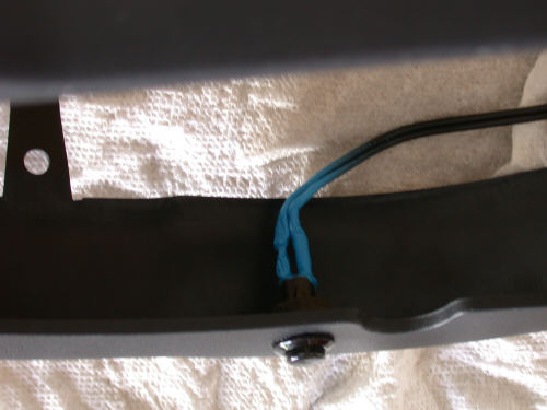
Locate the accessory connector on the right side of the bike fastened by a little screw to the inside (closer to the engine) of the stamped metal frame-like part (painted black). You will see a white connector and a blue connector “clipped” together. Leave the blue one alone as there is no telling what it does.
Unplug the female end of the white connector from the male end. You have to squeeze the tabs on the side of the female end. Use both hands unless you are some kind of mutant with very long fingers.
Remove the little screw holding the white and blue connectors to the black frame part. Don’t worry about getting this little screw back in; it is easy and it is the least of your problems.
Cut the cable tie that goes through a little hole in the black metal frame part so the wires are loose and you can move the white and blue connectors around. Cutting this cable tie is important, or you will never do what comes next – which is almost impossible anyway.
With your extremely long, mutant fingers, “clip” the new white accessory plug (male end) to the side of the existing white male end connector. This is not easy my friend but it can be done. Have patience. Do what Flash does and have a Rum & Coke. Examine you wire routing first to be sure nothing rubs against a hot engine part like mine does. You should see two male connectors facing up and ready to mate with the females (connectors).
Plug the white female end of your new accessory plug into the white male end of the connector closest to the blue connector.
Plug the other white female end into the other white male connector closest to the engine.
Put the little screw back in that holds the connectors to the black metal part, put the cable tie back on that holds wires to the black metal part, clip the fuse box back in, carefully check your wire routing (especially that brown fuse hanging from that wire there) and put cable ties where appropriate.
Start her up and plug-in Christmas lights (wish I had a digital camera, but you can imagine).
Feedback:
I did this job about 10 days ago, and for the most part I agree with your description. I disagree with #6 though. It's a tight fit, and yes, alien fingers would help a great deal, but it can be done if you bring your right hand up underneath the wiring connection and guide the new wires in. I don't have long fingers but was able to install this part fine once I sat back and drank a Guinness while contemplating the German/English/Intuition directions without cutting a cable tie, and removing a part that I didn't need to. If I can offer any advice, it is to make sure you run the wire harness across the top of the seat area without pinching it where it doesn't belong, or avoiding one of the many types of wires the directions say to avoid, which seems to be all of them. The accessory harness is longer than necessary, and the instructions are cryptic, but make perfect sense in hindsight. Stuflinn
Ummm, this was MUCH easier for me. My bike had heated handgrips on it when I bought it and the inline pigtail connector was apparent once I got the covers off. The install took me about 10 minutes. Did I do something wrong? I haven't tested the outlet yet... I wasn't thinking that far ahead but everything else works great... except for the oil leaking out of the airbox, the radiator leak, the dying at stops, the not starting in cold weather, and the goo under the oil cap. chppdlvvr
I think mine is different. I did exactly what you said (wrote). What I see on my 2002 Dakar is the white and blue BMW connections. The blue one is connected to something while the white is open and exposed, nothing connected to it. These are clipped to each other. I assume that I must connect my power socket wire harness to this white connector. There is only one choice as the harness has male and female side, one of each. So I make the connection, what do I do with the other white connector that has no where to go? I don't have my vest yet, so I cannot test my new installation. I have a feeling I did not get everything plugged in that I needed too. HELP. I guess I got it right, my vest that I received in the mail today heated right up. As far as the directions, without heated grips on the bike, I would simplify to: plug white connector of new socket harness into the white connector that is joined to the blue connector under right side fake gas tank. There is only one white new connector that will fit into the existing connector. I got it and that's what matters. The Dugger.
I had similar thoughts when I installed mine. This was the first time I'd done any work under the plastic on my F, so I had no prior info to go on. I think you've got it so far, the white connector goes into the existing female plug. The female connector on the accessory outlet now connects to the side of the original open outlet, thus extending it. I then had this other connector all by itself. It stays that way. It contains the fuse for the assembly, and just hangs there. I tucked it away, and secured it with one of my cable ties. Of course, there is no way to know if you did the job correctly except to test it. I plugged in my Battery Tender and hoped for the best. No explosion, no blown fuses, so I musta figgered it out, and it sounds like you did to. If you had heated grips, you were supposed to unplug them, and then re-plug later, but I don't so I didn't dwell on that part of the instructions. Stuflinn
For the Classic Sidestand Switch Bypass Procedure, see the FAQ
Problem 1: Side stand switch popped off
Pelle, Sweden
Riding down the road, motor just stops. Bike will start in
neutral, as soon as I shift into gear, motor cuts out. I find side stand switch
is jammed between, exhaust pipe and mounting stud, melted. I can still move
metal part of switch to get me back on the road. What are others doing with side
stand switch? Can I just cut the wires and wire together?
Solutions:
According to
electrical diagram wires from sidestand-switch are connected:
Brown - ground (negative)
Brown/Black - gearbox-switch
Brown/Violet - Motronic-relay
Without having bike available for confirmation I believe that Brown connected to
Brown/Violet is the way to wire it without the switch.
Note - There may be some discrepancy between the wire colors shown in the service diagram, and what is actually on some bikes. See below for another solution:
Ok, there are three wires: Red, Brown, White... I removed the kill switch then tried jumping the wires.... after a while I found that the White & Brown jumped will disable the side stand kill switch and allow the bike to run properly... Do Not use the RED wire IT WILL NOT WORK PROPERLY.
Wild Willy, CG# 1995 '01 F650GS, Edmonton, Canada
Problem 2: Sidestand Switch Warning
Andy Leeds UK #982
(For an 1150R) My outfit has no sidestand (it only falls over if you
really try hard!) hence the switch that kills the engine if the sidestand is
down is overridden. I know a few riders also do this so they can start the bike
on the stand. Take care how you do it. I am assuming that the FI on the F is
going to work the same way as on the R. Just ignore me if this is not correct.
The circuit looks simple. Power from the ignition switch, through the kill
switch (closed= go), through the sidestand switch (closed= go) to the fuel pump
relay then to the motronic unit. Looks like a simple check at the side of the
road, no fuel pump at ignition on, you check the continuity. If there is a
circuit, check the relay. If the relay is OK, its the pump, so call the RAC
(Pick-up van.)
Not correct! The motronic unit seems to back feed about 1.5 volts down the line
to the relay when the ignition is on and the switch is open and/or as the unit
shuts down. This needs to be overcome by the power coming the other way to get
the relay to close and give you the fuel pump function if you close the stand
switch after ignition on. If your sidestand switch or sidestand switch bypass
wire is not perfect (mine had water in the connector) this is taken as sidestand
down, so the bike won't run.
When checking, you need to pull the plug off the stand switch, jump the pins
with thick wire then check there is zero current until the ignition is keyed. At
this point when the ignition is keyed, if that's the problem the fuel pump will
prime.
Three hours at the side of the road, on the truck and in the garage, all because
a 2 pence connector let in water and Bosch have some weird features in the
electronics! I think the back feed is a test signal that allows the unit to log
different faults for sidestand down, side stand failed open circuit or to
ground, relay open circuit or failed to ground (useful if you can read the
memory).
On the up side, the RAC orange van guy seemed to know something about FI, his
mate that he phoned knew BMW bikes and the recovery guy knew how to fasten it
down safely. Good service IMHO.
GS Horn stopped
working?
For Aftermarket Horns and Horn
Installation Tips see the FAQ
Symptoms: My 650GSA's horn has stopped working. I press the button, and
no honk. I've checked the fuses, and they all look fine. So, now I fear it's
going to entail pulling off body panels to trace the wiring in the middle of my
apartment parking lot. So, before I start pulling pieces off, I figured I'd see
if anyone had any suggestions as to where to look specifically for electrical
problems? I figured a good place to start would be the horn itself. Everything
else on the bike is working just fine, so I'm thinking it might just be a
problem with the horn itself, but I'm not sure.
Likely it is the cheap horn assembly itself. I'd suggest putting 12 volts to it and see if it beeps, but if you cannot even FIND the horn (probably under the headlight cowling between the front forks, likely visible from the underside) you should probably take it back to the dealer for a quick look. After all, it should be covered under warranty, right? Likely a wire disconnected when the bike was turned hard right or left. Sometimes they are installed without enough slack or get caught on something when the bike turns - not a lot of room under there. Todd #389
Well, I spent Sunday pulling apart the front of my 650GSA, and was able to finally narrow down my non-functioning horn to an open in the ground wire coming off of the horn. So, it looks like it's gone wrong somewhere in the middle of the wiring harness. Not feeling brave enough to open that up and look further, I put everything back together again (hey, my bikes not Humpty Dumpty :'). Jasson, Seattle.
There is a threaded ground point somewhere down the frame. Just buy some 2.5mm cable, a couple of crimps to fit the spades on the horn, a crimp on loop and maybe a short bolt for the earth point. Run the wire under the tank area and onto the earth point. Good as new. Remember to cable tie the cable to the frame so it doesn't chafe through. Andy Leeds UK #982
Q. I have come across an embarrassing problem. I recently had to disassemble the
rear frame, including disconnecting all the wires. But I did not pay enough
attention to the set-up before I started. I have now completely re-assembled the
rear frame but I have 2 loose wire connectors (coming from the main frame) that
don’t seem to go anywhere! They are just lying there right next to the fuel pump
underneath the seat. The bike seems to be running fine without them being hooked
up anywhere (I have checked all lights, ABS, etc.) Are these just duds that are
there for accessories and the like or do they actually go somewhere that I have
overlooked? Please check under your seat and tell me you have those lose wires
there as well! I have the 2002 Dakar w/ ABS brakes, Australian model.
One of them is a flat white connector (I think it has 4
'prongs' inside the connector). Looks
like some kind of main power lead. The other one is black and is more fancy with
the little wire spring to hold it in place when connected. This one looks
like it is for electronics rather than power.
A1. One may be a service port. My ABS equipped GS has the large
square-shaped connector with the spring. 1 Green wire, 1 Gray/ yellow. It is not
in use on my bike and not sealed of from the factory- now it is sealed. Haakon
#626(Norway-F650GS).
A2. The other may be a connector for Heated Grips
Q. Spare electrical connection. I have just dismantled my 2001 GS to measure valve clearances and upon reassembly I noticed a short (perhaps 2 inch ) electrical cable c/w a 2 round female plastic connector coming from the harness that powers my fan. In fact the connector is located directly above my fan. I have doubled checked and cannot find a spare male connector within the short cable distance, so I just continued on and buttoned every thing else up and she fired up no problems. Does anyone else have this spare connector? No voltage, however 10 Ohm resistance, brown cable and white with a blue trace cable.
Air temp sensor (from the air snorkel)? Raymo #1173
The MoDiTeC connector? If it's cylindrical, about 2" long, 1" diameter - then that's it. It snaps into a plastic "U"-shaped holder by the radiator. The BMW mechanic connects his diagnostic computer to your bike's engine computer via this connector. Raymo #1173
Got a voltmeter? Is it hot or not? i.e. is it LIVE?
I just checked mine from the top with a flashlight (at work), but not very well
(didn't take the cover off)- it's cold outside. I found a brown/orange with a
blue/white that was connected to the fan. I also found a brown/orange with a red
wire that ran near there. I did not find anything loose besides the charger
connector that is black and unwrapped.
Let me get the info straight:
It's on the right side of the bike, in close proximity to the fan
It's a wrapped pair of wires with no connector "hooks", just open female ports
i.e. [UU] not |uu|
The color is Brown/White and Blue
The wires carry no power.
chppdlvvr
You said the fan was hooked up OK, BUT: The supply to the fan comes out of the MoDiTech harness near the round plug. From the bigger bundle of wires it is 2,5 inch long and ends in a oval plug with two female holes. The wires is one brown and one white with a blue tracer. It then is connected to the wire from the fan. The connector from the fan is clipped to MoDiTech connector clip and hidden behind it. If you have the right side panel off it is seen clearly. haakon#626 (Norway, F650GS).
Thanks for making me look again, sure enough I couldn't see for looking
I found the other end for my missing connector I was looking for a flexible wire
and connector and there in front of me fixed to the fan body was !!!!. Sorry for
the run-around and thanks for the help.
Mystery (unused) Connector Under Seat?
On my 2002 Dakar there is an unused connector under the seat... It's in this pic
You can see it with
the red circle... what is this connector? My bike has ABS but not heated
grips... could be this for optional heated grips? zippo
Short Answer: We don't know. If you find out and have it very good authority, let us know!
I am not absolutely sure re this, but it is not for the heated grips OR the 12V plug. I have both, and that connector is still not used. My mechanic believed it was for the BMW road- computer, but was not sure. The 12V plug come (if you by it from a BMW dealer) with all the wiring and connects to one of the connections at the fuse cluster. What about the theft alarm? It is a bit strange, I measured the voltage on that connector and with the ignition off it was zero. With ignition on it was 6.4 volts DC- bike running or not. I tried the direction signals and everything else, but it was no change, 6.4 volts. I used a high resistance multimeter and that might fool me. Haakon#626
No, that's not where
the BMW cycle computer plugs in, either. The cycle computer plugs into the same
connector as the heated handgrips, which is located further towards the front of
the bike (by the fuse box). Bonnie #1158 -- Northern Illinois -- '02 F650GLA
Electrical Junction Box or Connector?
Q. Does anyone
make some type of junction box where you can get power from the battery
at an easy place? It is a PITA to keep going to the battery under the plastic to
get a power source for accessories like additional lights, radar, GPS, heated
gloves, communicators and the like.
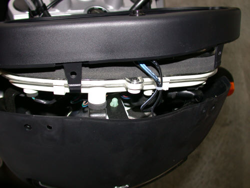
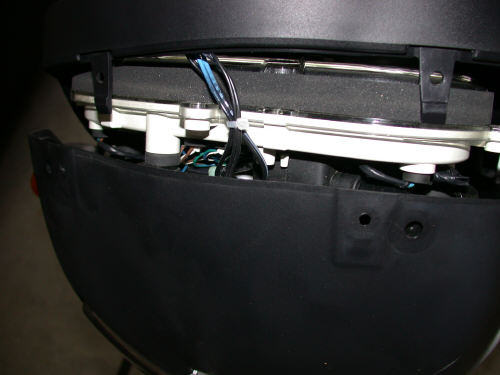
A. Down on the right side (when on the bike) if you take off the body
panel you will find a junction box. This is where you plug in your BMW headed
grips and accessory socket. It was an expandable connector. You can daisy chain
multiple add-ons together to build a big chain. The connector is a PITA to get
to tough as it is behind the frame. (It is anchored to the inside of the frame
by a screw).
If your looking for an electrical "box" you can find it.
Take off the side panel that covers the air box, look along the "horse shoe" that the middle body work is screwed to, along the "horse shoe" you will see a small silver colored screw. This screw holds the connectors in place.
If you take the screw out you should be able to move it enough to use it.
I don't have small
hands and I was able to do it. PQBON
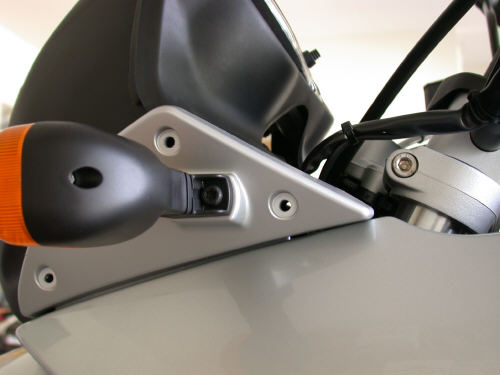
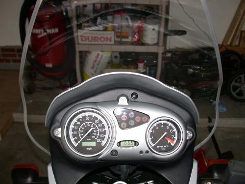
What is that "Faux" Button beneath the Cut-off Switch
My dealer said that the show model of the GS when launched in Munich had a light switch there. Does anybody know if there is a really simple place to connect a light switch (like a connector that is in the loom but never utilised)? Vince #695, UK
by Haakon #626
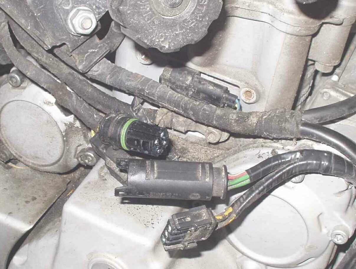
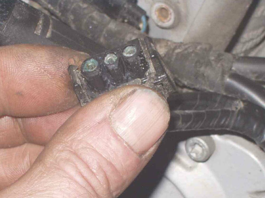
The connector for the
generator output, VR input, had a distinct green, copper oxide, color inside
despite me filling it with dielectric grease just a year ago! The connectors are
behind the small plastic "cover" at the bottom of the cylinder, right- hand
side.
As a preventive action I cleaned ALL connectors with contact cleaner and a
toothbrush/ cotton wads and then used CRC 6-66 all over (a SPECIAL type
developed for boat use), before I filled the connectors up with di-electric
grease. The VR contacts had NOT been cleaned properly before I used the grease
so I guess some water was "trapped" inside the connector. The contacts that has
been given the full treatment is nice and clean!
See also
(Classic) Voltage Rectifier FAQ
but the symptoms of failure are the same. Failures haven't happened on the
GS/Dakar (yet) though!
Garage Door Opener Installation
from
bbb986s
silver/black '03 F650GS.
Based on a post from another forum this is a simple hack to have a
convenient pushbutton switch available for your garage door opener. I placed the
switch in a place where rain is less likely to get to it.
Parts:
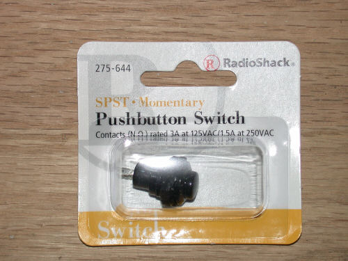
Radio Shack momentary pushbutton switch part #275-644 (black) or 275-646 (red),
a 1/2" drill bit,
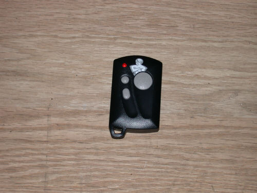
a micro sized garage door opener,
soldering iron and solder.
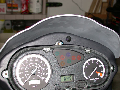
|
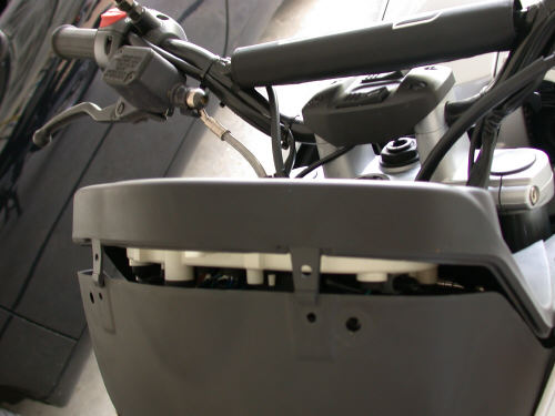
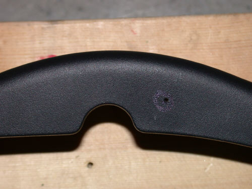
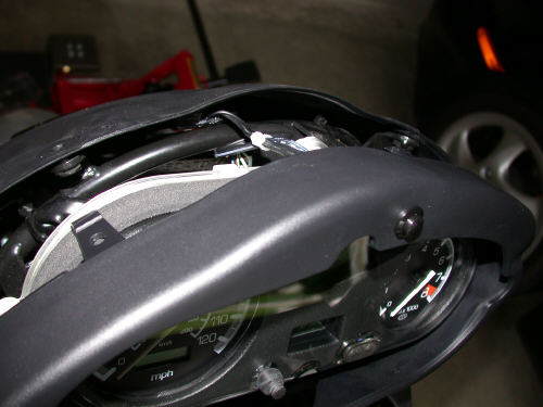
Remove 3 screws to take off the silver shroud surround on the instrument cluster |
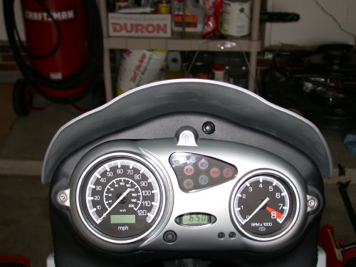
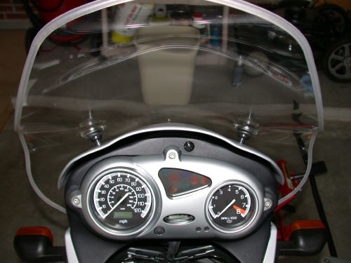
Remove 3 screws to take off the bug screen, then take out the 2 plastic screws with the expansion sleeves |
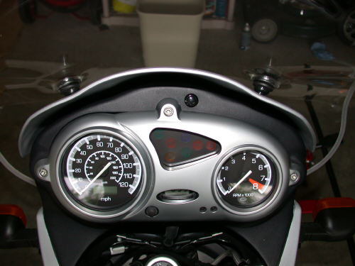
Remove the rear two screws on each side so that the black plastic surround will come out. It removes very easily |
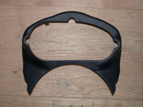
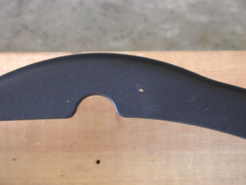
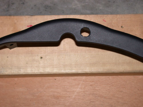
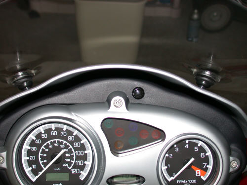
Remove the black plastic surround |
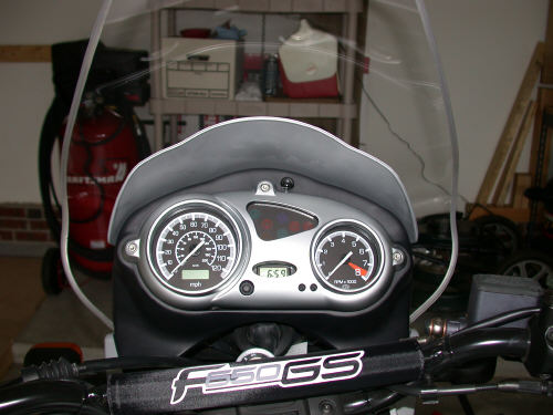
Black plastic surround removed |
|
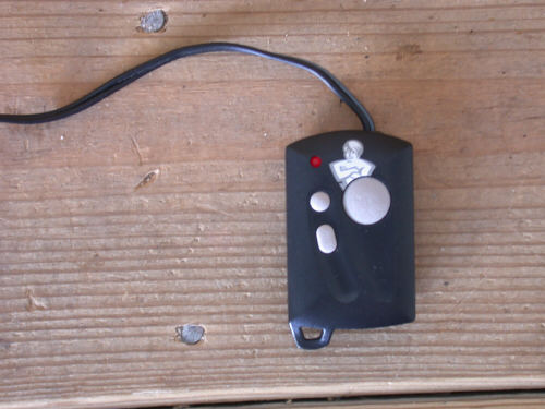
Radio Shack momentary
pushbutton switch |
You will need to drill a 1/2 inch hole |
Drill a pilot hole first. Then, drill progressively larger holes until you reach 1/2 inch diameter. Be careful, the front of the plastic is very soft and scratches easily. |
Consider covering it with some some clear packaging tape or drilling from the back instead of from the front. |
You end up with a 1/2 inch
hole. Take your time, don't make any mistakes. |
|
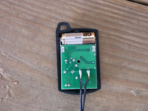
Micro sized Genie garage door opener fits well. You might be able to use the slightly larger mini size instead. This one has three buttons, I used only one. For those of you inclined towards symmetry, drill another hole and wire up an additional switch. |
Open the garage door opener and solder some light gauge wire to either end of the switch of your choice. Switches are typically marked S1, S2, S3 on the circuit board. It was easiest here to solder on the back of the board. |
Completed. I used a Dremel to drill out the plastic case for the wire to exit. A little bit of hot glue filled in the gap. |
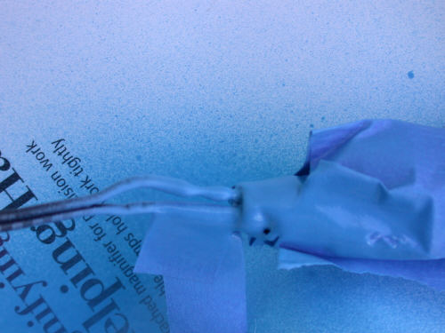
This is Performix "Plasti
Dip" spray on rubber coating. "Plasti Dip" covers the exposed wires. I've
never used it before, it's a spray on rubber coating that does the same
thing as electrical tape although you'll need several coats and some
patience to allow it to dry. |
First time I've tried this stuff. The switch itself is not waterproof. Not a big deal for me, but if you spend a lot of time in heavy rain maybe you can come up with a solution. Use at least a couple of coats to get good coverage |
|
The wire from the switch to the garage door opener is only about 1 foot long |
That is more than enough. |
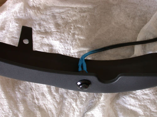
Slack is bundled up with a nylon tie. Oh, and this is from the "Read all directions first" manual, RUN THE WIRE FROM THE OPENER THROUGH THE BLACK PLASTIC SURROUND AND THEN TO THE SWITCH BEFORE SOLDERING!!! |
The micro sized garage door opener easily fits in the available gaps |
Garage door opener is tucked back behind a tubular bar |
|
Almost done |
Almost done |
Silver cover reinstalled |
Done! |
Black switch is stealthy
|
|
|
Could install another switch on the left if you need it |
Done! |
|
|