by Seacuke #1214
The
Voltmeter FAQ
compiled & edited by Kristian #562
Please read the Disclaimer before attempting any work in this FAQ.
There are so many ideas, we had to make a Separate FAQ.
Hodger VM Installation on a GS
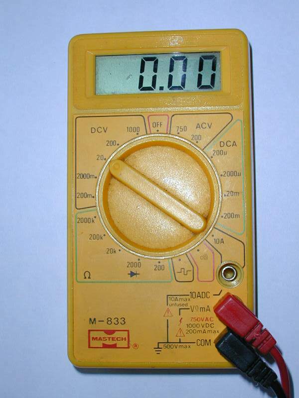
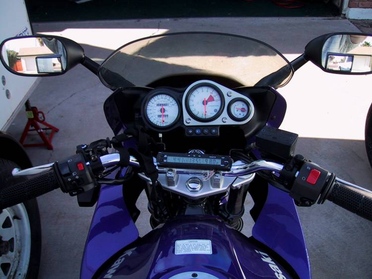
To check the Rectifier, for best results, make sure the bike is good and hot. Don't check it cold. Start the bike, rev it up to about 3-4K rpm and check the voltage at which the battery is being charged. You will need a Voltmeter (VOM), with one probe placed on each of the battery terminals. The Photo shows a setting at a minimum sensitivity at 20V which is a bit too high for the range you want to measure. The next one down is 2000 mV or 2V which is the one to choose. If you're not sure, START high, then go down, so you don't blow the Voltmeter. Refer the Voltage Rectifier FAQ.
Make sure you know the accuracy of your VOM when you buy it. That doesn't mean you have to get an expensive one! As an example some meters in the 25$ range have +-2% +- 2 digits accuracy, meaning that a 15.0 Volt reading could be anything from 14.5V to 15.5V. Others in the same price range may have +-0.5% and plus minus one digit accuracy which would give you a actual voltage of about 14.8V to 15.2V. Another factor is that only some meters from 100$ and up show "True RMS", others assume that DC is DC and all AC is perfect sine wave. RakaD.
Aftermarket Voltmeter in the Clock Space on the Classic
Werner #547
19-Mar-02
If you can, or want to, live without your timepiece (clock) and opt for a
Voltmeter (VM) this is what you do:
You buy a HASTINGS TA 1109 Volt Meter, because this model fits exactly into the cup holding your clock (650 Classic; I don't know about the GS - NOTE: This is your Temp Gauge location in Pre-97 Classic F's. Advise you keep the Temp Gauge and put a VM Elsewhere - Ed.).
Removal of clock:
Disconnect ground strap of battery.
Unscrew bolts holding fairing to tank on both sides, and lower fairing on left only. Unscrew the two Philips Head screws holding fairing to console. Do not touch flasher wires, but support sagging fairing with a wire on handlebars to take strain of flasher wire.
Unscrew nut holding clock with 6mm wrench. Lift out clock partly, to see wiring set-up. Pull apart four-prong plug and single wire plug. Lift out clock with wiring harness.
Take off O-ring from clock, and put it on VM. It will fit perfectly.
Pull off bushing and rubber grommet from mounting hole of clock. Keep for future use, if any.
Installation of VM:
Make a dry run, and see where everything will end up.
You will note that the two threaded metal studs of the VM are a bit short to hold the bracket supplied by the manufacturer. Find a piece of non-conductive circuit board, and, using the metal bracket for a template, drill the two holes for the studs. Make another dry run.
Before installation you have to do the wiring. You have three choices: (a) You can pull a separate wire from the VM directly to the battery. But then you must install a switch somewhere to turn it on or off manually. (b) You can use the red and white wire of the clock as a power source, but again you have to install a separate switch. (c) I chose to use the grey and yellow wire of the clock. This is the wire that powers the light in the clock. The advantage is that it is controlled by the ignition switch. The disadvantage is that since it goes through so many gadgets, there is a voltage drop of about 1+ volts.
Cutting the wires: You cannot get into the clock. I tried, but broke it. So cut the wires about 1" before they enter the housing, in case you want to reverse the operation later on, then you just have to solder the wires together. I used the brown wire, which goes to minus pole of VM, grey and yellow goes to plus pole. Ignore black, which was fast forward for clock. I soldered crescent lugs on ends of wires, then connected the wires to the threaded studs of the VM, to which I also connected the enclosed light of the VM. Test the assembled unit with a multimeter.
Feed wires into cup, followed by VM. Check on the bottom where wires emerge, adjust. Push down, and slip non-conducting bracket over studs, and tighten the two 8mm nuts (supplied) gently.
Connect the modified four-prong plug (only two poles are active) to its female part, and the lone wire from the fast forward switch, just to get it out of the way. Test installed unit with multimeter.
Connect battery, turn ignition key, and read about 11.5 Volts on the VM (there is a heavy load on the circuit with all the lights on).
Start motor and watch your work of art in action. For those of you who prefer clocks, eat your hearts out!!!)
Hodger VM Installation on a GS
by Seacuke #1214
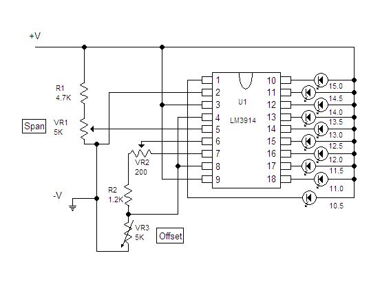
Above is the schematic for a simple voltmeter that could be
used to monitor the voltage on an F650. I borrowed heavily from Forrest
Cook, whose excellent circuit can be found here. In fact, the only
thing I really changed from his circuit is to remove most of the bells and
whistles from it.
The cost of all the parts I used to create this
circuit follow:
| LM3914 IC | $2.25 |
| 3 Yellow LEDs (5mm) | 3 x $0.19 |
| 3 Red LEDs (5mm) | 3 x $0.19 |
| 4 Green LEDs (5mm) | 4 x $0.19 |
| Potentiometer, 200 Ohm | $1.15 |
| Potentiometer, 5K Ohm | 2 x $.59 |
| Resistor 4.7k | $.10 |
| Resistor 1.2k | $.10 |
| IC Socket, 18 pin | $1.49 |
| 1" x 1" & 4" x .5" PC Board | ~ $1.00 |
| Total Cost | $9.17 |
The
output of this voltmeter is a bar of LEDs, each LED representing 1/2 a volt,
with the entire scale ranging from 10.5 volts to 15.0 volts.
Here's a
picture of the whole unit, with a pen in the foreground to show the size.

In the prototype I built, I separated the "brain" from the display of the unit, leaving me with maximum flexibility in terms of mounting options. I would imagine I'll end up sticking the display along the upper edge of the console, and Velcro the brain somewhere on the inside of the plastic headlight holder.
Also in the prototype I built, I used round 5mm diodes. This makes for a very large display, because of the way that standard PC board holes are laid out. For future units, I will use flat LEDs and be able to shrink the display from about 3 inches down to about 1 inch long.
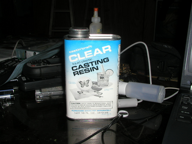
I also encased the display in plastic resin, rendering it waterproof and pretty much shockproof.
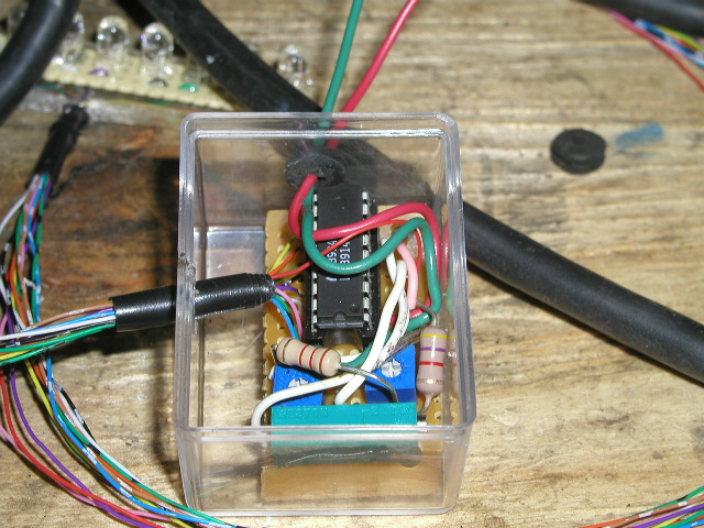
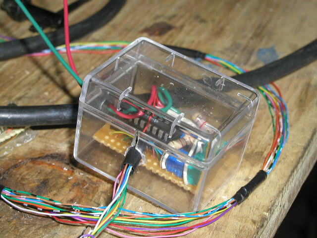
I found a small plastic box to encase the brain in, and will eventually tape this closed with electrical tape rendering it waterproof. (The wires have been sealed with silicone to ensure no water leakage through their ports).
Theoretically I could seal the brain in the same resin as I encased the display, but as you'll see, there needs to be adjustments made to the potentiometers after the unit is first installed (most likely). It is a good idea to keep them at least somewhat accessible.
The Adjustments
There are three adjustments that need to be made in order to have this voltmeter give accurate readings.
The first adjustment is to obtain 1.2 volts between U1's pins 7 & 4. I'm trying to remember why, but it has something to do with the LM3914's scaling or something. Do this by applying 12 volts (or so) to the circuit and adjusting VR2 until the 1.2 volt level is read.
Before making either of the next two adjustments, center VR1 and VR3.
The second adjustment requires applying 10.5 volts to the circuit and adjusting VR3 until the first LED just comes on.
Finally, apply 15.0 volts to the circuit and adjust VR1 until the top LED just comes on (all LEDs should be lit).
Alternative Lighting
If you wish to have a single LED on at a given time instead of the bar graph, tie pin 9 of the LM3914 to ground instead of hot. This causes the 3914 to just light the one corresponding LED to the voltage that's being read.
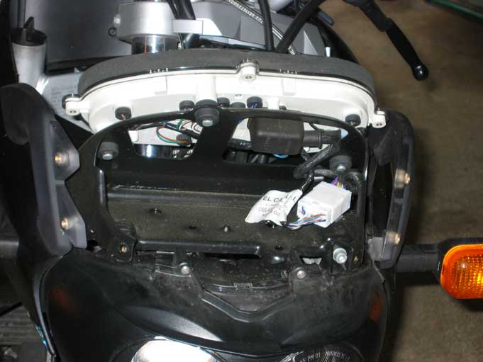
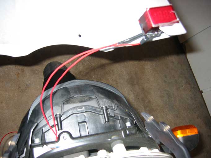
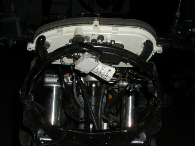
Installing the Hodger Volt Meter
I took apart the plastic 'head' of the bike, which encases the headlight as well as the console. I decided to use one of the little bulbs that lights the back of the console as a place to read voltage from.
The left-most of these lights was in a convenient location, so I decided to use it as a donor.
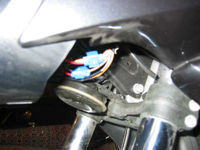
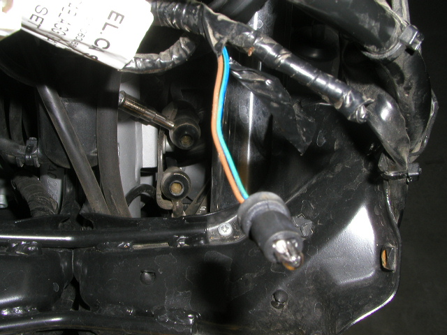
After attaching and bee-capping the wires, I stuck some Velcro on the
frame of the 'head' and the brain of my voltmeter. After some
poking and pulling, I decided to use a zip-tie to secure the voltmeter to the
frame in addition to the Velcro.
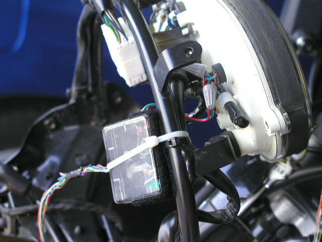
Here's
the Brain, attached.
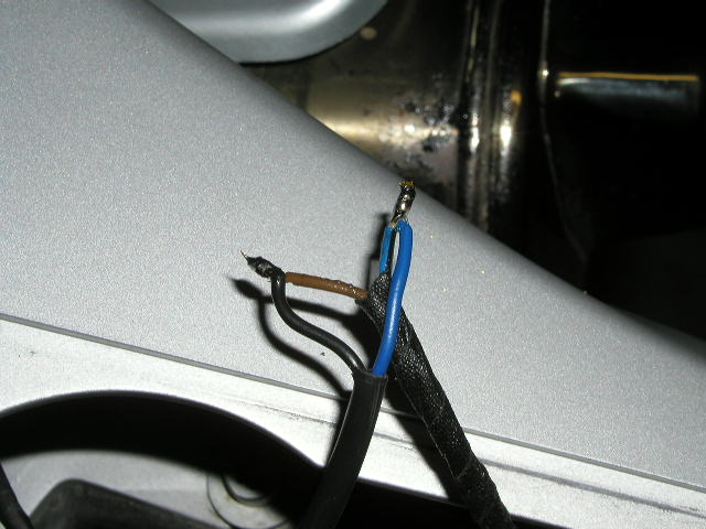
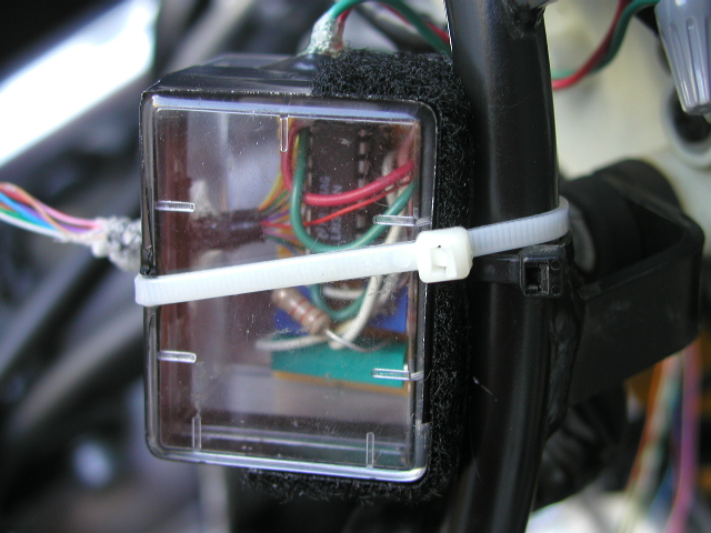
Close-up of the
Brain.
Close-up of the
Wiring.
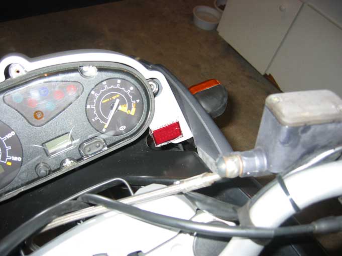
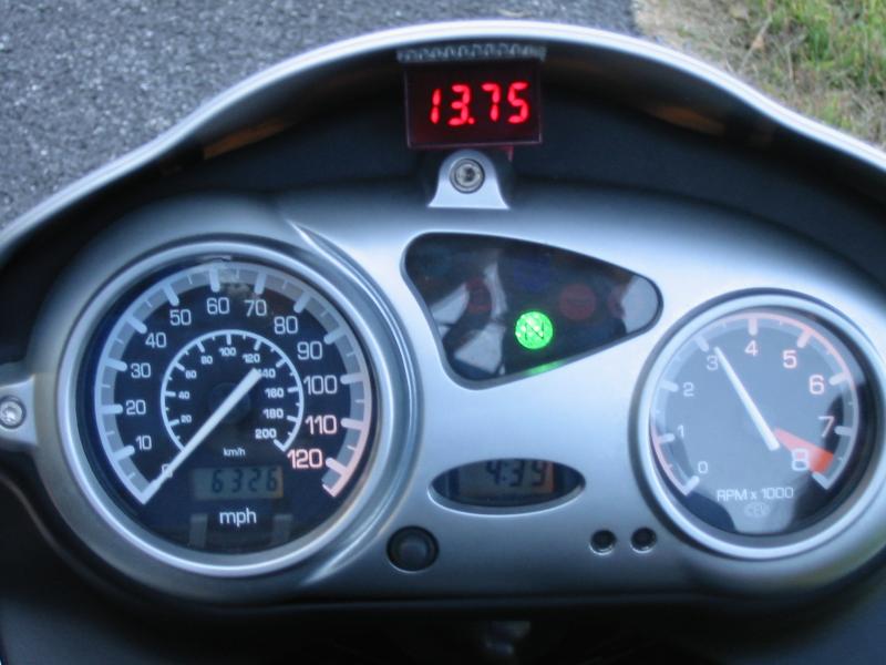
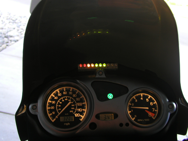
I decided on a left-to-right orientation on the display, and to mount it on top of the console. No real reason for picking this spot, I just figured it would look good there.
Here's some shots of the end result. The voltmeter reads
from 10.5 volts to 15.0 volts. Each diode on the display represents 1/2 a volt
(more or less).
Motor running, idle with radiator fan on:
between 13.5 and
14.0 volts.
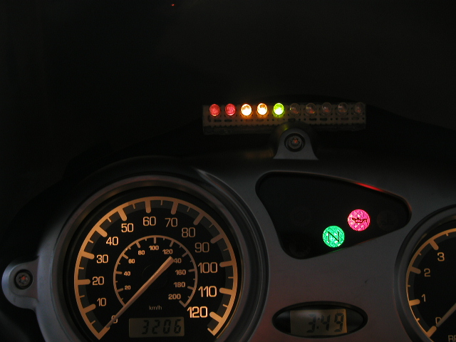
Just killed the engine:
between 12.5 and
13.0 volts.
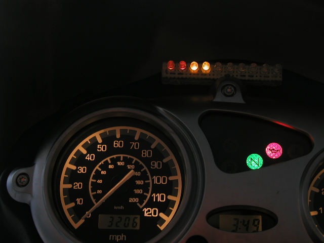
A few minutes later, the voltage drifting downward:
between 12 and
12.5 volts.
Installation went well, and I'm pretty happy with the end product. The installation page gives some hint of how it looks while operating. Seems like my bike is putting out around 13.5 volts when it's warming up, and after warm it puts out 14.0 volts (with no accessories installed). I ain't saying that mine is the best, or even a good idea for a voltmeter. I just like it because for some reason I really geek out when I see a bunch of diodes. The diodes I used aren't particularly bright, in fact if you're not looking straight DOWN on them, they're not bright at all. Why didn't I use a bar graph? No reason. In fact if I could find one that's 3 colors I would certainly use it - all the ones I could find are a single color and I really get geeked when I see multiple colored diodes. (10.5-11.0 are red, 11.5-12.0 are yellow, 12.5-14.0 are green, 14.5 is yellow, and 15.0 is red.) I did see your 3-diode circuit, and it does look nice and simple. Problem for me, giving away my lack of skills, I've never had any luck with 2N2222 transistors. I don't know why, I just have never, ever been able to get one to do what I wanted it to do.
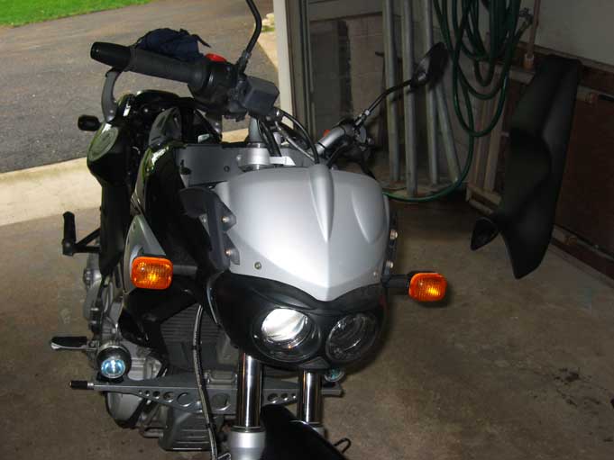
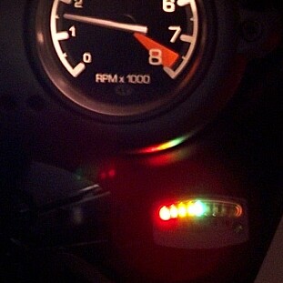
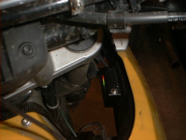 Here's a pic of my mount for the Hodger Voltmeter by
Seacuke. It should be noted that it's waterproof- if it wasn't this would
probably be a bad mounting point. I was trying to keep the lights out of my
field of vision since it isn't something I'll be staring at all of the time.
Mike
Here's a pic of my mount for the Hodger Voltmeter by
Seacuke. It should be noted that it's waterproof- if it wasn't this would
probably be a bad mounting point. I was trying to keep the lights out of my
field of vision since it isn't something I'll be staring at all of the time.
Mike
Regarding leaving the VM "on" all the time, the voltmeter circuit itself uses some minimal amount of power as well. So you would probably have less time than just if it was a series of LEDs that were lit. Flash or someone warned me about the bright light syndrome when I initially designed the Hodger VM as well. I rigged an on/off switch on mine, and when I forget to turn it off at night it is very distracting. I would highly recommend either an on/off switch, or some other way to reduce the brightness of the voltmeter at night. (My subsequent VMs have a switch to move them between 'dot' and 'bar' mode, where 'dot' mode only lights the one LED that corresponds to the current voltage being read.)
Feedback:
I wouldn't leave WIRE NUTS in a permanent installation of anything on a motorcycle. Solder and heat shrink for a permanent connection. If it is something you may NEED to disassemble later (like to remove the fairing)... use a connector like Molex or summat. Flash 412 (CO)
My highbeam idjit light is too bright for me at night so I put a damper on it. I'd be afraid that voltage thing would blind me if I looked at the dash at night, especially if it was in bar-graph mode. Maybe you should consider a photo-sensitive circuit in the common-cathode line. Why don't you use a bar-graph LED display, by the way? Do you REALLY need all those LEDs? Isn't the REAL question really a Three-Bears question, "Is the battery charge low, high or juuust right?" One red, one orange and one green LED would give you the information you need. How about THIS easier to build and easier to mount circuit? Flash #412 (CO).
Datel Volt Meter on a CS
by RideFast
| Parts List | |||
| Part | Price | Purchased From | |
| Datel Volt Meter [DMS-20PC-0-DCM] Shipping Tax |
$50.00 $6.00 $3.00 |
Datel | |
| Quick Switch Wire Crimps [5 pack] | $2.39 | ||
|
Total Cost: |
$61.39 |
Installation Notes:
Remove wind shield - 4 Torx bolts
Remove face over gauges - 3 Torx bolts
Remove front bracket, which is under windshield - 4 Torx bolts
Line up volt meter with bracket still in place taking care to notice how far the bolt comes through to get an accurate position for the unit
Drill the four corners of where you have marked the unit
Use jig saw to cut the plastic to fit the volt meter
Attach wires to back of volt meter before securing into place
Secure volt meter in the cut-out [double sided 3M tape, crazy glue, etc.]
Run wires behind gauges and down behind the headlights
***DETACH GROUND WIRE FROM BATTERY***
Find yellow wire [hot] and brown wire [ground] coming from the head light [low beam]
If necessary cut away electrical tape in order to free wire for movement
Strip the end of both wires coming from the volt meter
Use wire crimps to attach positive lead to yellow and negative lead to brown
Wrap crimps and wires with electrical tape
Reattach ground to battery
Test to make sure volt meter works
Position bracket and refasten - Position gauge face and refasten - Position windshield and refasten
Time: 2 hours
|
::Pictures |
|||||
 |
 |
 |
 |
 |
 |
| Windshield Removed | Bracket Removed | Cut Out | Make Sure it Fits | Running the Wires | Wires Crimped |
 |
 |
||||
I called the other day to find out about the LED Voltmeter they sell. I wanted to know if it's readable at night and how it mounts. The woman on the phone was very nice as always. She had a hard time finding it in her catalog {seems I have an old one) but when she did she said there is a note written here "not water proof will cause shorts in electrical system". The description in the paper catalog and online both say "completely waterproof". I then told her that I guess I didn't need any more information. Wamer #1021 CA
Those are nice displays, and a good size, though not cheap. But you do get what you pay for. One advantage of the LED (glowing red) display is that they tend to hold up to the sun better than the LCD displays. If you have to park in the hot sun, LCD's will usually cook to black eventually and be unreadable. Todd #389.
Datel Voltmeter
by Abe #963.
I have a
voltmeter installed on my bike - Pictures:
I originally mounted it below the Tach and it was fine. On the other hand IF you get creative you can mount it exactly where I have but will need to get a little creative. Since the 2 terminal screws are recessed once you make your wire/terminal connections you can cover the screws up with silicone putty etc and then glue the bottom to the panel. I have seen that done too and it works perfectly. I would do that, but didn't have access to the stuff and figured will do it a different day when I get my new windshield. www.datel.com. I am sure you are smart enough to figure the model you need. Comes in 2 variations - LCD ($20 cheaper) and the LED which I had on.
Installation was a piece of cake - find a switched live wire, connect into that and ground the other end. Seriously it took me all of 10 minutes! Dimensions on the voltmeter should be on the site - but it is pretty tiny & extremely accurate too - 2.5 samplings/second.
Custom Dynamics Voltmeter Installation
by Richard #230
http://www.customdynamics.com/LED_battery_gauge.htm
This weekend I mounted the LED voltmeter to my F650 Classic and found a good place to hook it up. Instead of connecting it to the headlight wires, I hooked it up to the "parking" light at the lower-right side of the headlight housing. I just pulled the bulb out of the headlight, soldered the ends of the meter's wires to the prongs on the bulb socket, stuck the female connections back on and pushed the bulb and socket back into the headlight shell. I then ran the wires up toward the handlebars and installed the voltmeter against the brake reservoir. I placed a piece of stick-on Velcro on the reservoir, so that its top was just below the reservoir lid. I then stuck the other piece of Velcro to the back of meter. The meter is mounted on the reservoir and I can now peel it off to add brake fluid. I ran the meter wire along the wires between the grip and the front cowl and zip tied them with the bike's other wires to keep things neat. This is much easier to do than messing with the headlight wires and if you make a mistake, you can do much less damage. Richard #230: 1997 Funduro, 2002 R1150R, 2002 Yamaha YZ1, 1993 Honda CB750 - Pacifica, CA, USA
Kuryakyn
Voltmeter Installation
by Richard #230
I finally received my Daring Kuryakyn Products (www.kuryakyn.com) "Universal LED Battery Gauge # 4219 (part number 604219)" voltmeter last night. The total cost to my door was $34.30. The voltmeter is housed in a small, very light chrome plastic case. It is 45 mm long, 25 mm tall and 12 mm thick. It has two wires about 12 inches long that have no connectors attached. It has 9 LEDs with an automatic "day/night" brightness control. The gauge is calibrated in 1/2 volt increments from 8-16 volts. Green LEDs for 12.5 to 14.5 volts, yellow LEDs for voltage above or below those values and extreme high or low values result in flashing red lights.
Frankly, the device doesn't look too weather-tight to me, as it has a big hole in the back where the wires come out. The instructions claim a 30 minute installation time, so it should take me 60 minutes. My plan is to hook it up to my new Ninjatte this weekend, as it has a nearby accessory power access just under the front fairing. I'll report back next week, if I haven't burned down my garage (I'm not too good with electrical stuff).
On the Kuryakyn meter all of the lights light up when it first comes on, then all of the lights to the left of the highest voltage reading light up. The top of the case is curved and there are imprints under the LEDs that mark their voltage. It is quite bright and gets even brighter in the sun. What I thought was a hole in the back of the meter (under pool lighting) was really sealed with a clear sealant. My only problem was that the spare accessory connectors that I hooked the meter to were not switched by the ignition circuit and resulted in the meter being on all of the time (it made a great garage night-light). I then realized that a few days of this would drain my battery and installed an in-line on-off switch to turn it off. Why didn't I just find a wire that was switched by the ignition? Because I had already cut the wires too short and couldn't reach the headlight wires. Now you know why I don't give electrical advice. I have a couple of comments about the Kuryakyn voltmeter after having used it for a day:
The voltmeter acts like a battery tester when you first start the engine. If the battery was bad, the voltage would drop below 10 volts, when the starter is engaged and the red LEDs would come on and you would know that it was time to look for a new battery. When I first turn the ignition on the meter reads 12 volts. When I hit the starter button, the voltage drops to about 11 volts (yellow LEDs), under the load of the starter. Then when the engine starts, it rises to 14 volts (2 green LEDs lit), where it stays until you shut the engine off. Even when the engine is off, the meter reads 14 volts. After a few hours with the meter connected, the voltage falls to 12 volts (keeping in mind that this is only an approximate value - typically a fully charged battery would show 12.6 volts).
I do not recommend that the meter be installed in your line of sight. The LEDs are very bright and can be distracting even in the daytime - to say nothing of what they look like at night. I would prefer the lights to be only half as bright as they are. Other than that minor problem, I recommend the meter. I consider it to be a useful tool to keep you appraised of your bike's electrical system's condition and it should keep you from being stranded by a dead battery or bad voltage regulator/rectifier. My radio station engineer friend tells me that each LED uses about 20 ma, so the 5 lights that are lit when the ignition is off would use 100 ma per hour and would drain the battery of about 1 amp/hour every 10 hours. The bike that I have it hooked up to only has a 6 amp/hour rated battery, so if I left the meter on I would be push starting after about 2 days.
Feedback
Installed my Kuryakyn LED battery gage today. Seems to work great, plus adds some color to my dash. You said yours had an open hole where the wires go in? Mine had clear hard sealant sealing wire hole. Unit seems to be water tight. Tapped into my headlight wiring to get switched power, made for very short wire run to voltage gage. Not the best picture but here is picture of Customdynamics.comKuryakyn Led voltage gauge installed on my F650GS. y2kcorvette
I received my Kuryakyn volt meter last week and installed it yesterday. Hooked it up to the heated handgrip switch. It immediately light up the left half of LED's. Put bike on battery charger over night. Same LED's light up after an overnight charge. Tonight I accessed the battery and saw it was low on water. Topped it up with distilled water and put back on Battery Tender. Hopefully tomorrow it will be fully charged and HOLD a full charge. If not I guess my battery's toast with less than one year and only 8000 miles on the bike. Does BMW warranty it's batteries for one full year? I wouldn't worry about the drain from a few LEDs over a few days. It would take a very long time for them to kill your battery. LEDs consume very little power- my scientific proof comes from a button I got on St Paddy's that was still blinking a few days later on a small watch battery. Anyone have non-alcoholic evidence against my findings? savant
I ordered the
Voltmeter from Custom Dynamics yesterday. It is 29.95 with a 5% discount til the
end of month. They told me it was the Kuryakyn. The price was 10 $ cheaper than
I had seen the chrome model at other sites. '01 F650GSA. Memphis, TN. county
I found this really cool meter sold by a company supplying aftermarket things for Honda Gold Wings. http://www.firecreekacc.com/digital_instruments.htm. I believe this would fit directly in where the clock goes. I may have to re-think this thing about keeping the clock. Another option is have a GPS which I want, one with a voltmeter built in (as per Mark 403), but keeping it on the bike all the time is not an option. It has an auto light sensor that reduces brightness in low light and when the voltage drops below 12 it flashes. I called to ask price and dimensions. They sell for 90.00 dollars and are 2 5/16 inches deep and need a hole 2 1/16 inches with the outside diameter of the basal (?) being also 2 5/16 inches I may call this company again and see if I can find out who makes them because I would like the additional features without the round housing. Wamer #1021
So, I was looking on the WEB, and found someone who has made a number of bike-related gadgets, including the 3-LED thingy. Not sure where that leaves me, but here is the web site FYI. http://www.mindspring.com/~wayne.orwig/utils.html. Cheers, Scott.
You might also check out. http://www.electricalconnection.com/meters_indicators/bm.htm. RogerN #827-C. Illinois
Radio Shack has a http://www.radioshack.com Alternator and Battery Tester for US$6. Me, I just use the voltmeter in my GPS. Flash #412 (CO)
Another
trick gadget: BSM. Motorcycle "battery status monitor." A single large LED that
changes colors based on voltage. Made to be easily dash mounted (drill one 14mm
hole and pop it in). Only see one UK supplier: price 10 pounds. Don't know about
shipping to the US.
As the voltage across the battery changes the LED colour changes:
RED More than 15V - Over charging or charge system high voltage, check
regulator!
GREEN 14V to 15V - Battery on charge.
YELLOW 13V to 13.5V - Heavy electrical load, engine running.
ORANGE 12.5V to 13V - Fully charged, engine not running.
RED Less than 12V - Battery low, or loaded with engine not running
http://www.nanocontrols.co.uk/auto/bsm.gif,
http://www.aoservices.co.uk/. Mason
#631 - 97ST in PA
The BSM unit available from Sterling. http://www.sterlingmotorworks.com/inc/pdetail?v=1&pid=455
The Datel units are tiny (but pricey). US$50. Datel Digital Panel Meter DMS 20PC series. Runaway #1259 (CO)
This looks kind of neat and the price isn't too bad: http://www.customdynamics.com/LED_battery_gauge.htm
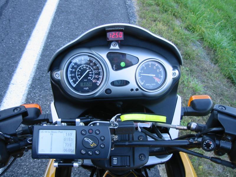
 I
have a gadget that I've installed in my car and two of the bikes that provides
much the same thing (Battery Indicator) plus a few other features. It's a
3-panel LCD display that provides a clock, timer, digital voltage meter, and two
ambient-temperature sensors (one inside the unit, another on a remote cable). It
also has high/medium/low status lights for battery voltage, a low-voltage
audible alarm, and an ice alert when the temperature of the remote sensor is in
the range where ice might form (not too much activity on this one here in
Arizona). We have one on the 650CS but I don't have a picture of it; you can see
it in the following image of my Kawi 750, mounted on the handlebar clamps: Very
handy gadget, easy to install and a great deal of utility for $26 (from AllCycle
in Arizona). DesertRider
I
have a gadget that I've installed in my car and two of the bikes that provides
much the same thing (Battery Indicator) plus a few other features. It's a
3-panel LCD display that provides a clock, timer, digital voltage meter, and two
ambient-temperature sensors (one inside the unit, another on a remote cable). It
also has high/medium/low status lights for battery voltage, a low-voltage
audible alarm, and an ice alert when the temperature of the remote sensor is in
the range where ice might form (not too much activity on this one here in
Arizona). We have one on the 650CS but I don't have a picture of it; you can see
it in the following image of my Kawi 750, mounted on the handlebar clamps: Very
handy gadget, easy to install and a great deal of utility for $26 (from AllCycle
in Arizona). DesertRider
Next.
Voltmeter Feedback:
A most useful and cheap gadget is a voltmeter. Then you can always monitor the voltage when riding. Haakon#626
Why for you want to install a voltmeter? If your battery goes bad a voltmeter will not prevent it. There are plenty of warning signs when its time to replace the battery. A voltmeter is just a gadget to go wrong or screw something else up when you install it. My brother had Honda install a theft system in his car in 93 despite my warnings in 1993. Now he's having all kinds of electrical problems. echo, F650GS Dakar, Camden, New Jersey.
A voltmeter is one of the simplest and most useful electronic instruments to use on any auto. Al from Oregon.
I am kind of guy that likes to have some control over things, so therefore it would be a good thing for me to install a voltmeter, so that I can see that everything is Ok or not. It is also a good thing to have for checking if the VR is bad or not. Since I didn't have one installed and since I didn't bring my multimeter with me, I had to buy a new multimeter to check it. Finding a battery in your home country where you know what store should have one and you speak the language is easy, in another country, where you don't speak the language is a different matter. I am going to go the local BMW shop in town and order me a VR, in case it's bad. Regards, Spakur #1117, Icelander in Malmö, Sweden, 1995 Classic Red F650 with 65.000+ KM