by Mike Galmukoff, Advrider.
The Aftermarket GS Lights FAQ
compiled & edited by Kristian #562
Updated by Scott, ID #1244
Please read the Disclaimer before
attempting any work in this FAQ.
This page is for Photos and
Installation Write-ups of Aftermarket Head Lights, Turn Signals, Brake Lights installed specifically
on the GS.
Due to the nature of Lights, all Opinions and most installation
Tips are included in the Classic
Aftermarket Lights FAQ.
For
General OEM Information - Headlights,
OEM Bulb Installation Tips, Headlight Problems
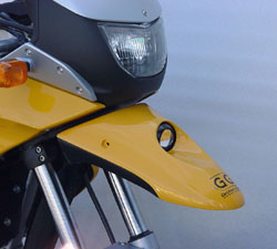
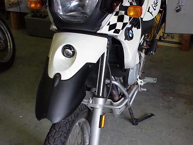
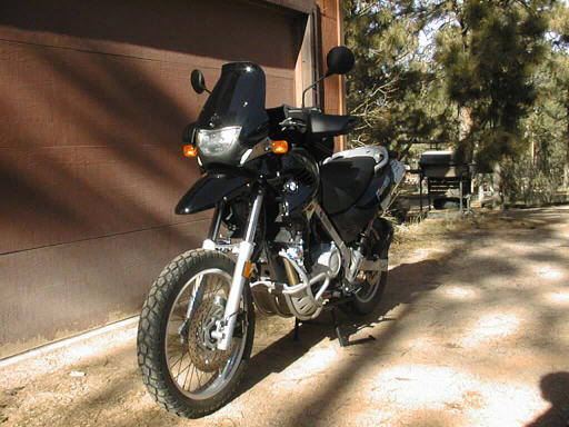
G&G Technik's Light In The Fender
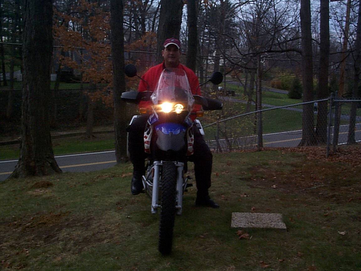
by Mike Galmukoff, Advrider.
Got this trick fender from Ridewest in Seattle. When we pulled it from the box
at the dealer we found it was a bit warped. Probably due to a "hot lay-up". The
fender is fiberglass. Ridewest was real cool about and gave us a real sweet deal
on it. I took it home and did the re-shape, primed and painted it. It lights of
the trail nicely.
Q. How much for the fender/light setup?
A. From G&G Direct it is 495 SFr. El Lo
Q. What is the brand name of the thing?
A. Contact:
http://eurotechmotorsports.com in CA. It is made by the
Swiss Company G&G. I purchased one and
it is easy to install, looks good and works well.
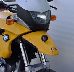
Q. What sort of lamp is that?
A. No name on the lamp. Real thick magnifying lens.
Q. Is it a driving beam or a fog beam? Looks
to me like some sort of fog pattern beam. Who makes the lamp? Hella, PIAA,
someone else?
A.
It is a
HELLA OPTILUX 1100. These lamps were produced in Europe about 1990. They
were made for a company which resided in Hamburg/Germany. Nowadays they are sold
only in USA, not in Europe. The bulb is 12V 55W H3. Robert #1071
Q. What's the throw of the lamp?
A. Unknown.
Q. Is it only good for those night time
assaults on the trails, or does it have enough throw to use on the highway in
the dark?
A. Good enough for full time use.
Feedback:
 I have added the additional headlight made by G&G. I am very satisfied with
it. The great advantage over others is that it does move with the steering.
Robert. robert61
I have added the additional headlight made by G&G. I am very satisfied with
it. The great advantage over others is that it does move with the steering.
Robert. robert61 Unkown.
Hella Lights
Jason #1027
I don't want to sound like a broken record or a salesman but I honestly endorse HELLA driving lights. I've used them on all of my vehicles without a single failure due to manufacturing. They are extremely resilient and I just can't find anything about the PIAAs, aside from bragging rights, that is better than comparable model Hellas. It is irritating to see someone drop 250 quid on a set of lights that, IMHO, just aren't worth it.

Here's a minor testimony to the FF50's: I just came back from a little tour of
the NW. 3800 miles later I find myself on highway 90 between Spokane and
Missoula in the middle of the night and it's raining. Even though I was going
slower than most other drivers wanted to go, they would not pass me - but pull
in next to me to let me light the canyon. No, I wasn't being a prick and leaving
my lights on when they did pass. I just happened to be the brightest thing in
the canyon. Yes, it was kind of a strange experience, but if you spend twice as
much on a "better" lamp then I think you're strange :-)
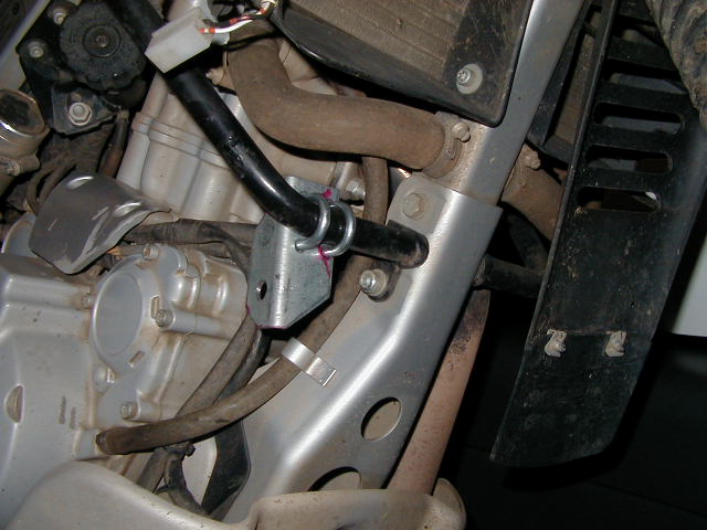
Is anyone using the Martin Fabrication light bar WITH the BMW tubular engine guard? It looks like the two may conflict that they will fight for the same mounting locations. But I thought I read somewhere that they WILL work together. I would like to add some lights to the Dakar, and this looks like a nice way to do it. But will it work with my guard. Anybody know for sure? Also: Have you every dropped the bike with a Martin mount? Do the lights survive? DakotaDakar#1198
I had the same question about the Martin bars. I have the BMW engine guards on my F650GS. So I sent an e-mail and here is the response: "The light bar mounts to the 4 fasteners that hold on the plastic radiator fins. This is located on the down tube of the frame. I think the crash bars mount lower. Let me know if I am wrong. Thanks, Bryan Martin" So I think I may give it a try. Sven #984.
Yes, that would work. The radiator fin bolts are above the guard bolts on the down tube. Should not conflict at all, if this is correct. And now that this is pointed out, I can see in the photo that this is where they are mounting. DakotaDakar#1198
I have these light bars on my GS: Martin Light Bar and can highly recommend them since even in tip overs the lights were scratch free! I have the BMW engine guards mounted on my bike. The 650 GS has a 400 watt alternator (the older 650 is 280). But even with 400, you will most probably drain your battery with those lights. I have the 1000x and they seem more than ample! Even with these lights in stop and go traffic I need to turn them off. I am planning on adding a volt meter from these Datel which should help me keep an eye on the voltage at all times. I have seen it mounted on a friend's bike and is much better than the one from 'stitch. I have the BMW engine guards and the bars from Martin. They are really well made and they fit onto your frame right around the radiator. Very close fit but perfect. Although expensive, they do work! Dumped by bike twice on a trail and not a scratch on the lights! Plus, what I like about the mounting position - * not very high up - avoids blinding on coming traffic and blinkers not being visible to them (important to me in urban areas) * not so low that water crossings submerges them ( I have been thru about 2 feet of water and they were fine). I have the BMW engine guards and the bars from Martin. They are really well made and they fit onto your frame right around the radiator. Very close fit but perfect. Although expensive, they do work! Dumped by bike twice on a trail and not a scratch on the lights! Plus, what I like about the mounting position - * not very high up - avoids blinding on coming traffic and blinkers not being visible to them (important to me in urban areas) * not so low that water crossings submerges them ( I have been thru about 2 feet of water and they were fine) * protected in case of tip overs. I have the PIAA 1000x's on the Martin light bar. I love it and can tell you that I have not had any problems with the lights even when it tipped over (in mud). I would recommend getting a volt meter to monitor your battery since these lights can definitely drain your battery in stop and go traffic. The PIAA's are on a separate switch, since in stop and go traffic they begin to discharge the battery pretty quick - which is why I got the volt meter! In the NYC area stop and go traffic/ lane splitting seem like a part of life I tend to use the PIAA's mainly out on the highway when I am cruising at highway speeds. Asterix, Advrider.
Since the bike only has a 280 Watt alternator and I also have heated grips and use heated clothing sometimes when it is really cold I opted for the Touratech dual headlight. You would figure that the standard light plus the grips and electrics are bad enough. Then to add another 110W worth of PIAA's will probably be cutting it real close. No mounting brackets, two 55 Watt H3 bulbs that you can swap out for 85's for low and high - puts out a bunch and really catches the Cagers eye when the highbeam is on during the day. Pattern is pretty good for the woods too. PhilSpace.
Thanks for the link on the Martin Light Bar. Without a closer shot, I can't see where it attaches. Do you have BMW engine guards? I do and this is the reason the RCU light bar won't work, and I need to determine if the Martin has the same attachment point. I suppose I could try to attach some PIAAs to the engine guards if need be. Sven

 Abe #963. Martin Bars.
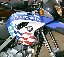 Marin Light Bar on Dakar.
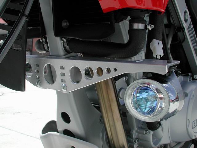
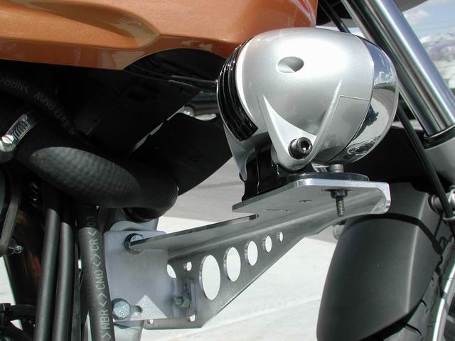
MicaTech Light Bar
Runaway #1259 (CO)
I've been shopping around for lightbars for a set of PIAA's or similar lights and found a small company on the adv board that makes a nice titanium lightbar for the big GS. It's priced reasonable for a titanium product ($109 as compared to around $150 for an aluminum Martin Fabs) and I asked them if they would consider producing one for the F650.
Here's their response:
"We understand that from year to year and model to model there are some variances which would require different designs for light bars on the 650. If you would be willing to organize a group purchase of 10 or more who would want a Micatech Titanium light bar designed for an '03 650GS (and same-design related models/years) then I'd be willing to build it and bear the design/prototype (s) costs."
So, here's my question: would anyone be interested in such a product (if pricing stayed comparable to their 1150 bars)? I guess I'll ask Prof about possibilities when he gets back (I saw the sharkfin etc and figured maybe this was also a product the CG'ers might have an interest in. I'm still pretty new to the CG and f650, so if I'm way off base here, let me know...it's something that looked good to me so I figured I'd give it a shot and see if there is any kind of initial response. Natalie
It's available now from http://www.micatech.net/products.htm. $135 plus shipping.
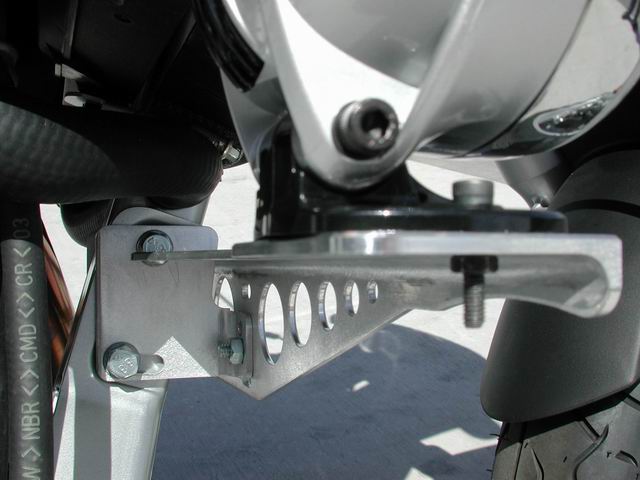
Some modifications to the bracket were made to allow installation with engine guards. The group buy offer will be announced on the CG homepage as soon as everything is completed.
I just received the first lightbar and I'm very impressed. The pictures don't do the product any justice, it is much stronger and more solid than it appears in the photos. I had expected a good product and I think it was well worth the wait-the lightbar is nicer than I had hoped yet and IMHO beats anything previously offered by other manufacturers. Feel free to e-mail me with questions and keep an eye on the homepage info section for the group buy announcement!


Additional Photos Belonging to Unknown:

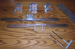
PIAA Light Mounts #2
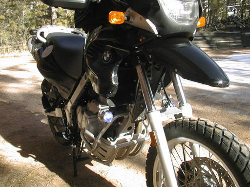
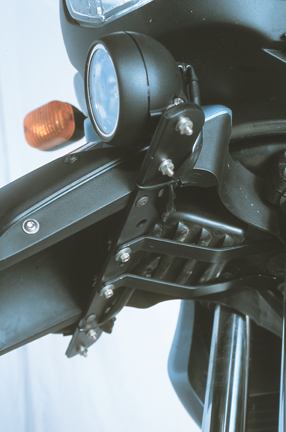
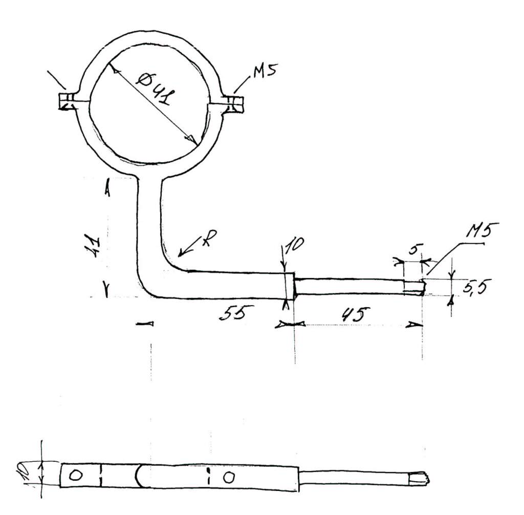
by Victor from Russia
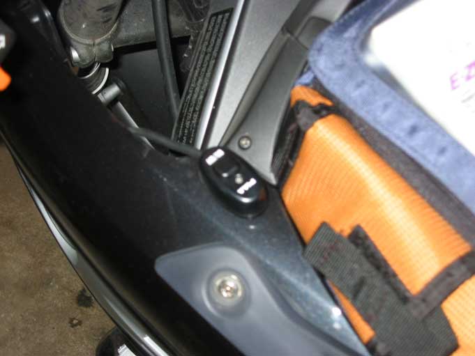
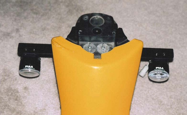
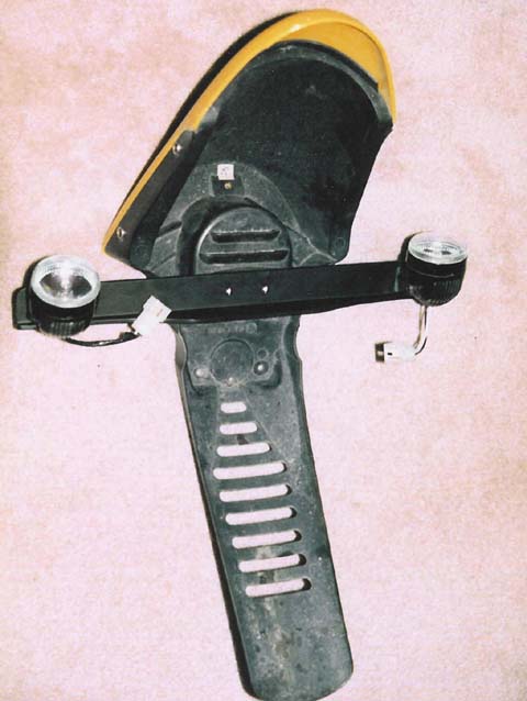
The mounts are steel, plated with a Chrome coating. Here is the Mount Setup Diagram.
What you see installed here is Aluminium. You will need to insert a small tube
into the light mount if you tighten it due to the plastic body.

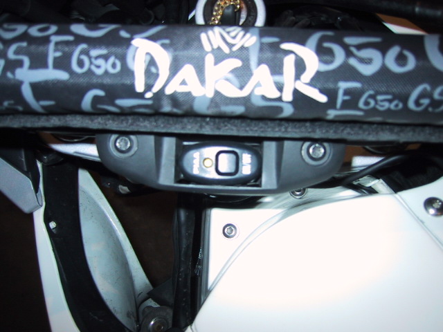

I put the On Off Switch into the existing slot for ABS switch.
PIAA Light
Mounts #3
Unknown

PIAA Light
Mounts #4
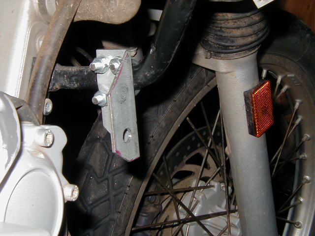
By RideFast
Loosen both bolts that secure the engine guard (13mm).
Attach the two brackets with feet facing out using supplied (longer) bolts. Reuse original washers and nuts.
Be careful NOT to OVER TIGHTEN, as the brackets can be bent
Attach front piece with supplied hardware.
Bolt PIAA's into light bar with supplied hardware.
Use LOCTITE on all bolts.
Time: 20 minutes
Wiring:
Disconnect ground wire from battery terminal.
Snake wires to lamps.
Attach positive lead to positive terminal.
Loosen + Terminal - snip + lead fastener on PIAA wire and slide over screw - tighten (much easier than removing entire thing).
Mount switch and connect to supplied plug already wired.
Connect lights via wired plugs - hide wires as you like.
Find hot wire to wire switch power (I used the tail light).
Reconnect ground wire with ground lead from PIAA's attached as well
(You may here a clicking noise when you reconnect the battery
this is normal and should not be a concern.)
Time: 2 hours
Note: I was going to have my dealer do this install, but when I called them they said the CS couldn't handle PIAA Lights and they would not do the install. I found this a bit absurd, as I have seen many 650GS (same battery) bikes with the PIAA's. The wiring was really easy and I saved 2 hrs worth of labor. I am also installing a Volt Meter to monitor the battery just to be safe.
Update 17.June.03: After having the lights installed for only a few weeks one of the bulbs burnt out. I called Automotive Accessories Connection, as they have the cheapest replacement bulbs I have found. They are great people, when I explained what happened they looked up my order, marked it as warranty and replaced the bulb for free...only charging me for shipping.


PIAA Light
Mounts #5
By Brendon
I am still finding it incredible that folks charge and other pay such outrageous prices for light bars. Outraged at the prices I went to a local welding shop and had them cut me a 18" piece of angle aluminum, with some slight details (COST $10.00). I drilled 4 holes to mount the PIAA lights I had and 2 holes to mount it to the bike. I over drilled the holes just slightly. I got it powder coated flat black (COST $5.00). I mounted it under the fender through the vented part where the horn is with some stainless bolts, fender washers and nylock nuts (COST $3.00). It looks and performs great. Total cost was under $20.00 and about 1/2 hour of my time. I made one a while back using a flat 5/16 aluminum bar (COST $0.56 from the scrap yard) but found that the bar transferred too much vibration. The angled aluminum solved the problem. I like that it turns side-to-side with the bars. I ride a lot at night and it has been a life saver. PIAA Light
Mounts #6
The Wolverine gave me a set of PIAAs that she pulled off her International Scout a decade or more ago. I went down to Home Depot and bought a couple of galvanized brackets used for attaching a wooden 4x4 to something or other for about $2.50 apiece. I cut some of the tabs off the brackets and drilled some holes in them. Using a grinder, I radiused the ends to match the radii of the PIAA brackets. I broke the other corners and edges with a file and then painted them with black semi-gloss engine enamel followed (after appropriate drying time) by treatment with a heat gun to harden the paint. Here is how I
mounted driving lights "Rallye Lamps" on my '01 GS. These lamps are not PIAA,
but give me light out to about 50'. If I lose my main lamp I could drive by
them. It is not like driving in the day, but good enough to get by. I have had
these lamps on since April. I did a little re-enforcing of the plastic with
galvanized metal on the inside of the headlamp area. I have been on a rides
through the woods and back roads with no ill effects. I get the light I wanted
in the evening. Disclaimer: This is for reference only. I do not
warranty any comments here. So if you are not competent with tools or fail to be
mechanically inclined -- HIRE SOMEONE. My grandfather was a carpenter and
instructed me to measure twice and measure twice more then cut. The plastic on
this bike is costly, so think carefully, think carefully, measure and proceed at
your own risk. Here is a picture of the box the lamps came
in.
Double click the picture to view the kit
content list,
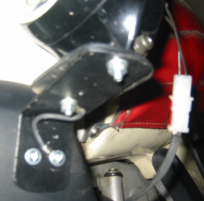
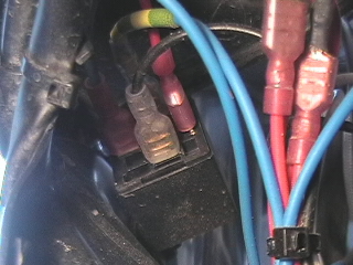
On Off Switch:
I placed the relay up under the instrument
panel. The picture does not show the wiring because the relay is mounted with
the connections pointed upward. I had to drill a small hole for the nut & bolt
to pass through. The hole is drilled through the metal frame that supports the
headlamp and gauges. The relay is above the braided line in the picture.
The power for the lamps is run directly to
the battery as well as the ground. The fuses are secured next to the battery. It
would make sense to move the fuses back under the seat for easy access. An
afterthought and something to do later. The wiring should be covered with a
sheath to protect it against rubbing along the frame. In this case I use heat
shrink again.
Rallye Lamps #2
http://www.bmwofsaltlake.com/rcu/rcugscslightrack.htm
Feedback:
Q. RCU light bar & Engine Guard. Do they work
together?
I have a Bridgeport endmill in my garage and thought
of making my own mounts. However, The RCU is a very nicely made CNC unit that
would have taken me a long time to make something comparable. I like the idea of
keeping the lights lower to the ground. The lights I got were about the same
price ($50) but the mounting hardware looked more rigid on the Hellas. As for
the light bar, it was worth it to me to have a nice clean, finished looking
installation. I'm sure a couple of angle brackets would work fine (not so sure
about the tape though), but I would not have been happy with the finished
product. For the same reason I spent two hours soldering/shrink wrapping wire
connections and stringing wire into a professional looking wire loom for the
lights. Warren #1219, Pacifica, CA
I don't see what is so complicated. Get a couple of
these or these (sometimes they're on sale for $19.99) or even these. Then getcha
some angle brackets, if need be, to mount them. You can mount them anywhere you
can get screws in. For that matter, the projector beams come with double stick
tape. So you can just stick 'em on. ($100 for a light BAR?! I shake my head in
wonderment.) Flash by Ed #670. Updated by Gerry #951 Here are the photos (click to enlarge) of the
Touratech dual headlights on low beam and high beam. I drove with them at night
down a very dark road with no moon light and they needed adjustment from the
installation. The low beam was average and the high beam was excellent.
Installation: Currently
Touratech only has the instructions in German. Here is a translation.
Remove
the turn signals. Remove
the left and right faux gas tank pieces.
Touratech recommends that you remove the center plastic piece and disconnect
the battery. I did this but in retrospect I think you can safely skip this
step and save time. Remove
the windshield. Loosen
the two plastic Philips screws on top of the headlight housing. Pull
the headlight housing from the bike and disconnect the wires. Cut the
parking light bulb. Remember to leave enough wire to the parking light in case
you decide to reattach the original headlight. There are two crimp-on
connectors included in the kit. Attach the female plug crimp-on to the gray/black
wire and the male plug crimp-on to the brown wire of the parking light.
Remove
the headlight from the housing by unscrewing the three adjustment screws until
the balled end of the bolt pops out of the plastic anchors which then can be
removed from the housing. Remove
the rubber from around the headlight. Place
the rubber around the new headlight and headlight cover. Place
the white anchors on the new headlight adjustment screws and place the
headlights into the housing seeding the anchors and screwing the light into
place.* note: There is a metal plate that serves as an anchor for the
windshield that goes between the headlight and the housing. 12.
Attach the wires for the parking lights and then the driving lights. The
driving light wires are color coated with the wire to the plug. Just pull the
rubber back a little to see the wires (white: high beam, yellow: low beam,
brown: ground). (There are great details wiring instructions and a picture at
http://www.touratech-usa.com/instl/instl_040-1200.html ) Attach
the housing by putting the plastic screws in first (for those of you that
haven't had the pleasure to put these back in you will enjoy the poor thought
process of these and the pain in the @*% that they are to get back in). Try
using a 3/8” socket extension to push the tab from behind the headlight.
Replace
everything in the reverse order that you removed it. There
are two lights. The low beam is on the left and the high beam glows as a
parking light. When the high beam is activated it projects a good beam. If the
low beam would go out then you would still have the high beam to get you to a
parts store or home. See also
Touratech's Headlight Photos. I
just installed them today. They are MUCH BRIGHTER than the OEM headlights. Be
careful to make sure they are aimed properly; I'm considering dismantling and
doing the install again to get them dialled in properly. The adjusters aren't
that good. But they look very cool and the light they throw off is excellent.
Installation was easy, save for the part I just rambled about above. An
excellent improvement. Chris I
have this headlight setup and ride in the desert at night. It works great. For
the Dakar Touratech also added the Xenon external light which they put on the
R1150GS. I'm adding this as well to both of my F650 based bikes. If you do the
dual headlight conversion you won't be disappointed. Davidhpark, #711. by Gilles Gueveneux How I fixed a Xenon lights on my BMW F650GS First, note that it's not an easy job ! These
pictures where taken 1000 miles after installation. Every things seen O.K. So
far, so good. But If you do it, remember to inspect it every now and then. Premièrement : c'est pas un
travail facile !!!!!!!!!!!!!!!!!! Les photos ont été prises après 1600 km. Ce
type d'installation demande une inspection regulière. The bracket: 1/8" think steel plate in the
shape of the white line shown in the photo, 4 holes and much trial and error
bending it to match the motorbike. In red : rubber glued on the plate to protect
the plastic parts. 2 bolts : M5 X .8 X 35mm length.
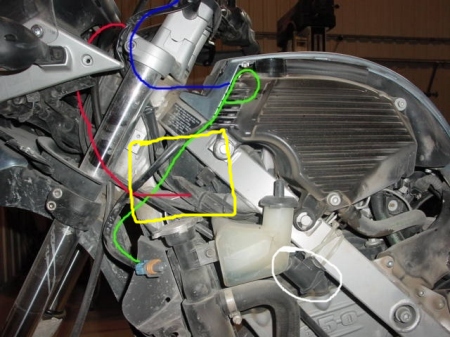
Red: High voltage ( 20K volts ) cable
between transformer (Yellow) and the lamp.
The transformer: First I had to cut some
aluminium parts from the original Touratech bracket to make it rectangular. Then
I used an old tube, cut to the length of the transformer and fixed it in place
with one bolt and a large washer. I fixed it to the air dock and used a small
tie wrap to hold the transformer level.
The last picture: You can see where the
transformer goes. Circled white is where I fix my lighter plug.
It's worth the time needed to install it. If you
find an easier way to do it, please contact me and I will update this page.
Comparison of TT Lighting systems
Sources: See
the Classic Aftermarket Lights FAQ
for Installation Tips & Troubleshooting.
Acerbis Turn Signals
There's a single Torx-30 bolt that holds the
signal to the body. Remove this bolt, it will no longer be needed. Cut the wires
that connect the turn signal to the wiring harness, leave as much of the wires
with the bike as possible. Actually, there is one on each side of the
compartment. One side is held in place by the Torx-30 bolt that holds the turn
signal, the other side is held in place by another Torx-30 bolt, washer, and
lock washer. Remove the bracket by first removing the turn signal, then
unscrewing the bottom Torx bolt. After removing the bracket, make sure and
return the Torx-30 bolt.
Just for the record, the Buell signal mod don't
require modifications of the bike itself, one of the things I'm trying to do
with any modifications I make is to be able to return the bike to "bone stock"
if I ever want to. Feedback on the Buell If I
understand it right, the Buell Y0503.9 and Y0504.9 are the right and left exact
replacements (not flexible) and the Y0503.k and Y0503.j are flexible, but not an
exact fit. The Touratech 040-0209 for twice the money and available only as a
four-pack require some drilling also. SScratch
You could use the
KTM flexible signals as used by Iceman on his
F650GS Super-Moto conversion. Next. Just this weekend,
I ordered a 4-pack set of replacement turn-signals from Touratech-USA for $50US.
My girlie-friend did in two of them ... p/n 040-0209. Ray Downes Chuckles has a set
on his bike and he says they work very well.....I got a set too, but haven't
made time to install. If it were me ( and I did) I'd go with the Touratech.
Thumper, Austin TX, 02 Dakar. The Touratech
signals are smaller than the stock BMW signals, but are visible in traffic -
they use the same bulb from memory. Over time and many kilometers/miles the
bouncy rubber will eventually wear out (budget for 50,000km), but if you are
going to do a bunch of off-roading they are certainly worth it...Lance, #1303,
'01 F650GS. Turn signals getting trashed? I tour Australian dirt roads
on my Dakar - 10,000 km since Sept. 2001. It's inevitable the bike gets dropped
and the turning lights hit and snap. Yamaha makes an almost identical light
fitting with a rubber neck on their 400cc trail bikes, perhaps others. They look
the same as OEM BMW - are more practical and don't smash when you have the
inevitable off.
by Andre Le Lievre
Wiring Aftermarket Head Lights into the GS Rear Tail Light Circuit?
by Haakon #626(Norway-F650GS) The
Problem: I've got these PIAA x1100 lights mounted up and the wiring harness
wants to have you splice into the high beam power cable so that (legally) the
lights are only on when the high beams are on. So I'm breaking the law, I want
them on or off when I want them on or off. But I also want them to turn off when
I turn the bike off. So, I'm thinking of instead of using the headlight circuit,
I'll use the tail light circuit to provide that +12v signal as to when the bike
is powered up. I've checked the FAQ and the wiring diagram for the '01 GS but
still can't figure out which wire is the tail light (vs. the brake light and
turn signals) in the harness that runs to the rear of the bike. Anyone know
which color it is?. The relay is tucked under the airbox and it's really easy to
get at the tail light harness back above the access to the gas tank. I didn't
know there was a 'running light' in the headlamp assembly, but I'm mostly afraid
to go poking around in there. Once I get the light project finished I'll try to
post a picture so everyone can judge how they like the PIAAs and the RCU light
bar. Kelly #1005. The
Solution:
Comments: Todd's
post is exactly what I did. If you want to also be able to control them with
the high beam switch when you want. Takes another switch, unless you want to
ditch the PIAA switch (wired for 'on'), and replace it with a 3-position
switch (high-off-low). on high, you'd control the PIAAs with the highbeam
selector, off is off, and low is always on (controlled by ignition). I will
probably go this route the next time I have the rear of my dash exposed. mark
#403 Next.
By Flash #412
Another Homemade Light Bar Installation:
I drilled holes and mounted the brackets to the plastic engine side covers below the gas tank with a couple of screws each. I soldered some ring terminals on the ends of a pair of pieces of wire an inch or so long to be used as safety restraints in the event that the brackets break from fatigue while I am riding. Hopefully I would notice the light dangling and rescue it if the brackets turn out not to be up to the job.
The brackets follow a line on the plastic that tilts them forward. This is a Good Thing since it means that the lights are tilted somewhat up when the bike is unladen. With a load, the back of the bike drops some which means the lights need to be tilted down so they don't shine up in the trees. If the brackets were level with the ground, I might not be able to get enough down-tilt to keep them where they need to be.
The angle brackets are splayed slightly OUT as attached to the bike. But the PIAA brackets have enlongated holes that allow enough left-right adjustment to get the lights pointed in the right direction.
I ran a healthy wire (via a fuse) from the battery to a relay TyWrapped to the frame that holds the fairing. The relay is activated by a three-position (center off) SPDT switch AND via a diode from my horn relay. The diode connection means that whenever I beep the horn, the lights will be illuminated as long as the horns are blaring (if they aren't already on). (The diode keeps the fact that the lights are on from beeping the horn.) One leg of the switch is connected to the parking light circuit. (I have a Euro lightswitch and can run only the parking lights if I want.) When the switch is in that position, whenever the ignition is on and any lights at all are on, the auxillary lights STAY on. The other switch position is wired to the high beam signal. This means that whenever the highbeams are on, whether flashed or on steady, the auxillary lights will illuminate, but go off when on low beam (or parking light only, or not lights at all).
The light brackets were attached to the angle brackets and the angle brackets to the bike side covers with 4mm screws and hardware. In the photos, the nuts are regular nuts with washers and locknuts. But I later replaced the standard hex nuts with NyLock nuts, retaining the other hardware.
Each light is grounded at its nearby radiator mount. Each of the hot wires runs up around the steering head and into the area under the dash inside some clear plastic Tygon tubing to avoid and chafing and shorting. Where the hot and ground wires join together to go to each light, the pair runs inside heat shrink tubing. The wires simply come out from under the fairing and go to the lights. Molex connectors were used near the lights to simplify removing the lowers when necessary for maintenance or repairs.
The PIAAs each have a 55W bulb in them. Turning them on casts a blue-yellow light. Riding out in the boondocks at night, the difference between just the stock headlight and with the auxillary lights is almost like night and day. I think I am spoiled. I haven't taken any long rides at night with my GSP-voltmeter yet. But riding ten miles with the lights on seems to have no deleterious effect on the state of the battery charge. It is summer, so I haven't tried them with my heated grips and/or electric vest. I figure that if I notice the voltage dropping while running heated accessories, I can either turn them off for a few miles or else just unplug one of them. If I were to drop the bike and destroy the PIAAs, I'd probably replace them with some different (MUCH less expensive) lights.
Here are a few photos showing how they ended up. (Sorry about the crappy focus on the second shot.)
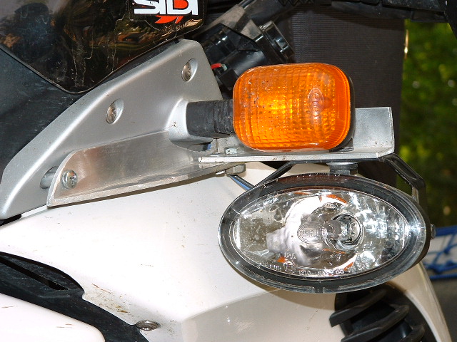
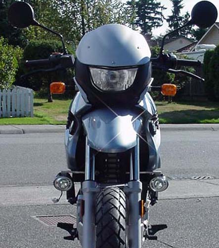
Rallye Lamps
by Rooster (Ron)
Mounting the Rallye Lamps:
 which states the
rating is 20 watts.
which states the
rating is 20 watts.
I have the BMW stock hand guards on my '01
F650GS. I used Velcro to place the switch so that I can use my middle finger to
push on or off. I had some heat shrink hanging around and used that to cover the
wire up into the instrument panel. I had to make sure that I left enough slack
for turning the handlebars. If cut to short it does present a problem.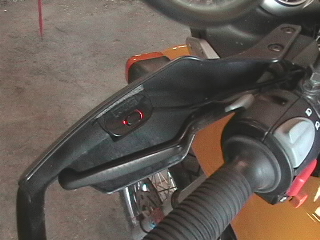
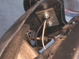
Relay: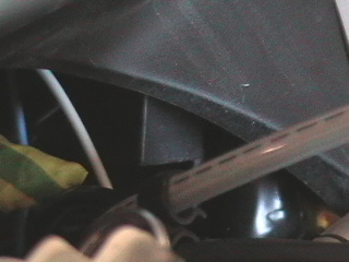
The relay is attached by a small nut & bolt.
Here is the relay mounting screw: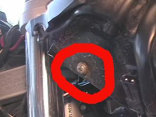
Power & Wire: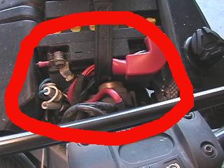

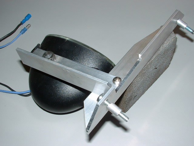
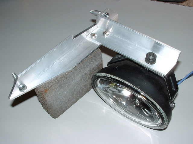
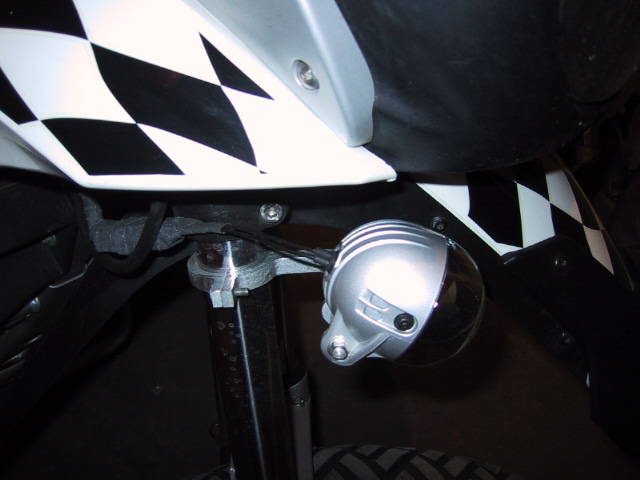
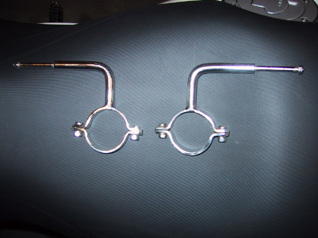
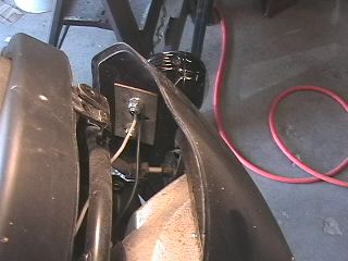
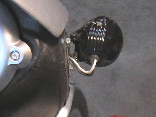
Lamp Mount: Here is the bucket resting on the front
fender. I used an old towel to protect the fender. The other two shots show the
galvanized steel plates I cut for the inside. The steel is a piece of a bracket
used to support a 4x4 for deck assembly. I filed all the edges to smooth out any
sharp or rough spots.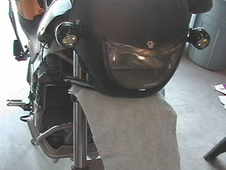
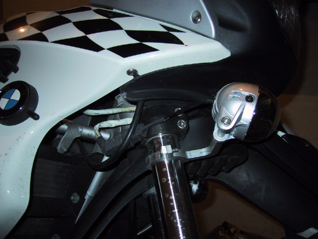
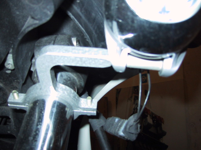
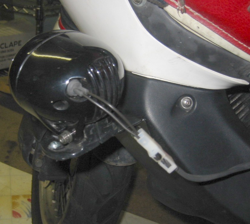
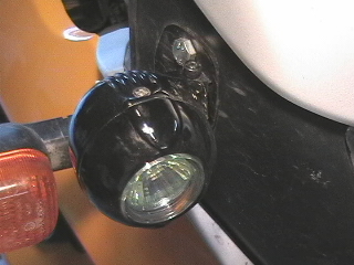
The next four pictures show the
external mount of the lamp on the right side of the bike. I used an 8mm bolt
with a lock washer, lock nut to secure to the cowling. Before I attached the
lamp I had to tap the mount with a hammer to bend to the shape of the cowling. I
also had a piece of galvanized metal about one sixteenth thick. I tapped that to
fit the inside, it was bigger than the mount so that the plastic would be stable
and distribute the weight of the lamp. 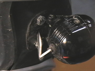
Under the mount I used a thin piece
of foam. To be honest it was a the type used to line your toolbox drawer. You
can get it form Sears or any hardware store. It is thin and does the job. I ran
the power leads directly to the battery, the fuses end up beside the ground
terminal of the battery. I thought about tracing out the high beam flash switch
and connecting there. I did not do it because I did not want to take a chance
and screw up my electronics.
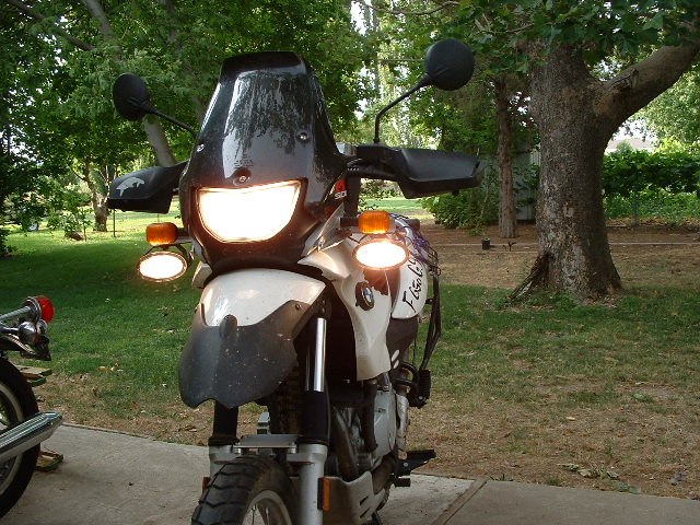
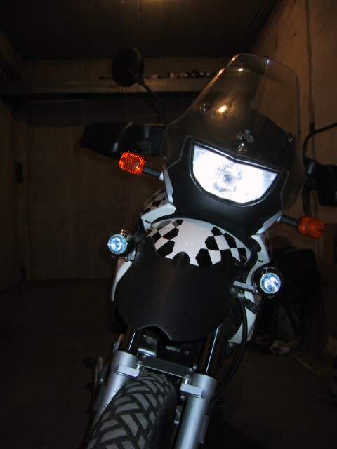
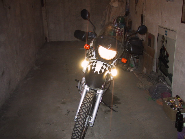
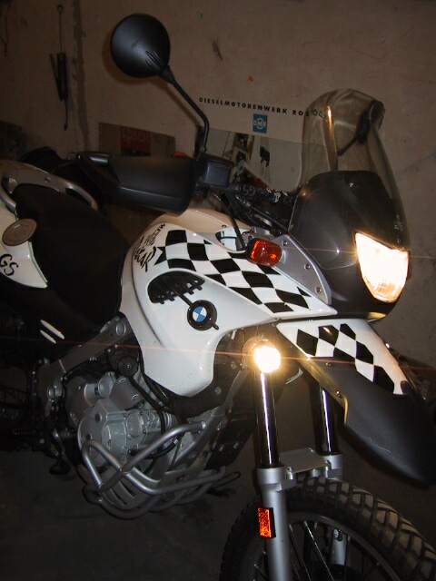
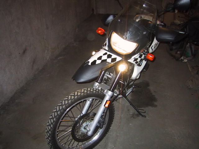
Here is what it looks like in the garage.
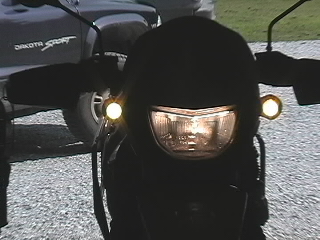
The camera is compensating for the
bright light. The lamps are decent for the money and do the job. The next step
is to provide a photo in the dark with the main headlamp covered.
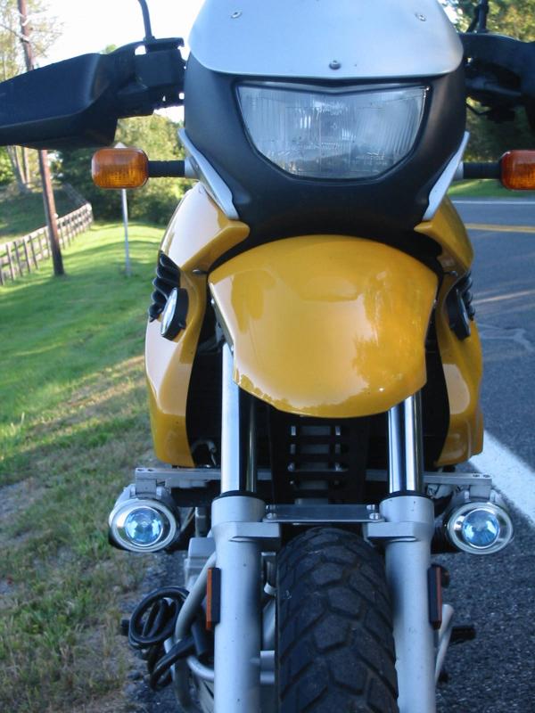
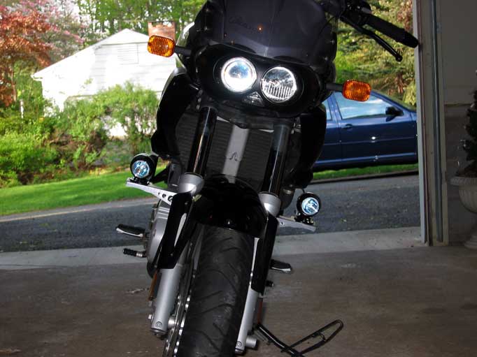
Scott, ID
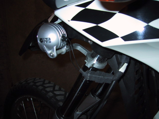
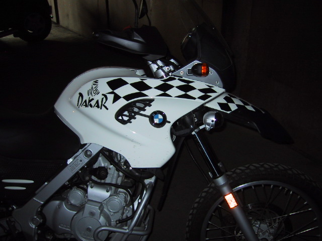
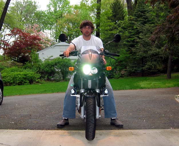
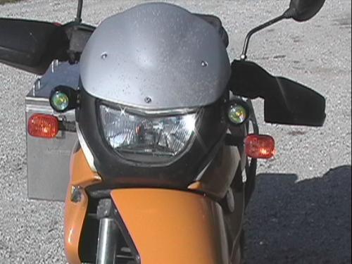
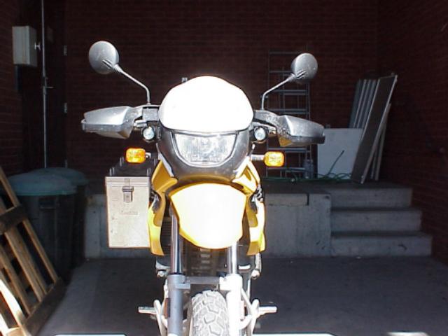
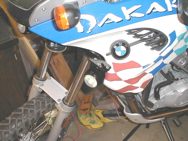
As mentioned below, I installed a set of "Rally" lights to my '02 Dakar over the
weekend (55 watts each). Below are links to a few photos if you are interested
in the outcome. In general, I am pleased with the result, and found last night
that visibility is improved by maybe 40-50%. The lights turn out to be a bit
yellow, not white; not sure what I think of that at the moment. White might be
more penetrating on those darkest nights. Yellow might be best in the fog(?)
After reading the FAQ, and staring at the bike for a few hours, I decided to
mount the lights on top of the fender housing. Well, that's where they appear to
reside; they actually are bolted to the black plastic panel beneath the
headlight as shown in this picture:
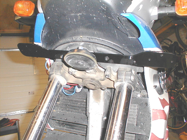
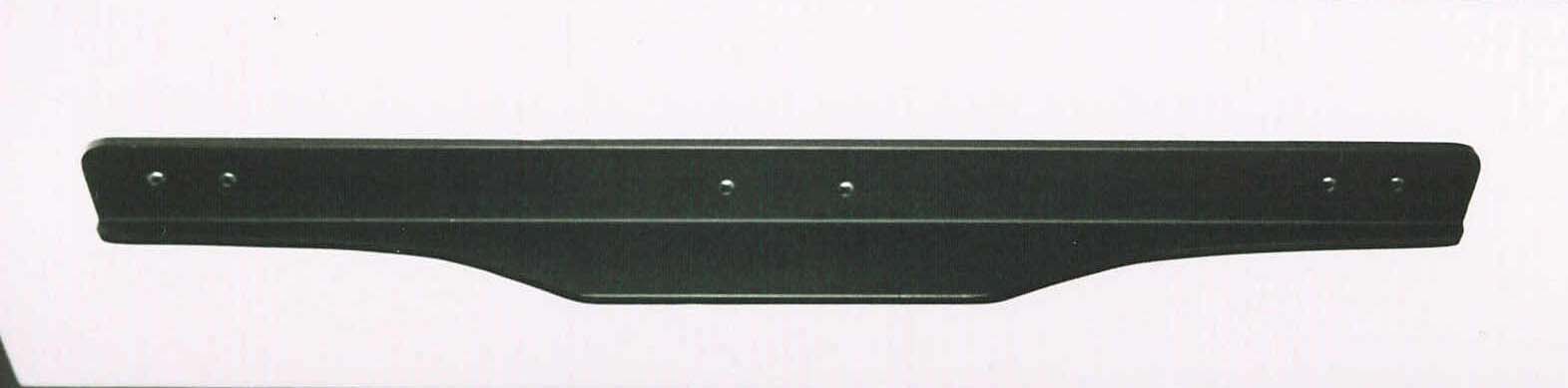
I made the bracket out of 2-inch wide aluminum bar (1/8 inch thick). Using a
bandsaw and a small benchtop belt sander, I carved the bar to fit the flat area
on top of the fender. I then painted it black using "appliance" epoxy paint
(supposedly durable stuff). The "cut-out" shape allows the lights to mount far
enough forward so they don't hit the tank area during sharp turns; assuring this
was a trial and error process that had me going back and forth from the bike to
the bandsaw, etc. I used silver screws because the tank has silver screws; black
screws might be less obvious.
After consulting with many CG members, I decided to wire the lights using a
separate relay and power source. I initially envisioned wiring direct to the
high beam wires of the headlight; bad idea as it turns out. The relay is
specific for these kinds of lights, and has 5 leads. One lead goes to the high
beam wire, and this triggers the relay to come to life when the high beam is
turned on, which in turn allows the new lights to come on also (using power from
their own wires to the battery). I did add a switch that allows me to turn the
new lights off if I want to. I might consider a switch that allows me to use the
driving lights with the low beam too . . . The relay and the light fuse were
placed near the battery; you will be happier if the fuse is located under the
seat where you can get to it. I know this to be true because I blew a fuse on my
first test ride . . . the fuse holder has been moved.
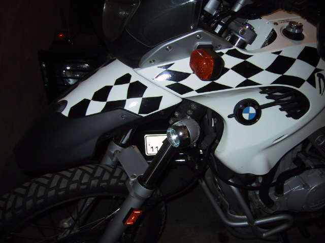
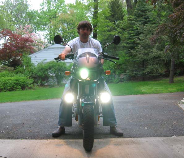
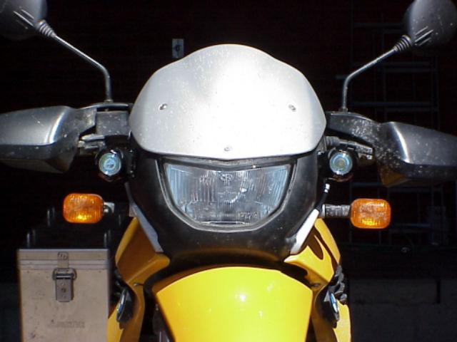
Here are two more pictures showing the final product. Overall I'm pleased to
have more light, and it was certainly worth the $100 (lights and parts)
invested.
Update 7-15-03
I decided I wanted the lights to work with my low beams, so I re-wired the (+) lead to tap into the parking light. Now I can see the side of the road when I dim my hi-beams for on-coming traffic. I aimed the aux lights a bit lower than the high beams, so traffic doesn't seem to get overly blinded by leaving them on. If want them off, I just flip the separate switch that I installed in the dash.

RCU
Light Bar for the F650GS/PD and the new F650CS
From BMW Saltlake The RCU light bar gives you a solid, convenient location to
mount your lights. We recommend PIAA 1000 and the 1100 series. Milled from
6061-T6 aircraft-alloy aluminum billet for maximum strength and durability.
Available in a bright anodized finish. This mount can accommodate almost any
lights. Screws are zinc coated to resist corrosion. Mounts into pre-existing
holes in the front subframe. No drilling is necessary. Due to manufacturers
tolerances you have the ability to adjust to multiple heights and angles. All
hardware is included.
A1. Yes, they both fit, with a little
tweaking. Gene / Barwick, Ga. USA
A2. Yep, with a little tweaking you could put
them both on. I just left the extra guard off though, it's not adding much value
as I'm not off-roading the bike anymore. Kelly #1005
23/11/01
Feedback
Feb '02
Comment j'ai installé ma lampe
au Xenon sur mon BMW F650
Le support : acier 1/8"
épaisseur, contour comme la ligne blanche et 4 trous. Pliée pour un ajustement
sur les pièces de la moto. En rouge : une épaisseur de caoutchouc pour protéger
les pièces de plastique. boulons : M5X.8 X 35mm de longueur. 
Green circle: Place for the relay and fuse
+ connection to the battery.
Blue: Wires to the switch. I used a three
position switch ( on-off-on ) so I can turn on and off the Xenon light with the
high beam switch ( very useful ) or directly using the additional Switch. You
have to be very careful with all wires and the transformer, to ensure they do
not interfere with any moving parts. Allow them to move fully in both
directions.
En rouge : le cable de haut
voltage ( 20 K volts ) entre le transformateur ( jaune ) et la lampe. Vert :
l'endroit où mettre le relais, le fusible et les connections à la bateries. J'ai
utilisé un interrupteur trois positions ( on-off-on ) Un contact pour utiliser
la lampe à meme l'interrupteur de phare de la moto et l'autre direct. Faire très
attention avec les fils et le transformateur, ils ne doivent en aucun cas gener
le mouvement du guidon. 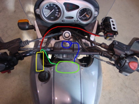
Le transformateur : J'ai coupé
l'aluminium du support original de Touratech pour avoir un module
rectangulaire.j'ai glissé le transfo dans un vieux tube fixé par un boulon et
une large rondelle plate au conduit d'air. Une petite tie rap assure que le
transfo rest au niveau. 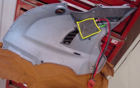
La dernière photo, où se situe
le transformateur et en blanc, un adapteur 12VDC, ( lighter plug )
Le travail en vaut la
chandelle. Si vous trouvez une facon plus simple, contacter moi pour que je
puisse mettre à jour ma page.
Feedback on the Touratech Xenon Lights
Installation is easy, only about 30-45 minutes (although I re-did the wireing twice afterwards to cut back on the extra wire length. TT give you about 5-6 times the wire you need and I just cut it back to a reasonable length)
Installation tip: I bought the starter/kill switch-block from the CS model as this also has a heated grip swicth built into it. I then used the standard Dakar heated grip switch to wire the lights. The 'low heat' position now turns on the Xenon with the high beam, the 'high heat' leave the Xenon on with both the high and low beam (I wired it to the driving light) and the off position naturally turns them off. If you don't have heated grips, just buy the standard Dakar switch from your dealer, can't be more than a few bucks and it give your switch a 'proper' home. ONE IMPORTANT NOTE on the CS switch block: it is wired diferently from the Dakar switch. Two wires need to be swapped in the plug end. real easy, but just a heads up.
If you want lots of light then the TT Xenon will put a smile on your face!
Johan
Well, what started out as a simple photograph showing the difference between my new Touratech integral HID light has grown into a more complete lighting roundup! I'm not sure how this all happened, but
somewhere between myself, fellow GS'er Steve Irby, and my good friend Domic Groves of Cycoactive/Touratech, it has become what you will see at the link below.
The idea was to compare different types of auxilliary lighting available for the GS. The benefits of which has been discussed ad nauseam on the various lists. I have had enough close calls at night to say this: If you are riding in wilderness, try your best not to get stuck riding at night. If you have to ride at night in the wilderness, your best defense against the roaming critters a buggin' right and left, is a good set of auxiliary lights that let you see as far down the road as possible. This was my reason for mounting a Touratech
integral HID light in my 1150GS in place of my high beam. This is actually a Hella integral HID headlight housing, and separate HID ballast, with a mounting kit designed and marketed by Touratech. See
my earlier post for more information on that kit.
On to the comparison. Last night at around 9pm, five of us, and one large dog, met at a highly secretive testing grounds to conduct our highly scientific and exacting lighting tests (NOT!). Actually I think we did a damn good job at showing some fundamental differences that you may not see in other testing, though I do think our external lamps could have been adjusted a bit wider. Regardless, here is what we worked with, and how we did these tests.
There were four bikes used:
My 1150 with stock low beam, the Touratech integral HID high beam, and
a pair of PIAA 520's (the more yellowish ion version of the large,
street-legal PIAA pancake style aux lights).
Steve Irby's 1150GS with the full stock lighting setup housed in a
Touratech Desierto fairing, and also a pair of PIAA 520's.
Touratech/Cycoactive's F650 Dakar bike with integral HE Projector
headlight replacement (both low and high beams are replaced by this
unit), and with both an externally mounted Touratech HID Projector
Beam, as well as an externally mounted Touratech fog lamp.
Touratech/Cycoactive's Monster Cow 1150GS with stock low beam, integral
HID high beam (same as my bike), and a pair of PIAA 540's (the
white-light version of the 520's on the other two 1150's).
The first step was to adjust all the lights so they were approximately aimed the same. We did this by lining up all four bikes in front of a flat wall with demarcations along the wall so it was very easy to see
the level of each of the lights. We aligned the auxilliary lights to correspond approximately to the height of the stock high beam. Slight variances can readily be seen in comparing the photographs and can be
attributed partially to the fact that one person was weighing down each of the four subject bikes, while four different folks were used to adjust the beams.
Once the lights had all been adjusted we rode a short distance to our solitary, isolated, secret testing grounds, a long stretch of straight, untraveled road about 25 feet wide. Using a tape measure we marked off with orange cones every 50 feet up to 150 feet (this is what I'm guessing would be an approximation of an optimum stopping distance at about 60mph, assuming your reaction time is pretty darn good. For good
measure we continued to mark off intervals of 50 feet beyond that up to 300 feet with white flowers we pulled from a tree. The greatest distance marked is 300 feet. We put the subject bike just to the right
of the crown of the road, the camera (a Nikon D2H) immediately behind it and slightly above the rider's head to show more of the road. It was mounted on a tripod and set manually at the same setting for all
photographs (except the portraits at the end of course), which was 4 seconds at f8 with the digital sensitivity set for ISO 400. Furthermore I set the color temp the same for each to give some idea of
how the coloration of the lights differ. The color temp was set at 5000K or just a bit below normal daylight. In the distance there was Kimmo Lassila (Touratech/Cycoactive) at 100 feet to the left side of
the road. At 150 feet is my lovely wife, Shaun, and our sweet bullmatiff, Diesel, who volunteered to wear his Xmas Reindeer antlers just for our test! And at a whopping 300 feet away.....that's 100
yards folks....is Steve Irby wearing his highly reflective safety vest. Weighing down all the bikes and on lighting duty is the highly capable Dominic Groves (Touratech/Cycoactive). And heading up this motley crew
on digital camera duty is yours truly.
I put the results on a very simplistic website and titled the images by the lights being used. Of those titles "1150" is my bike, "1150-2" is Steve Irby's bike, and "1150-3" is the Touratech bike, as is the 650
Dakar. In the case of the 650 we wanted to show the external lights independent of the integral headlamps, so we covered the integral lights for those shots since they were not on a separate switch.
Results were no surprise at all, other than the degree to which HID lamps give a significant edge over the stock lamps and even the PIAA's. The external projector HID did impressively well considering their
size, and bested all the PIAA's and stock lights too, coming close to the performance of the integral HID. In the pictures of the group of us the bikes line up as follows from left to right: My 1150 which is
off axis to the camera, Steve's 1150, Touratech 1150, and the Dakar 650. The two bikes on the right are on axis to the camera so you can get some idea of how bright those HID's appear in comparison to the
other lights. The HID on my bike is also on, but at off-axis angles does not appear as bright.
Pictured from left to right are me and my wife Shaun, Steve Irby, Diesel, Kimmo Lassila, and Dominic Groves. I am missing from the final pic, and Diesel is not to be confused with Steve as they have swapped
places.
Draw your own conclusions as I'm getting tired of typing here and conclusions are fairly obvious. I can only say, that in person, the differences are profound and as far as I'm concerned the money for a good HID unit like the one Touratech markets is money well-spent if you ride at night in the country.
Here's the link to the pictures on two different pages. Click on the thumbnails to get a bigger pic, then use the arrows to page through the results.
http://www.marcoprozzo.com/HID
Best to all,
Marco
Marco Prozzo Photography
Seattle, WA
Photography Website
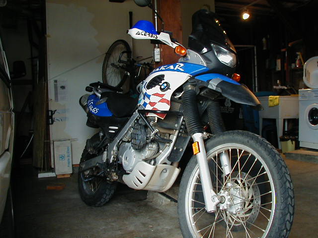
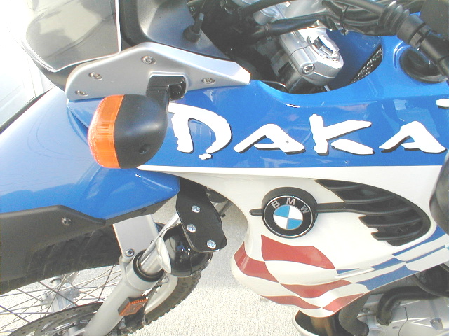
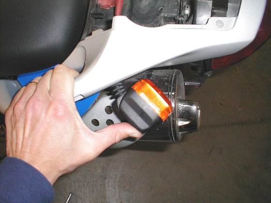
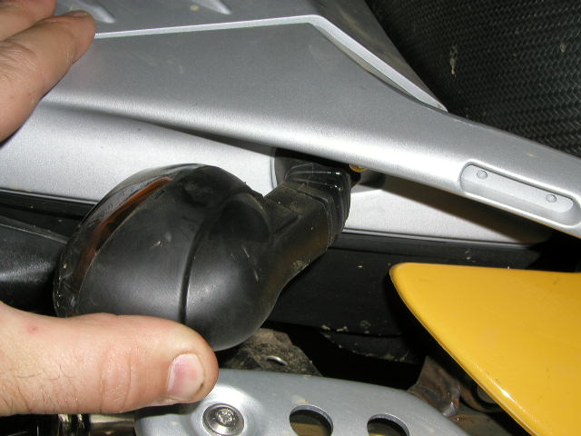
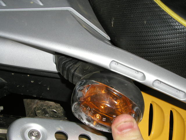
by Scott #1244 -- Boise, ID. -- '02 Dakar
Found a set of flexible turn signals that fit my '02 Dakar EXACTLY like the
original signals. The only installation hitch is that they have bullet
connectors on the wiring, whereas the BMW is hard-wired direct. You could add
connectors to your BMW harness, or solder direct to the new signal wires and
seal it up with shrink-tubing and black tape (which is what I did). They are the
Acerbis part# 14-1335-05. They come blister packed in pairs, and the local KTM
dealer charged me $20/pair (didn't try the BMW dealer). The Acerbis lens is just
a tiny, tiny bit smaller, perhaps a millimeter in each direction; they use the
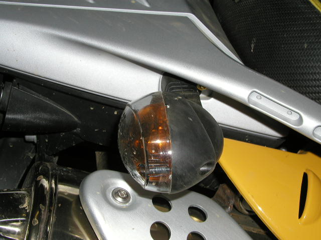
same 10W bulb. Here is a picture of them flexed (I didn't flex them any further,
though they seemed willing):
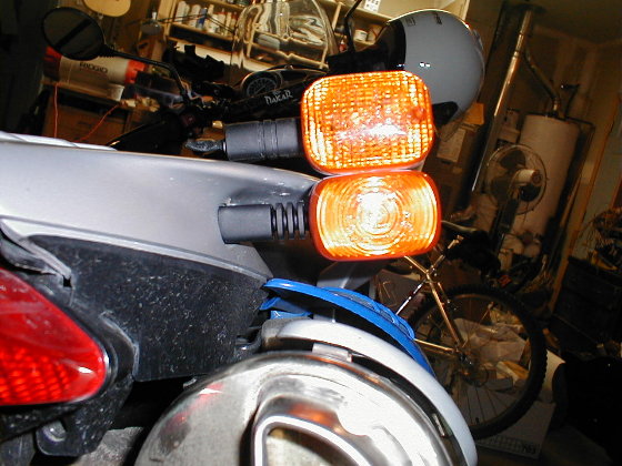
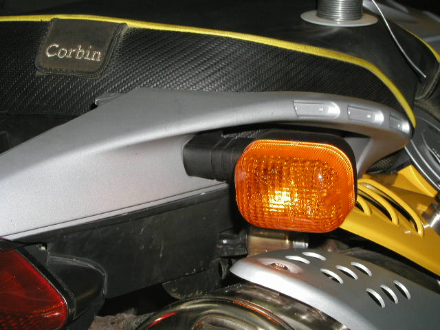
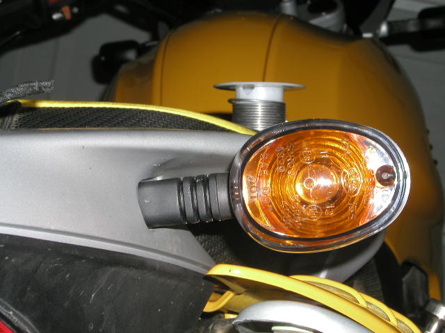
And the the new signal installed, with the original setting on top for
comparison.
I previously wrote that these were NOT flexible, and I was going to return them.
I was wrong: once installed against a firm foundation, they are in fact flexy.
The KTM's were $22/each!
Super Flexible Buell Turn
Signals on a GS
by Seacuke #1214 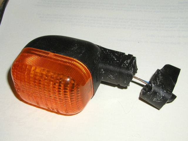
Don't let this happen to you !
It's nice to fantasize about a scenario where I am being chased by a large Black
Bear... no, make that a Grizzly Bear... through the forests of the high Sierras
in California... the Bear is gaining on me, but just before he knocks me from my
bike, I gun it, and am rewarded by the bear's claw smacking and breaking a rear
turn signal stalk instead of hitting me in the back...
Well... my turn signal stalk did break, but I would imagine it broke under the
oppression of my boot or a bungee, not from the misplaced paw of a bear whose
like hasn't been seen in California in 100 years or so.
This write-up goes over the replacement of the stock turn signals with Buell
part number "Y0503.k". I purchased mine at the local Harley dealer for 6.95 a
piece. Also note that you can use Y0503.J as well as the Y0503.K listed in my
write-up. The difference is the color of the lens - one of them is a bit darker
than the other. (Couldn't tell you which is which though).
The first part of the procedure is to remove the stock lights.
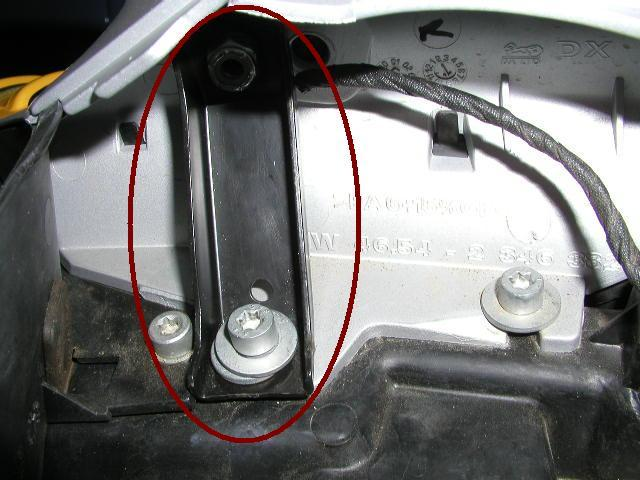
On the inside of the little tail compartment is a black metal bracket.
It should look like this.
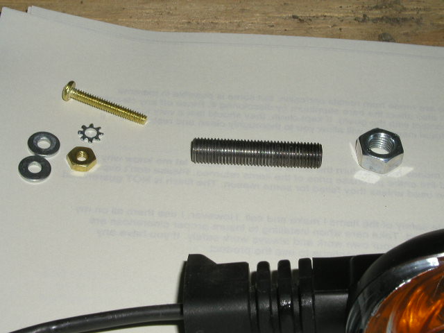

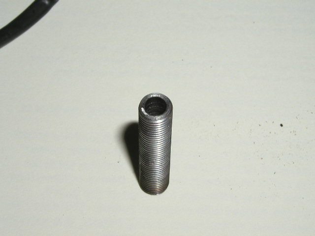
The hardware necessary to complete this task is mostly easy to get hold of,
however there is one really tricky bit. The Buell turn signal comes with an
M8x1.0 " tube" (for lack of a better word) that holds it to the Buell Bike. It
won't be useful in this application. I was fortunate enough to have a friend who
has a friend who runs a machine shop. He fabricated me a nipple out of a bit of
M8x1.0 all-thread, which he cut to 1.5 inches. Note: To do the front turn
signals, a shorter nipple is needed! A 1-inch nipple should fit fine in the
front.
In addition to the nipple holding the Buell turn signal in place, I used a 6/32
x 1" screw with a nut, a couple of washers and a lock washer to prevent the
signal from moving.
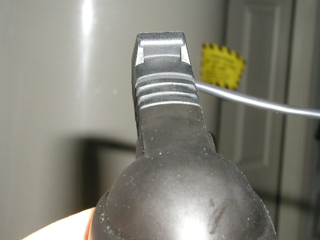
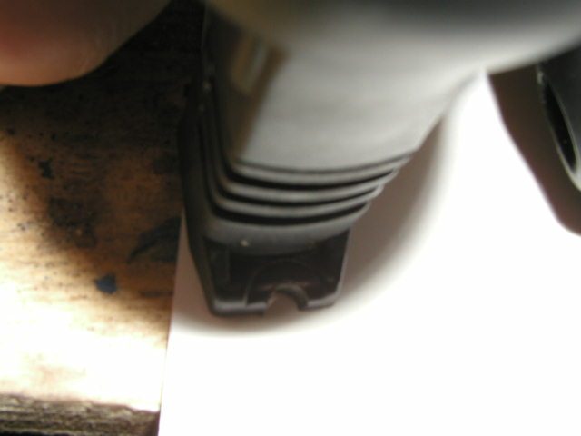
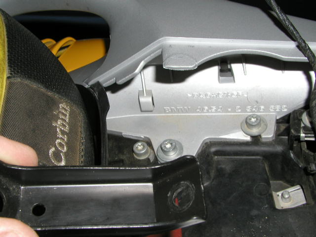
The base of the Buell turn signal is squared off as shown. To make it lock down
nice and tight, a notch needs to be cut in the base of the turn signal as shown.
Furthermore, there's a nub that needs to be cut off.
Screw the nipple into the base of the Buell signal, then thread the whole device
onto the bike. I screw the 6/32" hardware on before I tighten the 8mm (main)
bolt down on the nipple. It's easier to fine tune the angle of the turn signal
this way. 
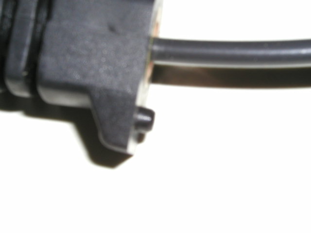
The 6/32" hardware looks like this from outside.
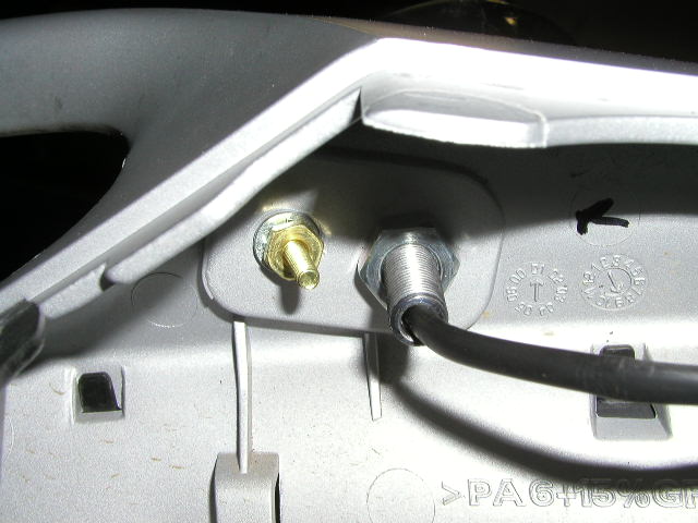
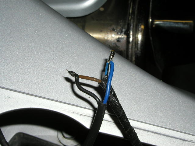
From the inside, the hardware looks like this. The last thing to do is solder
the wires, blue to blue and brown to black. Technically it doesn't matter which
wires are soldered to which, as light bulbs work the same regardless of
polarity. What needs to be soldered: the connector clips on the Buell turn
signals is different from the ones on the BMW stock signals. So I cut the wires
on both the turn signal and the bike and soldered the ends together:
The completed product. 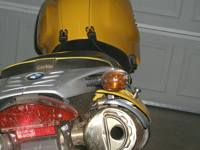
So How flexible? Real flexible, like Real flexible. I got to put my Buell turn
signals to the test a couple weeks ago when I laid my bike down. The front left
turn signal was flexed to a 90 degree angle, in other words the back of the
light was pressed against the fairing, with the bike laying atop of it. No harm
was done to the turn signal, but clearly my BMW signals would have been toast.
Dunno how much the Touratech signals are, but Buell turn signals are $6.99 each.
Cheapest and most effective mod I can think of.
Yes. Note though that you want to buy four of either
the Y0503.K or Y0503.J. The difference between these two critters is only the
darkness of the lens - the other hardware is exactly the same between the two.
The modifications are fully back-out-able if you know what I mean. You don't do
any drilling or any other kind of permanent changes to the bike. The turn
signals are permanently modified though (as per the FAQ), which is no big deal
at 5.95 (or was it 6.95?) a piece. Seacuke #1214
Grey/ black = Tail Light +
Green/ red = Brake light +
Brown = Common earth -
If your new relay is to be installed up front it might be easier to use the
circuit for the small "running light" bulb in the headlight. Todd #389