The Aftermarket Instrumentation & GPS FAQ - Classic
Compiled by Kristian #562
Updated by Scott #1244
Please read the Disclaimer before attempting any work in this FAQ.
Installing a
European Temperature Gauge on a USA F650
by Flash #412
When I was living in France, I owned and rode a
'96 F650 Funduro. It could not be imported into the USA, so I had to sell it in
preparation for leaving. In the USA, I bought a '98 F650. There are many
superficial differences. For me, one of the most annoying ones was the fact that
the Euro F650 had a temperature gauge where the USA version has a clock. I don't need a clock. I
have a wristwatch velcroed to the arm of my Aerostich. I wanted a temp gauge so
I would have more info about the state of the motor.
In April '00, I received a flier from MotoBins in
the UK. I had bought parts from them when I was living in France and was on
their mailing list. Luckily the flier was forwarded to me in Colorado. Lo and
behold, they were having a sale... eighteen percent off. Plus, as I was no
longer living in the EC[1], I would no longer have to pay VAT[2].
Immediately, I visited
http://www.motobins.co.uk and checked to
see if they had microfiches for F650 parts and service as well as the
temperature gauge and sensor. They did. I ordered. MotoBins part numbers do not
match BMW part numbers for some reason I don't fathom. At any rate, the Veglia
temperature gauge (BMW #62 13 2 346 417, MotoBins #87060) listed for 33 UKP[3]
and the sensor (BMW #? MotoBins #76500) was 9 UKP. Subtract 18% and add shipping
and the pair cost me about US$60 or so. (Refer below for another source of the
Temperature Sensor, from VDO, who make Volkswagen Gauges)
But now I had to adapt them to the bike and vice
versa...
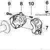
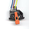
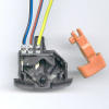
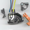
First of all, the wrench used for the temperature
switch[4] that runs the high-temperature idiot light for the USA version is
about a 24mm wrench (I used a crescent) and the one for the Euro thermistor[5]
takes a 14mm wrench. I had visions of needing to buy the Euro thermostat
housing. But... the threads are identical. Changing the sensor is a direct
replacement, requiring two wrenches. One slight caveat... the electrical
connectors on the tops of the sensors are different. Yet, with a little
chicanery, the USA wire slips right onto the Euro sensor, albeit orthogonally to
the original. The little rubber connector-cover bootie can even be coerced into
providing "safe sense."
Next, I removed the fairing to gain access to the
back of the dash. There are eight gas tank screws and ten side-panel screws.
Don't forget that there are two side-panel screws up at the front of the bike
facing down.
There are 4 screws to remove the windscreen,
which must be done to access the two large screws bolting the fairing to the
support frame. Note: you only need pull the two screws near the top facing dead
left and dead right. The two, sort of in the middle, facing front, hold the
headlight and needn't be touched to remove the fairing. Unfastening the two
large screws last puts you in a good position to pull the faring so you can
access the turn signal harness plugs on the left and right and headlight and
parking light plugs in the center. Wrassle that sucker off a there and put it
where you won't trip over it.
My clock harness looked sorta jury rigged in the
area of the time-advance micro switch. Anyway, the harness is a six pin Molex
connector which uses 0.093" pins. It was Saturday, meaning my favorite
'lectronics parts place was closed, and I couldn't find a six pin Molex at Radio
Shack. In any case, in order to get the temperature wire in there some, surgery
was going to be required. I opted to buy a pair of male[6] & female[7] four pin
connectors at RS, because they didn't have any three-pin connectors. (I hate
Radio Shack. But sometimes they are the only option.)
Note: the clock has five wires. I assume they are
12V (battery), 12V (switched), ground, set-advance, and light. From this menu,
we only selected the switched 12V and ground for the temperature gauge. I probed
around with a voltmeter and wasn't completely sure I understood what was
happening. But I certainly determined which wires were 12V-battery,
12V-switched, and ground. You don't want the battery 12V because the gauge will
draw even when the bike is not running. CAVEAT: I don't have a Euro switch to
turn off my lights. If you do, and you wire the temp gauge this way, you're
gonna turn off the temp gauge with the lights.
Using a jeweller's screwdriver, I fished down
between the metal and the plastic (of the Molex connector of the bike) to bend
in the tabs (from the pin-to-pin side), so as to be able to extract the BROWN
wire (ground) and the YELLOW/GRAY wire (switched 12V). After re-bending the
retaining tabs, I stuck these two into the female of my 4-pin connector. Note:
somewhere I have an old, busted, disassembled, telescoping radio antenna which I
prefer to use as a Molex pin removal tool. But since I couldn't find it, I used
the old, much less elegant, jeweller's screwdriver trick.
Next I went over to the other side of the dash
and yanked out the "hot" idiot light. It has two wires, one VIOLET and one
green/black. The VIOLET one goes down to the sensor. I cut the idiot light off,
because the temp gauge doesn't come with illumination and the idiot light is a
perfect fit. Furthermore, the plug removed from the hole[8] in the gauge fits
the void left by removing the idiot light from the dash panel. (While I was in
the neighborhood, I wrapped a small piece of electrical tape over the highbeam
indicator light because it is just too damn bright for me at night.) If and when
I come across a good substitute for the idiot light, I might get it and wire it
in as an indicator for my hot grips. This is totally unnecessary, but the
indicator icon IS a little thermometer.
I soldered a wire to the violet wire and taped up
the connection all neatly, along with the green/black to keep it out of harm's
way. I ran my new wire over to the vicinity of my new connector, cut, stripped,
soldered on a pin, and installed it in the new connector..
There is one nut that holds in the clock that
must be reused on the temp gauge. Be sure not to lose the washer when you remove
the nut. Also, there is an o-ring up against the bezel of the clock that should
be transferred to the temp gauge. The advance-set micro switch is pressed in and
just pulls out.
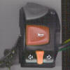
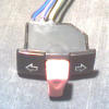
The temp gauge itself has the aforementioned
plastic plug in an illumination hole as well as three spade-type automotive
quick connects. These connectors are labeled with icons for + and Ground, and
the third says "SENS." If it is not clear what you should hook where at this
point, you shouldn't be doing this without supervision.
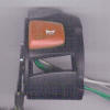
I noticed that the gauge fit nicely into the hole
vacated by the clock. However, it looked like there were certain cutouts not
quite positioned perfectly for the temp gauge connectors. Since I had a
selection of Stacons (crimp-on ring or fork, wire-to-screw connectors) on hand,
I opted to make a small harness of my own and do away with the quick-connects.
Fortunately, the three are each held by a nut, and can be removed quite simply.
I patched my idiot light / illuminator into the hot and ground leads. Everything
worked out and it seated completely. The only drawback is that I'll need to
withdraw the gauge to change the bulb when it burns out. But that can be done
without removing the fairing, as I planned ahead enough to allow sufficient
slack in my harness. I could have drilled out the other location indicated on
the back of the instrument. But I figured that was more hassle than it was worth
for all the bulb changing I'll be doing. Hell, I put about 80k miles on an
R80G/S and never had to change the bulb in the Tach.
Before I reassembled the fairing, I tested the
instrument by pulling the bike outside and firing it up. When the key is turned
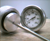
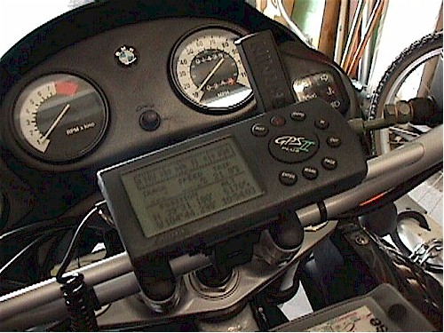
on, the gauge comes up slightly. I started and ran the motor at idle while I put
all my tools and supplies away, pausing from time to time to note that the
needle was rising. There are no numbers on the gauge; nothing but the word
"TEMP," at about the midpoint of the needle swing. My goal was to run the bike
until the fan came on and then went back off. The fan came on when the needle
was roughly midway, centered on the word, "TEMP." After running for two minutes
or so, the needle dropped to where it was ever so slightly below the "T" in the
word when the fan stopped.
In heavy, downtown, summer traffic in France, I
had seen the needle approach the red zone on my old bike, but never quite enter
it. To me, this is better than a simple idjit light, knowing you're getting
close to over heating. Besides, it is always a real pleasure to hit an open
stretch of road after being stuck in traffic when the temp is up and watch the
needle suddenly plummet. Also, with my US F650, I am never quite sure when to
turn the choke off fully. Occasionally, I have turned it off, and then back
halfway on, and then forgotten about it. With the temp gauge, I'll see when the
motor has attained proper operating temperature and turn off the choke, as I
used to do in France.
A few notes about reinstalling the fairing... The
first time I removed fairing, it took a long LONG time to reinstall. And I
munged up some of those stupid clips along the way. I finally figured out NOT to
use any power screwdrivers when reassembling. I finally figured out to stick the
hex wrench in the hole to make sure everything is all lined up BEFORE trying to
insert a screw. And I got some extra clips to keep on hand. In a pinch, you can
always swap a mashed one from an area you can't get behind to hold it during
assembly with one that is, say, from the lower panel, which you CAN get behind.
I never tighten any of the body screws any tighter than I can get them using the
SHORT side of the Allen wrench in my fingers.
In the end, the bike was back in one piece,
sporting a new TEMP gauge where that stupid clock used to be. The gauge looks
every bit as good as stock because, well... it IS. Click
here for a (fuzzy)
picture of the gauge installed.
[1]
European Community
[2] Value
Added Tax, varies, but runs around 15%, except on export items.
[3]
United Kingdom Pounds, aka Pounds Sterling, about $1.65 each at the time I
ordered
[4]
Switch says: 115C, 81-25, F7, Jaeger
[5]
Thermistor says: 120C, 04-03, K3, Veglia Italy, 12-24V
[6]
274-224, about $1.25
[7]
274-234, ditto
[8] It is
a little rubber plug, about 9.5mm or 3/8" in diameter, with two wires, that
holds a tiny instrument-type bulb.
[9] Ai
putain! I forgot to write down all the numbers from the stickers on the gauge.
C'est la vie. Le prochaine fois.
Finally, thanks for reading this. That's why I
wrote it.
Here are some additional comments
Fede (Spain)
By the way about your good article. The temp
displayed is more or less as follows: 1) The bottom indicates 40C. 2) The middle
between 1) and the horizontal position marks 60C. 3) The horizontal position,
over the word TEMP, indicates 80C 4) The beginning of the red line shows 100C 5)
The end of the red zone shows 120C.
The engine runs always over 50C. Below 10-12C of
external temperature, takes about 3-5 minutes to reach this temperature, and
below 0C, till -6 or -7C runs slightly down of 50C. Over 12-13C takes only 2-3
minutes to reach the work temperature. The fan starts slightly over 80C, perhaps
85C. In about 1-2 minutes, or less time, the temperature goes down 80C,
including those days with external temperature about 40C, and/or intense city
traffic. If the temperature is hot, about 80C, takes a few seconds (20-30) to go
down when the bike runs over 20 Km/h. After riding a lot or in a hot day, if the
fan is on, I let to run during a few seconds before stopping the engine, at idle
revs. This is my own experience. Perhaps these ideas can be helpful for
somebody... Specially those of you whose bikes lack of thermometer. But the
cooling system of the F650 is one of the most efficient... Regards, Fede
Can Yucel (Turkey)
First thanks for your extremely understandable
explanation of clock - temp gauge swap on
www.f650.com. When I replaced my clock with a temp gauge on my 98 f650 I
checked all electrical connections by myself but later found that everything was
clearly explained in your writing. But I think there are several points that
must be reminded for European riders who are about to install a temp gauge. Not
all of the euro f650s come with temp gauges but all of them are fitted with euro
head light switches. Therefore switched 12 V (+) (yellow grey cable) in your
writing refers to head light switch switched 12 V(+). If you want your gauge to
operate when you turn the lights on, no problem but activating the gauge from
the ignition switch requires additional 12 V (+) source from the accessory plug
or somewhere switched 12 V(+). Existing switched 12 V (+) can be used for
illumination light on the gauge. Instead of Veglia temp sensor, Volkswagen
temp sensors made by VDO ( with same thread, size, resistance and temp
degree, also costs much less) can also be used. Regards Can Yucel,
DWM (US)
Yes they will work, BUT the gauge is $54.00 & sending unit is
$29.00 for a total of $82.00. And the dealer claims Aprillia is next to
impossible to get parts. He does not stock these items (I didn't think he would)
and claims 3 weeks if their in a US warehouse, or 6 to 8 weeks if they have to
come from Italy. The way I figure it $72.00 bucks from Motobins including
shipping. Its no mystery why Aprillia is having a hard time getting shops to
take on their line in this country. Very weak effort on Dealer support. DWM
Albany, NY USA
Adding an Oil
Temperature Gauge
Thumperstuff Oil Frame Tank Gauge
Peter #233
4/5/99
 Want
to keep track of engine oil temperature? It is easy....just replace the stock
dipstick with an oil temperature dipstick from Thumper Stuff (www.thumperstuff.com).
Ask for part #1190. Europeans have known about this for some time; it is now
available in the USA. About $45. You may have to reposition the dial for easy
reading.
Want
to keep track of engine oil temperature? It is easy....just replace the stock
dipstick with an oil temperature dipstick from Thumper Stuff (www.thumperstuff.com).
Ask for part #1190. Europeans have known about this for some time; it is now
available in the USA. About $45. You may have to reposition the dial for easy
reading.
Q. Why can't they have a cold
level to check just like almost every other bike or car made.
A. Because the Rotax motor has a dry sump.
And that means that you can never be sure exactly WHERE the oil is on a cold
motor.
Thumperstuff Oil Gauges: Opinions
-
I'm not sure why you want oil temp and not water
temp. Either one will tell you the state of the motor. If you lose your oil, the
screw-in type oil temp gauge will lie. If you run out of oil or water, the water
temp gauge will let you know that the motor is overheating. I just found a cheap
solution for a water temp gauge... a Veglia water temp gauge for a Fiat will fit
nicely in the hole vacated by the clock. I've yet to do the wiring harness for
it and parts list. I've yet to take the pictures. But the gauge costs well under
US$20. Per Can Yucel's note in the Classic FAQ, if a VDO sensor can be had for
~$5-10, then the whole thing will end up costing me less than one of those
inaccurate (lying) dipstick thingies. I'm contemplating making up a kit
containing all the required parts along with a proper wiring harness so that it
just drops in where the clock used to go. Anyone interested in a complete "kit"
for... oh... US$50? (Of course, I'll also do the write-up for the
do-it-yerselfers.) Flash 412 (CO)
-
I
received my Thumper Stuff Oil Temperature gauge for my pre-GS bike. I had
previously tried ordering though the mail and via e-mail without success. I
finally ordered by phone, 360-563-0376, and it arrived at my door within 3 days.
I am very happy with the gauge. The gauge is a bit small for fast reading on the
road (for my poor eyes) but seems very well made, even if you do have to scratch
the high and low oil level on the probe. It only costs $45 plus $4 shipping. I
had a similar gauge on my 1977 Yamaha SR500 and paid $60 for it over 20 years
ago, so this is a really good deal. I rode my bike at 70 mph for 20 minutes and
could only get it up to 180F. Another 10 minutes on local roads and it went up
to 190F and stayed there (in 60F weather). As a reference, my air-cooled SR500
would show 220F on the freeway, and never dropped below 190F, even in 35F
weather at 70mph. Looks like the F650 has a pretty good temperature control
system. Richard #230
-
Just Purchased a Dipstick with
the Temperature Gauge from Thumperstuff (part # 1190). I know this unit is
discussed in the FAQ's, but I wanted to post a thumbs up here on the product. If
you have a classic and you want to keep up with your engine oil temperature, I
highly recommend it. It even looks trick. Anyway they are listed in the links
page. Doug 99F GA #1206
Oil Level Marks:
-
I scratched
my probe last night using a hacksaw (instead of the recommended file). It seemed
easier to do it this way. I just aligned the existing dipstick with the new one
and marked the high and low lines with tape and used the hacksaw blade to make a
scratch line all the way around the temp probe. Richard #230.
-
I have a oil temp gauge on my 98 F650. I like it -
sort of - I like the idea of being able to see the oil temp on big trips. But it
was kind of a pain to etch high-low marks of the gauge. I'm not really sure if I
got the marks right. I got it from ThumperStuff.com it was like $30 or so.
iphead
-
Hey, marking the new gauge probe is a piece of cake!
You lay the new gauge with its probe next to the stock dipstick and make marks
on the stainless shaft where they should be with a pen. Then make them permanent
with the three corner file. What could be easier? Johnny #862
-
I agree with Johnny, it is a piece of cake to mark
the gauge stem. I did it the same way he did in just a few minutes. Leo#699
2000F
Max. Temperature:
-
The gauge is
redlined at 240F, which sounds about right to me, for synthetic oil. Dino oil is
best kept below 230F. The best temperature is around 190 to 200F. You want the
oil hot enough to cook out any water vapour that builds up in the crankcase and
oil when the engine cools down at night, but not too hot that the oil will start
to "breakdown". Richard #230
-
You also need to be concerned about engine blow-by and condensation creating
acids in the oil that will attack the bearing materials. Even synthetic oil will
not keep this stuff at bay for too long, under short-haul riding conditions.
-
Seeing that my bike's oil will be anywhere from 170 to 245 at full temp,
depending on the weather and conditions, I'm not sure I agree the cooling system
is all that great. running at a good clip in warm weather will usually get the
temp up to 220-225. today, in cool weather, it barely reached 190. but I've hit
245, and my coolant's always been at the right mix and level. Mark #403
-
One of the
most interesting thing's I've noted is that I can run forever below 6K with just
about any load on any terrain and my temp hovers close to 200°. The second I go
above that, temp starts to climb. Sometimes in the summer with a full load up to
250° That's another reason I use Synth. The observations I noted occur
regardless of ambient temperature. They just happen quicker. If I ride close to
red line on a 50° day, it still gets up to 240°-250° eventually. David#476.
-
I obtained a oil temperature dipstick through
thumper stuff...cool. Now just what is the operating temperature range for the
non-fuel injected 1999 F650?
-
With outside temps in the 60-degree range I see 170
to 190 depending on the amount of fire (throttle) being used. So far on a day
with maybe 90 to 95 degrees out and traveling at say 80 mph's I've seen 220 on
my Thumper Stuff gage. That's been the highest so far, hope not to see much
higher and if I do I'll be slowing down. Good Ride'n Bill, Wamer #1021 CA.
-
I've hit 235 when off-roading. ambient temp and
riding conditions make a big difference. you can always check your dipstick by
sticking it in boiling water. 212 degrees, minus approx 1.5 deg for every 1000
feet elevation, something like that. The dipstick can be calibrated by holding
the bezel firm with your thumb, and rotating the dipstick with pliers. (this
only applies to the non-liquid filled version, don't know about the other one).
-
I have been using the Thumperstuff oil temp gauge on
my 1997 bike for the past couple of years and I have been very happy with it. It
is nicely made, but I agree with Geoff, scribing the oil level lines on the
gauge probe was a little irritating, but I don't blame Thumperstuff for not
wanting to do it themselves. I don't have an order number. All I did was to give
them a call and my credit card number and it arrived in 3 days. Before that I
had printed out the order form and mailed it with a written request and never
received a reply. P.S. 23 years ago I bought a very similar gauge for my Yamaha
SR500, which also had oil in the frame and the filler behind the steering stem,
and paid $65 at that time, so I figure that $45 is a pretty good deal, what with
inflation and all. I find it interesting to note that the oil temperature drops
around town, while the coolant temperature goes up and the oil temperature goes
up at high road speeds, while the coolant temperature goes down. (No I don't
have a coolant gauge, but I have had other bikes that do and that is how things
work in the engine coolant business.) Richard #230
-
It is a consensus. Thumper gauge, same temps as
above. me.
-
Me too. Richard #230
-
I have had the same experience as Warmer. Leo #699
Utica, NY - 2000F
-
Ya know, I have the Thumper stuff gauge too. Same
ranges too. That said, oil temp ain't the best way to measure overheating on a
water cooled motor. By the time the temp really goes up, (more than the 220-230
that some get), it's too late. Water temp is a better way to follow this.
However the gauge is a pretty geegaw to look at. Nate
-
I can cruise all day
at up to 5000 rpm and my temp will run at 200˚ City traffic in Vegas at 100˚
ambient, hiway in spring, summer or fall. Whatever, never budges. Almost
immediately if I go above 5K, the temp starts to rise and in the summer it
will reach nearly 250˚ I've always assumed this was a summer only phenom, but
yesterday I took a nice long ride ending up with 50 miles of freeway home and
it happened at 60˚ I run Synth so I'm not really worried about the oil
breaking down. David #476, '99 F650.
-
I have found that my
oil temperature goes down in slow heavy traffic, while my coolant temperature
goes up. On the freeway at speed, my coolant temperature goes down, while my
oil temperature goes up. In the City I usually see about 170 degrees, while my
fan hums in gridlock. On the freeway in 100 degree weather and at 80 mph last
year, I saw 230 on the gauge. Richard #230: 1997 Funduro.
-
I've hit about 250
with the throttle WFO, into a serious headwind in Nevada which kept my max
speed to about 85mph. regular hard riding often gets me to 230, while early
morning commutes sometimes don't go much over 180 (as measured in the frame
tank). i would say right around 200 is typical/average, but going over that
doesn't take much on the throttle. I also use synthetic. Mark #403
-
I gauge my coolant
temperature by when the fan comes on (which it only does in heavy, stop and
go, traffic). I was just surprised that the oil temperature would be so
(relatively) low under those conditions. I too find my oil temperature between
170 and 180 during my morning commutes, after a 10 mile run on surface
streets. It only goes up when on the freeway at high speeds (that would be
when the engine is under a load and at high rpm). The hottest I have ever
seen, while running on 280 at 80 mph in 95 degree heat, was 230 (but that is
at the filling cap, not at the bearings). That was on level ground. If it had
been up hill or into a headwind, I am sure it would have been higher. I am
using Redline synthetic 20-50wt oil (which can take that heat). I am not sure
I would want to use something like Pennzoil in the F650. A friend of mine just
overhauled a Japanese engine that had been using Pennzoil and he said that the
engine had spun a bearing, the cam surfaces looked like h*ll and the oil
seemed burnt and there were black, crusty, deposits on the engine surfaces.
Richard #230
-
Oil properties are
clearly defined in terms of - just to mention a few - oxidation rate,
viscosity index, .... Oils have a life span, btw this is the reason why we
have to change it and not just refill when going low. The basic rule of thumb
goes as follows: for every 10°C above 70°C (again metrics guys, it's so easy)
the oil life span is cut in HALF...... Sad news hmm but true story. In
other words if you ride your bike at hot oil temperatures for extended periods
of time you should seriously consider changing it (the oil of course, not the
bike) at shorter intervals. Cheers, Fred, '95 F650, Holderbank, Switzerland.
-
For those of you
with pre-GS's and oil temp gages, what is your running temp. I can cruise all
day at up to 5000 rpm and my temp will run at 200° City traffic in Vegas at
100° ambient, hiway in spring, summer or fall. Whatever, never budges. Almost
immediately if I go above 5K, the temp starts to rise and in the summer it
will reach nearly 250° I've always assumed this was a summer only phenom, but
yesterday I took a nice long ride ending up with 50 miles of freeway home and
it happened at 60° I run Synth so I'm not really worried about the oil
breaking down, but what's the consensus on this? Should I worry? David #476,
'99 F650.
-
I have found that my
oil temperature goes down in slow heavy traffic, while my coolant temperature
goes up. On the freeway at speed, my coolant temperature goes down, while my
oil temperature goes up. In the City I usually see about 170 degrees, while my
fan hums in gridlock. On the freeway in 100 degree weather and at 80 mph last
year, I saw 230 on the gauge. I gauge my coolant temperature by when the fan
comes on (which it only does in heavy, stop and go, traffic). I was just
surprised that the oil temperature would be so (relatively) low under those
conditions. I too find my oil temperature between 170 and 180 during my
morning commutes, after a 10 mile run on surface streets. It only goes up when
on the freeway at high speeds (that would be when the engine is under a load
and at high rpm). The hottest I have ever seen, while running on 280 at 80 mph
in 95 degree heat, was 230 (but that is at the filling cap, not at the
bearings). That was on level ground. If it had been up hill or into a
headwind, I am sure it would have been higher. I am using Redline synthetic
20-50wt oil (which can take that heat). I am not sure I would want to use
something like Pennzoil in the F650. A friend of mine just overhauled a
Japanese engine that had been using Pennzoil and he said that the engine had
spun a bearing, the cam surfaces looked like h*ll and the oil seemed burnt and
there were black, crusty, deposits on the engine surfaces. Richard #230
-
I've hit about 250
with the throttle WFO, into a serious headwind in Nevada which kept my max
speed to about 85mph. regular hard riding often gets me to 230, while early
morning commutes sometimes don't go much over 180 (as measured in the frame
tank). I would say right around 200 is typical/average, but going over that
doesn't take much on the throttle. I also use synthetic. '99 F650, Bay Area,
California. mark #403
Sump Plug
Oil Temp Gauge
Sump Plug
Oil Temp Gauge: This site shows a Sump Plug Gauge. To date no one knows if
it fits OUR sump. "This functions the same as
our water temp gauge. It comes with a variety of adapter sizes to fit most
models by replacing the stock drain plug. Order by the size of plug threading.
Also available adapters only."
Feedback
-
Check this out:
http://www.shindypro.com/catalog/each_q_ptype.key31.html I got the link
from the R1150R site. Apparently, the oil gauge sells for around $80 from a
dealer (I gather the price is a bit flexible). What they like about it is that
it replaces the oil drain plug and therefore is very easy to install, however
some questions remain how useful it is knowing the oil temperature at the
bottom of the sump. It is just as likely that you are measuring the
temperature of the sump engine case. No one has tried the water temperature
gauge, as R-bikes are not cooled by the water vapor that condenses in their
big engine cases. Richard #230
-
The Shindy is $100US at Dennis
Kirk.
http://www.denniskirk.com/powervendor/details/detail.asp?serverid=nlStreet&PartNo=40663
Logan's Ride
Aftermarket Coolant Temperature
Gauge

Sump Plug
Coolant
Temp Gauge: This site shows a Replacement Coolant Temp Gauge. To date no one
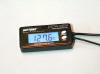
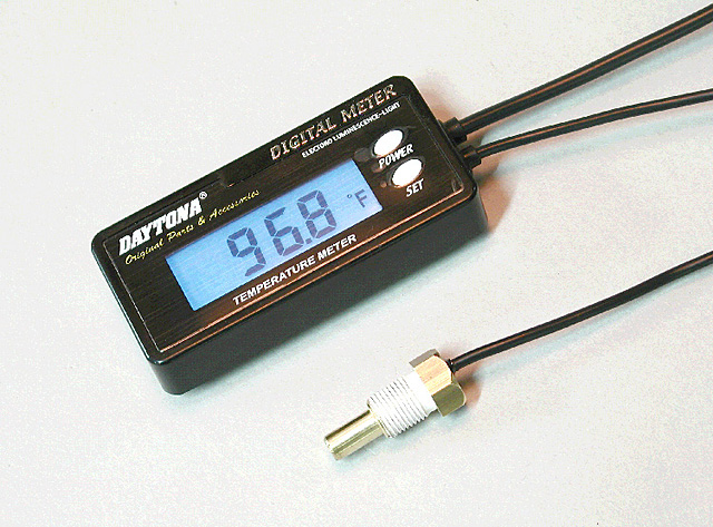
knows if it fits OUR bike. "Compact
size digital gauge clearly indicates the actual temperature. Switchable to
Fahrenheit or Celsius, and has blue backlighting. Velcro mounting makes instant
installation on any flat surface. Fit for most Japanese liquid-cooled models.
Available replacement sender."
Aftermarket Fuel Gauge
Flash #412 & Andy Leeds UK #982
14-Nov-01
-
You could add a low level indicator light with this:
http://www.uoguelph.ca/~antoon/circ/sensor3.htm
-
If you want to try it, run a length of clear hose
from the tap and back into the overflow connector at the top of the tank. The
fuel will run up the pipe to the same level as the rest of the tank. In theory a
good idea, but finding the right pipe and fittings and stopping idiots using the
pipe to steal the petrol defeated me before I had chance to try it. An actual
fuel gauge needs a sender in the tank with the right connections and a wire to
the gauge. Not a DIY job.
-
Failing that use the odometer!
GPS Warning
8/7/99
Got a GPS? Going
to be out on the 21 and 22 August, 1999? Better bring a map if you have an older
GPS. You've heard of the Y2K bug, well there is a GPS bug too.
 It
seems that every 1024 weeks (~20 years) the GPS
satellites
reset their week counters. On August 22, that count will reach 1024. However the
satellites can only count to 1023 so they'll reset to 0 instead. This will cause
many older GPS stop working or appear to be working but displaying inaccurate
times and positions. 20% to 30% of the GPS's made are not suppose to handle this
rollover to 0.
It
seems that every 1024 weeks (~20 years) the GPS
satellites
reset their week counters. On August 22, that count will reach 1024. However the
satellites can only count to 1023 so they'll reset to 0 instead. This will cause
many older GPS stop working or appear to be working but displaying inaccurate
times and positions. 20% to 30% of the GPS's made are not suppose to handle this
rollover to 0.
So if you
WERE out on the weekend of August 21 and 22
1999 and your GPS WAS acting goofy.
At least you'll know why and you can then explain it all to your buddies.!
[These
comments were prepared at a friend's request. He is shopping for a GPS. Your
experiences will be different from mine but here are my comments. I do not
pretend to cover the use of a GPS for off road riding.]
Choosing a
GPS unit is only step one in the process. Wiring, mounting, memory and
supplemental mapping are also very important issues. Based on my experiences,
these notes are directed to a GPS for street riding, not dirt or trail riding.
Having a GPS
adds an interesting dimension to your riding. It will not do much on roads that
you know really well. However, for any day riding away from your local area and
for any multi-day trips, they are great to have. You always know where you are
and where to go. At any intersection or stop, you can zoom out to see where to
go. The GPS soon becomes the map of choice because it can minimize or eliminate
errors in road directions. You do not have to carry multiple maps, especially on
a long trip.
Wiring
While most
GPS units are designed to run on batteries, it is not recommended. The batteries
will not last for long durations, particularly with a back light turned on as is
needed for daytime viewing most of the time. Also, the shock and vibration with
the weight of the batteries is not desirable.
Direct
wiring to the battery is preferred. That allows the rider to leave the GPS unit
on while stopped. This keeps the elapsed time counters running for measuring the
day’s performance. You can also check upcoming locations and distances while
stopped without having to turn the key on. Of course, the downside is having to
remember to turn the unit off at the end of the day. Since it is often removed
at the end of the day, this is not difficult.
Mounting
Location is
key. You should first search for the best location for the particular bike. Take
into account other instruments, view, radar detector location, etc. Then search
for a mount that is specific for your GPS unit and will work on the bike. On the
handlebar in front of the tank bag (but not obstructed by it) is a good
location. The GPS starts taking the place of you map so it is natural to look in
that area.
I strongly
recommend the Touratech Handlebar mount for StreetPilot from CycoActive. http://www.cycoactive.com/gps/gps_mounts.html#ttsp
This mount is just the best. It is hard to appreciate what it does for you when
you are first buying a unit and spending $$$ on everything in sight. In use, it
is very secure, easy to use, holds your antenna in place, etc.
Memory
The Garmin
StreetPilot that I use has a module for memory expansion. Selection of the
module(s) is based somewhat on your expected riding use. For your home turf, you
can purchase a smaller memory module (16MB or 32MB) since the StreetPilot has a
map limit anyway. Each "map" covers a county in Arkansas but not in Colorado. It
seems to vary with the level of detail on the CD for the area you are using to
create the specific map set. For Arkansas, I can get my natural riding area in a
13MB file to download to the GPS. But you can only have one map set loaded at a
time in a module. Therefore, a larger memory module may not be needed unless the
map set has a lot of detail in it.
Also, if you
are going to cross country and want the extra detail from a Map Source CD map
set, you will have to figure out how to load the different map sets that you
will need. You can rely on the standard base map that comes with the unit for
freeway and large state highway riding, etc. However, for more detailed mapping,
you will want to have map sets from a CD. Unless you are going to have a laptop,
etc. with you in the evenings, this will not be possible. A solution is to
purchase multiple memory modules and preload them with detailed map sets from
the CDs for the areas that you want to detail. You should purchase one memory
expansion module first to determine your map set download needs (and to practice
on). Then you can purchase more modules as needed for trips. You can erase and
reload map sets as desired. If you took a "three module" trip, you would preload
all the modules and simply switch them out in the GPS as you traveled. You could
erase and reload different map sets for other trips.
A strong
recommendation is the USB Data Card Programmer. This lets you use a USB port for
the downloads. Without it, the process is very long. And without the USB setup,
you have to put batteries in the GPS while downloading since the unit is off the
bike and hooked to your computer. With the USB setup, only the memory module
goes in the USB holder and once loaded, you simply insert it into the GPS unit.
Supplemental Mapping
These are
Map Source CDs for Garmin units. Make sure you are getting the correct CDs for
your GPS. Start with the U.S. Roads and Recreation. It has the needed detail for
the whole U.S. From that CD, you will create map sets as desired. With the
memory modules, you can save various map sets on your computer and quickly
download to modules as desired.
Stay away
from the MetroGuides. They are for cities - not of interest very much for
motorcyclists. You can buy appropriate CDs for most
countries if you ride in Canada, Europe, etc.
GPS Unit
I have used
a GPSIII+ and a StreetPilot (B&W). The GPSIII+ is a great little unit if you
want small size and are satisfied with little memory (1.6MB). The StreetPilot is
great with all the features you will want and is not much more expensive. The
downside is its larger size. The color unit has a smaller screen and did not
seem worth it to me. The new StreetPilot III is very expensive and offers voice
commands. That does not seem very desirable on a motorcycle. I save my earpiece
for my radar detector.
Where to buy
This
probably changes often but I recommend two sites after you peruse the Garmin
site [which is hard to navigate].
You can find
more by searching GPS, or Garmin on any search engine. As usual, shop carefully.
Watch for saving shipping costs by aggregating your purchases as much as
possible. Not all the sites carry all the accessories such as the Map Source
CDs, or the USB unit.
Notes:
DHP #711
Garmin Cable Info:
Etrex info:
-
I have
owned several Garmin units and my favorite overall is the GPS III+. It's base
map
is good, however it has limited memory for downloads. I have owned an Etrex
Vista, which is excellent with lots of memory, I have owned an Etrex legend that
is nearly identical to the Vista, except it does not have a built in compass or
barometer, which are not needed for use on a bike, it also has 8mb of memory
which is 1/3 of the Vista memory but is enough for me. The Etrex series is
excellent for hiking, and lots of other hand held uses, but really hard to use
on a bike because the screen is so small. You can buy a Re-manned street pilot
for about $250 or Color map for about $350, or the best of the bunch is the new
GPS V and absolutely superb unit, especially if you do a lot of cross country,
because it automatically calculates your route. Visit the Garmin site to see the
units. You can even download the manual from the Garmin site to really see what
it does. Buy the unit from www.gpsdiscount.com for about $420 (a great price).
and you can also get good prices for Re-manned units. I highly recommend the Ram
mounts. Get them at
www.tvnav.com for best selection and prices. Dick #420
-
Bought the Touratech GPS mount as well for my Dakar
for a Garmin eMap, and hardwired it in – all the instructions in German
though...urgggg. Figured it out eventually and works great! On the 800ft setting
I can see the bends coming up on the on-screen map before I can see them on the
road!! Mike in UK
-
I remember riding through some unfamiliar roads in
Wales last year on my F650GS with the Garmin Steetpilot III on the 500 ft
setting. I was in a bit of a hurry and the roads were wet, so I used the
*tightness* of the bends as shown on my GPS as a guide to the entry speed to the
bend and it saved me a lot of hard braking for possible *tight* bends, which the
GPS showed were just kinks in the road. It was like riding a real-life computer
game!! I have the GPS set quite high on the handlebars so I don't have to look
*down* at it. Brilliant!! Trevor #999
-
My wife and I bought a pair of Rinos, tried them for a while, and ended up returning them for a refund. What we found:
- GPS operation is OK, but the user interface is awful, particularly for use on a bike. Most functions require use of a pressure-sensitive "button mouse" that is hard to use with gloves on and very hard to use when the unit is mounted on a bracket (works much better when the unit is in your hand, but that's not practical when riding a bike).
- The very small display, tiny graphic icons, and the need to navigate drop-down menus for most functions make it a pain and quite slow to make use of many features, and any kind of menu use is impossible when riding or driving.
- Two-way radio range was *terrible*, even in the higher-powered GMRS mode. We did a side-by-side test against several other radio sets and found that even under optimum conditions (straight-line within visual range down a broad, empty road) the effective range was barely 1 mile, and noisy at that. A much cheaper pair of Cobra GMRS radios easily had more than twice the range and were much easier to use. I suspect (but have no hard evidence) that two-way radio operation is compromised by the simultaneous presence of the clocking and radio circuitry required for GPS operation.
Overall the Rinos seem like a clever concept, but they just don't work very well. My wife end I ended up with Chatterbox X1 GMRS intercoms that work *very* well. For navigation I have a Magellan GPS that works better than the Rinos and is much, much easier to see and to use when on the bike.
One note re using hand-held radios for bike-to-bike communication: We tried very, very hard to make such a setup work, not just with the Rinos but also with two different sets of GMRS radios and our favorites, 5-watt 2-meter ham radio transceivers. (My wife and I are both licensed ham radio operators.) We also tried at least a half dozen different headset and microphone setups with the various radios, all with very poor results.
The problem is that hand-held radios give you no aural feedback of your own voice, i.e., you can't hear your own voice when you're transmitting, so you cannot modulate your voice for best clarity. Intercoms made for high-noise environments, such as those used for bikes or light aircraft, all feed back your own voice into the earphones so that you automatically adjust your voice and volume to render yourself intelligible. Without that you end up either yelling to the point of distortion or you speak so softly that you cannot be heard. That's true no matter how hard you try to be clear because you have no way to hear yourself, so have no idea what you sound like. If you test at low road speeds (and therefore low noise) you may get some of the handheld radios to work OK, but at high speed it's a lost cause.
My best advice: If you want an intercom, get something designed for the purpose, and get yourself a good GPS to go with it. I much prefer Magellans over Garmins, but that's more a matter of personal preference -- both are very good. And be prepared to pay what seems like a lot for a good intercom setup -- we paid over $600 for the two Chatterbox X1s, but they're very much worth it. DesertRider
Cycle Computer FAQ
by J@mes NZ #848
15-Oct-02
Hi,
I have just installed a cycle computer, done 1300kms (mostly in the rain) with
it and plan to use it for an Iron Butt event next weekend.
I bought a VDO C10 for $75 NZD.
This was my second computer because, on closer inspection, the first one would
not register > 99kmph, ok for a cycle but not really cool for a real bike.
Buying Tips:
-
Double check the max speed
before you buy! it should be min 200 kph
-
Don't buy a wireless computer
because it will not work, they need line of sight.
-
Check for a durable magnet that
you will be able to fix to the brake disk ( the spokes will be too far away).
unless you plan to replace the magnet.
-
You should be able to set the
wheel diameter accurately, some only give you pre-determined sizes.
My Experiences so far:
-
Having a second trip meter
allows you to record distance accurately and still know how much petrol is in
your tank.
-
Once the wheel size is set up
it is as accurate as the big dial on the dash.
-
Once you know where it is, it
is easy to read during the day. At night it can be read if you are going at the
speed limit past street lights.
-
Make sure you clip it in
properly, they do bounce but not too often.
-
They are waterproof (900+kms in
driving rain)
-
I guess it would be a bad idea
to let a cop see it who has just pulled you over for speeding (it records max
speed, they may just know how to use one)
-
After about 300kms (in the
rain) it stopped registering for about 10 mins then started working again. I
don't know why ... it could have been my dodgy soldering.
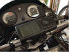
Features for the VDO C10 are:
-
Large (ish) KMPH / MPH display
-
2* Trip Counter up to 999.99 km
or miles - the second is great for road book instructions
-
Ride Time - The amount of time
you have been moving (up to 10 hours)
-
Stop Watch - Up to 10 hours
-
Average speed
-
Max Speed
-
Clock
-
Two wheel sizes
-
Small durable magnet, with
chromed case (many are plastic).
Fitting to a Classic F:
-
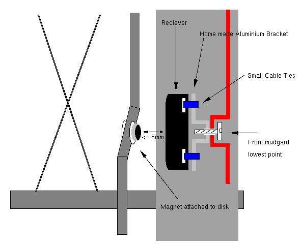
Remove the LHS front fender.
-
Work out where you are going to place both the
magnet and receiver. I used the bottom bracket on the LHS mudguard. For the
magnet, there are holes in the brake disk, you will need to attach the magnet to
one of these. work out which is closest to the future location of the receiver.
-
I used a couple of large washers, some blue LocTite
and just screwed the Magnet assembly together as tight as I dared in to one of
the holes near the centre of the disk. (don't use the holes in the outside of
the disk, the magnet will not get past the brake pads)
-
Before I attached the receiver I had to extend the
cable, I did this by soldering another length of thicker wire in the region
where it passes the steering head. ( any suggestions on how to attach, in a
waterproof manner, a thick and thin wire are welcome, my fix was trashy).
-
Measure the front wheel diameter. Test by raising
the front wheel and spinning as fast as you can. ( I manages 20kmph)
-
The wire at the right length I used cable ties and
duct tape to secure the computer cable up through the steering head and on to
the LHS handle bar. The lower half followed the brake cable.
-
Test again, and re-do the bad soldering you did
earlier.
-
Test ride to make sure nothing falls off.
On Board Computer Comments/Feedback:
-
Sigma Sport BC1400): Buying tips:
- If you are going to use it in a rally, check how many seconds it needs to
reset the trip-meter. You do not want to spend to much time resetting it.
- Brands to look at: Sigma Sport, Topek Panoram and VDO.
Fitting to a classic F:
About the soldering (nr4):
- Replace the shitty thin wires with some decent sized wire (1.5 or so).
Change the length to 130 cm. Solder it together and use Plastic Shrink Tubing
for protection against water.
- If needed get a new rare earth (= neodym) magnet and epoxy it to the brake
disc (recommended by Harl #380). Spakur in Sweden.
-
Sigma Sport Bike Computer. I have a bum
basic Sigma on one of my Hawks as there's no speedo drive with the F3 fork and
Marchi rim combo . It works great; my only gripes being the lag on hard
acceleration ( really only a concern when The Man is sighted : P ) and that it
isn't backlit . The higher end models are though I'm pretty sure , but I'm a
tightwad and it doesn't have legal headlights anyway so I just got the
cheapest option the bike shop had . Aerostich sells a neat looking unit that
is back lit and also seems to be a bit easier to operate the avg speed/fastest
speed/odometer functions. Joel.
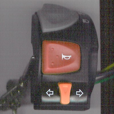
What about Installation of a Euroswitch
Peter Jensen #233 97ST VT USA
Q.
What does a Euroswitch do?
A. Allows you to turn
the lights off when YOU want to.
Q. I have MotoLights that I want to wire into my soon to be installed
Euroswitch. I want : 1st position all lights off (normal Euroswitch) 2nd
position, I want to add the headlamps and Tail Lamps to it. 3rd position all
lights including MotoLights. My Euroswitch has four wires that go directly to
the light switch part of it (eight total four are for the starter/kill). The
first position of the Euroswitch has no wires at it. The second position ( which
I believe is the parking lights) has a blue/grey and a green/black wire going to
it. The third position has a green/red and a plain green wire going to it. So
what I think I should do is cut one of the third position wires and wire it to
one of the second position wires . Then wire my lead from the MotoLights into
the wire I cut from the third position. Is that right and what (3rd pos) wire
should be cut and wired to what (2nd pos) wire ? Also could I wire the parking
lights to come on with the key and not be part of the Euroswitch. If I wanted to
do this would I cut both of the second position wires (blue/grey and a
green/black) and wire them together ? Then move the two third position wires to
the second position and then wire in my MotoLights to the third position? If the
last paragraph is correct then which third position wire in hot ? Link to the
Motolight website wiring diagram.
http://www.motolight.com/install.htm
Q.
How do I swap it over? What is the wiring sequence?
I have the Euroswitch on mine set up so in the
off position the parking lights are on, in the middle position the headlights
come on, and in the third position my driving lights come on with the
headlights. The American switch has two (2) jumpers so that the lights all come
on with the key. The Euroswitch is plug and play out of the box (off, parking,
headlights), I used a ohm meter to determine the wire which went with each of
the positions of the switch. I then reused one of the jumpers for the key on
parking lights and repositioned the headlight wires in the connector.
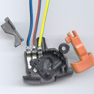
First buy a
EUROPEAN Switch from an Earlier Model Classic F650. Use a European Dealer like
Motorworks or Motobins. Remove the old switch and rewire as follows
The
description below is based on looking at the connector from the back (i.e. the
side the wires are on):
-
TOP LEFT: Gray/Blue wire
-
TOP RIGHT: Black/Red Wire
-
MIDDLE LEFT: Green Jumper connected to middle right
-
MIDDLE RIGHT: Green Wire connected to green jumper from middle left (parking
lights always on)
-
BOTTOM LEFT: Green/Black Wire (to operate headlights in position 2)
-
BOTTOM RIGHT: Black/Yellow Wire from switch (Ground Wire)
You
will have a Green/Red Wire left to connect as the wire to turn the driving
lights on (in position 3 of the switch)
My
modification consisted of:
-
Combing one of the green jumpers from the stock switch with the green wire on
the middle right position of the connector, jumping the middle two positions
together (allows parking lights to always be on).
-
Moving the Green/Black wire from the middle left to the bottom right position.
(turns on the headlights in position 2 (euro parking light position))
-
Connecting the Green/Red wire from the bottom left to stand alone (turns on
driving lights in position 3 (euro headlight position))
-
The pins can be removed from the connector by using a very small screwdriver
to press in the locking tab (look by the pins) while pulling on the wires from
the back.
Feedback:
-
When I open up the Euroswitch I can see that the three position switch has
four wires coming from it. The first position is empty, the second position
has green/black and blue/grey wires. This position is the parking lights, The
third position has red/green and green wires. So at the connector I need to
jump the green/black and blue/grey parking lights so they come on with the key
(?) Then move the two third position wires to the second position. Now I need
to find a hot wire, one of the two I just moved is hot. So I ground my black
wire from my DVM and touch the red probe to each of the connections of the
(new) second position to find which is hot. Once I know which is hot I split
it off to the third position with my Motolight wire (?) I got lights, bob's
your uncle, goodnight. XtreemLEE#1188
Signal Minders?
by Chris #856 '99F Fremont, CA
Several people asked about a follow-up on how the installation went with the
SignalMinder. This post turned out to be a bit long, but hopefully it covers how
it went, as well as most of the questions people might have. Feel free to ask
any additional questions! This is not meant to be an ad or product review. I
paid my $99 like everyone else. Sorry I don't have a digital camera, but I can
take analog pictures and get them developed, if folks are interested. (It might
take a while though...)
-
On
balance, I think the $99 price is warranted. I was really looking for running
lights, with the potential of emergency flashers. Given the signal cancelling,
as well, I feel the price was worth it for me, especially given how simple the
installation was -- even for me, a neophyte at motorcycle maintenance!
-
The
SignalMinder arrived yesterday, and it was actually easier to install than the
new headlight bulb in my 96 Dodge Stratus (which I had to do first)! The
SignalMinder really is pretty much plug & play -- assuming you have the right
unit for your bike. My 99F did take the SM-2 model with the two connectors in an
L formation. Be sure to check your bike before ordering to get the right one.
You can follow the sound, or as I did, put your finger on it to feel the
clicking vibrations.
I was also able to hook up the "running lights (marker lights) & 4-way flasher"
option fairly easily. The SignalMinder box has two ports for the microprocessor
inside, according the guy I talked to one the phone (to clarify the 4-way
flasher instructions, more on this below). I skipped the option to patch into
the brake light (which stops the digital count-down for the signal light (30
seconds = 40 flashes, there's also a setting for 15 or 45 seconds). But what I
did find out was that the two wires that needed to be patched in the front and
rear signal light wires work just fine plugged in the extra white connector
under the seat, the one that has nothing plugged into it. (People have asked
about this in the past, and the answer has always been that it's for 4-way
flashers. They really ARE!)
-
The
two wires from the SignalMinder have silver eyelets on the end. To keep these in
the white plastic connector, I added some electrical tape. They were fairly snug
without the electrical tape, but I decided to add the tape to make sure. I could
probably also get the matching white plastic connector, which I may do some day,
although my current solutions seems to work fine.
-
There's also a grounding wire, and its eyelet was a little small for the screw
already holding the other two grounding wires from elsewhere. I managed to
expand the eyelet just working the screw through, but the guy at SignalMinder
said you could clip one side of the eyelet, if that was easier. He also
confirmed that it's best to put this grounding wire together with the other two
already there. Should I want to disconnect the running lights/4-way flasher
feature, I would need to disconnect the little black plastic connector (with the
extra two wires) on the right side of the SignalMinder box. The SignalMinder box
doesn't clip to the rubber gasket vibration connector, like the old box did.
It's a lot lighter, and is not prone of problems with vibrations, according to
the SignalMinder guy. To be extra sure, I used a plastic tie-down to secure it
to the clump of wiring in the black plastic sleeve, running just underneath it.
-
Because we don't have a separate 4-way flasher switch on our bikes (or at least
on my 99F), we need to use the three dip switches on the SignalMinder box. The
first switch controls low or high setting for the running (marker) lights. The
second and third switches control when the signal (blinker) light is cancelled
(15, 30, or 45 seconds). Note: the turn signal switch on the handlebars is not
moved, but the blinker stops.
-
To
turn on the 4-way flashers, the following sequence is used: right blinker,
cancel, right blinker, cancel, right blinker, cancel. If the last cancel is
omitted, they will only flash for 4 or 5 seconds. Now interestingly, there is a
second setting if you repeat that triple sequence using the left turn signal: it
rotates the flashers left, right, left, right. I asked whether this might look a
bit like the police, and the SignalMinder guy said probably not, since the
frequency was a little faster (i.e. shorter blinks). In an emergency (like Wamer
on the Bay Bridge in an earlier post), this rotating pattern might be even more
noticeable than regular 4-way flashers.
-
There is also a disclaimer for the US & Canada, that yellow running lights on
the back of the bike may not be allowed, requiring changing to red signal light
lenses. So far, out of many, many units sold in California (mostly in LA & the
SF Bay Area), no one has needed to change to red lenses.
So to sum up, here are the pluses:
- cancels signal lights in 15, 30 or 45 seconds
- an additional wire can be connected to the brake light wire to stop the
digital count down timer (of the signal light pulses) while the brakes are on.
(I didn't do this. It didn't seem that important.)
- provides running (marker) lights in high or low intensity
- provides 4-way flashers in two patterns, all-together or alternating
- the installation was really easy, once I remembered our unused 4-way flasher
connector
Here are the minuses, as I see them now:
- turning off the running lights requires taking off the seat and disconnecting
the small black plastic connector from the SignalMinder box. Otherwise, the
running lights are always on.
- changing the high/low intensity of the running lights requires removing the
seat and flipping dip switch #1. Like on computers, these dip switches are tiny.
(For those of us over 42, we might need our reading glasses or bi-focals to do
this!) I asked about battery consumption, and the SignalMinder guy said the
battery consumption was less than a watt on high (if I recall correctly) and
even with their tail light & head light modulators (which actually don't
actually use much, if any battery power), the consumption on high is minimal.
Still it might be nice to be able to adjust this from the handlebars. Bikes with
a separate 4-way flasher switch can do this, apparently. So, I'll probably leave
my running lights on the high intensity position and see what happens with the
battery. Perhaps this would be more of an issue in colder temperatures, where
there is more stress on the battery, and more use of electric vests, etc. The
running lights also light up the left and right green "idiot" lights faintly,
which is kind of cool.
- turning on the 4-way flashers is a bit involved (again, because we don't have
the second blinker control on F650's). And, using emergency flashers without the
engine running could deplete the battery in 30 minutes or so. Still it's a nice
feature for emergencies.
-
Turn
signal cancelling device. Quasi as "winter work" I would like to tinker a turn
signal resetting for my F650GS, whereby it should be really a tidy solution.
Alternatively I would like to refer to the turn signal reminder
http://www.baas-parts.de/produkte-main-e.htm The original BMW switch must be
set manually into the state of rest, which runs off in the switch mechanically.
A connection diagram can be found under
http://faq.f650.com/GSFAQs/Photos/Documentation/Diagram-III.pdf. The given
structure makes thus the use of prefabricated systems not possibly. My solutions
are the following: 1.) One replaces the original switch by 3 push-buttons (2 x
1-pole for left/right, 1 x 2-poles for resetting). Thus one could use the
existing wiring and would have to build a new electronic. There it would
be then also a little thing to along-integrate a hazard warning flasher. The
problems are that it seems not so easy to find fitting push-buttons. Further one
would have to change a lot at the central wiring harness. 2.) One leaves the
original switch and installs a solenoid/servo under it. Associated electronics
would get its instructions of the turn signal lines as well as of movement alarm
units. The power could be got from the head-light switch. Turning off the turn
signal could take place then through impressions by means of the Servos.
http://www.geocities.com/robertosat/winker.html Robert #1071.

-
My
thumb works well and it's already attached quite well-and it's free. Runaway
#1259 (CO)
-
Used
to think a self-cancelling turn signal was the height of technological
development. Then I started riding new Triumphs and soon learned to appreciate
my thumb. My thumb does not turn off a signal mid-corner. My thumb helps me by
exercising while it presses the off position frequently, ensuring I am not
riding down the road with a turn signal stuck in a directional mode. I just got
used to manual changes. ichadwick
-
I
agree with Ian. I disabled the automatic canceller on my K75RT because it would
turn off just as I started making a turn. Guess I'm a Luddite, too. And with a
K75RT in manual mode, you get to exercise BOTH thumbs! Marty
#436-Chicago-97 F650F
-
I
have a Kisantech.com SM-2 for my pegaso, it works great, and you can make your
turn signals running lights. I'm selling my pegaso, so the unit is for sale. the
sm-2 model which fits the pegaso and f650 classic may fit other BMWs. the sm2
has two prongs on the flasher unit, oriented at 90 degrees. $70 delivered in us
cugino pegaso.
How do I
stop the Switches from Rotating on the Handlebar?
Trevor #999, Bristol, UK, 01GS
-
It
would appear that even when both *halves* of your clamp are fully tightened
the assembly still rotates.
-
If
that's the case then you need to insert a small shim between one of the halves
and the bars.
-
If
you've got no shim material to hand then you can easily cut some thin-walled
soft-drink can with scissors, (such as coke can or whatever), and make a
*shim*.
-
Don't make the shim too long or you'll have trouble getting one half of the
assembly snug against the bars.
-
Place the shim under one of the halves and retighten. If it's still loose then
keep on adding *shims* until there's a small gap between the two halves when
the screws are fully home.
-
Afterthought - I always *loosen* my left and right hand clusters on the bars,
just a little, so that in the event of a fall they twist round and don't break
the levers off.
-
I
loosen them just enough so that I can rotate the levers with a thump from my
fist, but no looser than that. We wouldn't want them flapping around in the
wind would we? :~))


