Miscellaneous Electrical Q's
FAQ
compiled
& edited by Kristian #562
Please read the Disclaimer before attempting any work in this FAQ.
What is the Capacity of the Charging System
Testing "
Ground"
Hombre Sin Nombre,
November '01
HOW do I test the Ground.?
This explanation is for the Voltage Regulator but applies to all "Ground"
Testing.
You can test your battery ground connections the same way - Take your (Digital
Volt Meter) DVM, set it for the lowest Ohm setting, often 200ohms. Put one
lead to each side of what you want to test - in this case clip one end to a good
frame ground, or the battery negative terminal (especially if you want to test
those connections also) and place/poke/connect the other test lead on the VR
ground terminal. (You are measuring across the gap, across the joint between the
VR ground terminal and the frame, right?) See what the DVM says - it should be
less than 1 ohm. Actually it should be almost the same as the reading you get
when you short the DVM test leads and get the resistance of the leads
themselves, about .2-.4ohms or so. If you get 2-3-5 ohms, or more, it's not a
good connection. I grease those connections also - the original VR frame ground
spot was a nice polished surface where the connector clamped. With my VR
questions, I tested across all my ground connections on the engine and frame
this way.
Note that the first thing to check in ALL electrical problems is the ground to the battery. The fuse pops upon hitting the starter because the starter is drawing too much juice (i.e.., too many amps, too much current). So, check the battery ground FIRST (don't just check that it "looks" like it's connected, make sure it's tight), then check all connections to and from the starter (like the solenoid connected to the positive pole of the battery) and go back from there to the handlebar switch. I'll bet good green American money that it's a very simple problem. Shank, NYC.
What is the Black Box in
the Tail Section.?
Flash #412
24-Jan-02
There SHOULD be a black box in the tail section. That is for ignition. If you
look at the wires near the tail section, there SHOULD be two blue wires, one
with red trace and one with black trace that are not connected to anything.
These are the turn signal wires that the alarm plugs into if you have one. (But
the REAL turn signal wires/connectors are in that vicinity, too.) Take a look at
the wiring diagram in the FAQ.
That SHOULD help figure out IF you still have an alarm or not.
Which sensor wire turns on the Fan and Which one the Temp Warning Light.?
Typical Problem:
Got on the bike this morning and as soon as I
switch on the 20A fuse blows. A bit of high-tech wiggling of wires and several
fuses later I have identified the problem to be with the wiring to the rear of
the thermostat cover. Thank you for the
wiring diagram Flash - not for the first time you have helped me in my hour
of need. (I think you're missing something on the horn switch, though).
My questions are (Irish F650, 1997 - has clock not temp. guage).
There are two seperate sensors on the thermostat cover, is one for the temp.
light and the other to activate the fan? Which is which? The one at the top has
a single wire, the one at the rear has two wires. Why two wires if this is a
thermal switch routing current to earth?
Answer
Oliver
Do you have a LIST of the Bulbs used on the Classic F ?
Flash #412
All of these are for F650 Funduro and ST through
Y2K, e.g.
"classic" F650's.
Light Bulbs
101 - Halogen Bulbs
by
Flash #412
About 95% or so of the power dissipated by any light bulb is in the form of HEAT. More Watts does not necessarily make for more LUMENS (photon output). Similarly, more lumens can come from a better engineered bulb of the same wattage.
There is such a critter as "color temperature." The hotter you can get the filament, the whiter the color. But there is a trade-off between very hot filaments and very long life. (Hey, if you never turn them on, they stay real cold and last darn near forever, unless you drop them of course.)
Hot filaments boil off atoms. These (generally tungsten) atoms get deposited on the inside surface of the glass envelope when the bulb is turned off and the glass cools. These deposits are why normal tungsten lamps "yellow" with age. Eventually, enough atoms boil off so as to allow the filament to open-circuit. How do we avoid this?
Fill the envelope with a halogen gas under pressure to sort of "convince" the atoms not to boil off the filament. Halogen gasses do not react with other stuff (much) at all. (They're also called Noble Gasses. I guess 'cause they only mate with their own kind or something.) Additionally, if we make the envelope out of crystal instead of glass, it can run MUCH hotter. That way, when you turn it off, the filament cools before the envelope and stray atoms are re-deposited back on the holy filament instead of the "glass." This both improves longevity and maintains that white "color" that seems to cut through darkness so well.
You don't ever want to touch a halogen bulb, hot (it'll burn ya) OR cold. Finger oils can permeate the crystal and cause premature failure. If you do, wipe the bulb with some alcohol, which is good for dissolving finger oils but won't do nasty things to the bulb.
Them new HID bubs... I dunno squat about them. But since a halogen bulb is basically a real fancy tungsten lamp, resulting in brighter, whiter, longer lasting functionality, I'm sure not going argue that there haven't been additional advances made since I quit paying attention to light bulb technology.
Disclaimer... I haven't paid attention to this stuff since H4 bubs first came out for automotive applications back in the 1970's. So it is quite possible that I misremembered some of it.
Tracing Problems Where the Fuse Blows all the Time - i.e. Testing for Shorts.
Shorts - General
Test Sequence
by Bill #1031
When fuses blow immediately, it means that the circuit in question is demanding excessive current. The demand could be due to a "short," which means that the wire conducting 12 volt power to the various appliances on that circuit is touching the frame somewhere.
OR the demand could be due to a fault in one of the appliances on that circuit. By appliances I mean electrical devices such as the horn, the head light or the fuel injection control unit.
It's a time consuming task; but once you identify from the manual which appliances are protected by the fuse that is blowing, you can go to each appliance and disconnect it from the circuit by pulling off the connector.
After disconnecting all appliances, turn on the key to get 12 volts going through the fuse (a new good fuse) to the now-disconnected appliances. If the fuse still blows, there is a short to the frame (or you have not disconnected the faulty) appliance.
After disconnecting them all turn on the key and hopefully the fuse will not blow. Then you can use an ohm meter and check the resistance of each appliance between the hot lead and ground. The one that is shorted will have a resistance of something less than one ohm.
Or if you don't have an ohm meter, reconnect each appliance and turn on the power to learn if the recently-connected appliance is the one causing the fuse to blow. This now identifies the faulty appliance and you can replace it or further investigate within to see if you can see a short to the frame inside that appliance.
If after disconnecting all the appliances, the fuse still blows, the short may be in the wiring harness. Disconnect the fuse as well as all the appliances on the circuit in question; then measure the resistance from the circuit side of the fuse to ground. You should have infinite resistance; if you have some low value of resistance, it means that you either have a short in the harness OR you have not disconnected all the appliances on the circuit.
For the Classic F see this Wiring Diagram. For the GS, maybe you can borrow a wiring diagram from your dealer. It will be helpful in tracing all the appliances that are on the circuit in question.
Shorts - Blown Ignition Fuse Cure
by Lee#1106, CT.
A month ago or so I left a thread for help finding the cause of an ignition fuse blowing repeatedly on my '00 classic. Well, it wasn't hard to find once I actually started looking (it took me a while to start looking due to the intimidation of checking every single wire and connection on the bike). It turned out that the main wire harness that sneaks by the voltage regulator had migrated itself on top of the voltage regulator. Consequently, some of the wire's insulation melted through and they were grounding out on the heat sink fins of the VR. Not Good- but a surprisingly simple repair.
After taping up each of the damaged wires I pushed the harness back to its home beside the VR. Then I noticed some features molded into the plastic area behind the VR which appeared that they were intended to hold the connectors on the harness in place. So I pushed them all down 'til they looked secure. I put the seat back on and called it a day. And the bike has been perfect ever since.
Well, today I lifted off my seat (a good month since the repair) to show a buddy where the problem occurred- and wouldn't you know it - Mr. Wire Harness migrated himself back on top of the VR again, and more wires were beginning to melt through. Darn it. Okay, I know this is a real minor thing to complain about, but I just wanted to bring it to the Gang's attention.
from Flash #412
Shorts - Blown Fuses - Feedback
The first thing to check in ALL electrical problems is the ground to the battery. The fuse pops upon hitting the starter because the starter is drawing too much juice (i.e.., too many amps, too much current). So, check the battery ground FIRST (don't just check that it "looks" like it's connected, make sure it's tight), then check all connections to and from the starter (like the solenoid connected to the positive pole of the battery) and go back from there to the handlebar switch. I'll bet good green American money that it's a very simple problem (and NOT the rectumfrier). Shank
My co-worker and I discovered that when the handlebar was turned at full lock left the fuse blew out. The cable was really tweaked that far over and she mentioned that she tended to hoist the bike around sideways when she started the bike. Thus, the culprit is a fragged electrical wire on the bars. jlee.
DC Electrical Basics - The Charging System
by Gerry #951
In answer to the Question,
how do I measure the
Power Draw of each item on the Bike, like my
Lights, my Heated Vest, my Heated Grips.?
While
everyone argues about nomenclature, I like to keep it simple. Consider this:
Use Ohm's law and it says V (voltage) = R (resistance) x I (current)
1. Voltage is simple to measure as is resistance. Place your leads across
the items being measured and have your meter on the appropriate settings for
either resistance or volts.
2. In the case of a resistor or a resistive load like a
lamp:
--------------/\/\/\/\/\/\/\/\/-----------------
Touch the probes here (marked I) so that the meter is in parallel to the circuit
being measured.
-----------|---/\/\/\/\/\/\/\/\/-----|------------
3. If your meter measures amps, it has to go in the circuit being
measured. The left end is the battery and the rest is the positive lead:
Battery
+---------------------------------------------(pos. lead)
Putting your meter in series means going between the battery and the lead where
(A) is your meter:
+-----------------(A)------------------------(pos. lead)
You have to break the circuit and put your meter in between. Also called being
in series with the circuit, or being a part of the circuit. I haven't picked up
a meter in a long time but I seem to remember that most will only handle around
5A, though that may be 10 A by now.
Measuring the amps for each item may not be necessary. Watts is simply volts x
amps. In the case of a 60W headlight and a 12-volt system, you're pulling around
5 A, in theory. Our bikes run at more than 12 volts so use something a little
higher and you'll probably measure 4.5 Amps. As the volts go up, the amps go
down. Simple.
If you pull each major subsystem and make your measurement, you'll figure out
where all that power goes. And if you're putting out more power than you're
putting in, give me a call, we're going to make a fortune with that circuit.
Feedback:
Failing
generators by nature give decreasing voltages. Rev your engine while measuring
the voltage. Using an ordinary meter might unfortunately give you a reading that
is a little bit too low as the voltage pulsates. It doesn't help drawing more
current out of the system if the voltage doesn't drop. However, the thing is
that the generator is somewhat like an old battery, the more current you tap
out, the lower the voltage will get. It's like doctors giving a blood
transfusion without stopping the bleeding. It's true that a charging system is
dimensioned differently at different bikes, but it should always be dimensioned
never to allow voltages of 14.8V or above, in fact it should stop at max 14.4V.
Many, (if not most as it's simple and cheap), voltage regulators actually work
by short circuiting the generator winding when the AC voltage reaches it's
threshold. Therefore it is not true that pulling out more current, by adding
light or whatever, will further stress the charging system, often it's the other
way around! One might think that short circuiting the generator would cause it
to burn, but:
-The generator has efficient cooling, much better than the regulator.
-The generator gets a limited EMF, (electro motorical force), induced by the
magnets.
The EMF is just slightly more than the actual maximum output power, so all
that's happens is that the engine oil gets another 400W of heat to handle, which
is negligible. RakaD
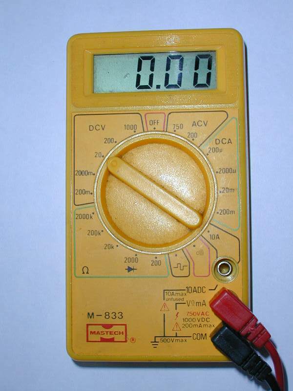
Sure, for MOST charging systems, if you pull more out of it, the voltage drops. I can say for my bike ('99 Classic), even with a full load (high beam on, brake light on, turn signal flashin', fan fannin') at idle, my output was at 14.8, and at 5K rpms, it was at 15.3, definite battery cookin' voltages. After the VR flay, I found that my Vreg and generator behaved more like "normal." Under high load, the voltage dropped (lowest it got was 13.8, plenty to charge by with no cookery). BTW, the VR flay CAN be performed without cutting any wires. I always opt for the no-surgery method whenever possible. We have a 280 watt, 20 amp charging system (in this case, we can use watts and amps interchangeably). Given: It's the voltage that cooks the battery, the more volts, the faster it cooks. Warmer weather does not help. Neither does the battery's warm locale next to the catcon/muffler. If you ride the bike with no extra draw, you may only use 180 of the 280 watts but the voltage remains the same, thereby cooking your battery. If you add accessories and are now using ALL 280 of the 280 watts available, the voltage remains the same, thereby cooking the battery. Get a digital volt meter (Radio Slack has a very nice compact one for $25, part # 22-179A). Measure the DC voltage at the battery while the bike idles (put the red lead on the positive battery pole, the black lead on the negative battery pole, ya only need to take off the seat to do this). If it is above 14.4 volts, you will cook your battery. Now rev the engine up to 5000rpms (yes, it will skittle around on the centerstand as you do this if you park on concrete), if the voltage is above 14.4, you will cook your battery. As far as I know, the ONLY way to reduce the voltage is to do the VR flay. It's not that hard, I did it and I'm a total wingnut. And I haven't had to add any water to the battery since I did it. I will state for the record that I do NOT run any extra electrical accessories save for the occasional heated grips and/or electric jacket (Gerbings) during the frigid months. Shank
A charging system is generic. The parts are bought off the shelf from about three worldwide suppliers. The variation is in how big a system the vehicle builder buys and which battery he matches it to. The choice is based on space and cost as much as function. One system has a low output alternator and can save weight by having a relatively large battery matched to it. The idea is that you start once, half flatten the battery in the process but have a long time to charge back up before the next start. Another system has a bigger alternator relative to the battery. This system flattens its battery as much on a start but then tries to charge it enough to get the next start. You can start more times in a short period. However, the battery is charging at a high rate, risking boiling. I run Hawker batteries on both my bikes and they work better than the liquid type. Andy Leeds UK #982
If your battery is more than 3 years old, you might find a newer battery a bit more tolerant of overcharging, even if the old battery is perfectly good. Batteries and charging systems are always a compromise. Do you design it for low usage and fast charging, or trickle charge for constant running. The battery either overcharges or undercharges. I have this problem with standby generator batteries - most people use them less than 1 hr a month for years until the hurricane hits, and then they run 24 hours a day for 2 months, cooking the battery. Of course the electronics manufacturer could design the voltage regulator to be much smarter, like the Battery Tender, but that would cost the manufacturer another $2 a unit in an era where 2 cents a unit is considered a significant cost difference. The idea of the GS VR on the Classic has merit if for no other reason than the GS VR's additional ground and output wires distributes load better than the Classic's minimal wiring. Since the GS has a 400watt alternator, it's hopeful the internals of the VR are heavier duty also. I can't tell you how to measure amps with your multimeter as (without special equipment) it's not straightforward, and damage to your meter is likely, and (mostly) your meter is not likely to be large enough to measure the entire load (without damage). If you really want, you can likely measure the amperage of individual components...but it's usually easier to calculate their loads. The only unknowns are the CDI and the fan. The fan wiring is easy to tap into for testing, but the CDI wiring is not as easy. Todd #389
The way I understood it at the time Flash & HsN were explaining the VR Flay FAQ, things like leaving your High Beam on and adding any accessories basically helps cook your VR and your battery, because to supply 12V to the Lights 'way-up" the front there, the VR has to (via control of the Alternator) pump out maybe 14.8 or more Volts close to the battery, which overcharges it AND fries the VR. So assuming that's correct, then putting the High Beam on will exacerbate the problem, not relieve it. Kristian #562
Like
many others, I wonder how many accessories I can turn on on my bike while
keeping the battery at full charge. Yesterday, I made the test with a voltmeter.
Now, I know that I will be OK, unless I turn on everything's. Note : I have the
Touratech twin headlight and the Xenon light.
Moto BMW F650 2001 Alternator Test - test d'alternateur
Année - Year 2001, 22000 km / 13 750 M. Engine on neutral All std equipments ON
( gauges, parking light ... )
RPM needed to hold 13.5VDC - RPM requis pour maintenir 13.5 VDC
Results:
Equipments : Watts (theoretically)
Low beam 55W X X X X X X
Low and high beam 110W X X X X X X
Heated grip low ? X X X X
Heated grip high ? X X X X
Xenon Light 35W X X X X X X
RPM : Idle Idle Idle Idle 1700 1800 1900 2000 2100 2200 13VDC / 3000 12.7VDC /
4000
Note : The Xenon light is rated 35W power consumption, as you see, it's more
than that. I made this test to know witch RPM is needed to keep the battery at
charge. The results are valid only for my bike, but they can be an indication
for others. Gilles Qc, Can GS01.
Accessory plug handles Widder Electric, vest, chaps & Gloves. Was a little bit concerned, if my 02 F650GS accessory plug 7.5 amps would handle 103 watts. Put out by Widder electric vest large size, leg chaps and gloves. I am happy to report no blown fuse on full setting, nothing but nice heat :). y2kcorvette.
The plug will handle it , but the charging system will not . Even with 400 watts, it is not adequate for ME . I have heated grips, Gerbings jacket, pants and glove and socks. I went about 150 miles last month when the temps were in the upper 30's and low 40's. About 40 miles from home I noticed the signals would not blink and the ABS dash light flashed on occasion.... I knew what was going on, so I did not shut if off---- until I got home. Needless to say, the battery was depleted. Now, if it is really cold, I use the other bike it; it has 700 watts and a w/s, if it isn't broken. Steve #1059 in MA
Don't heat the grips when you're using heated gloves. Get thermal insulated boots so you don't use the socks. Check the level (battery) frequently and top off w/distilled water (frequently). Always have a Battery Tender or equivalent on when not riding. I use a Gerbing liner w/ pants and gloves OR a Widder vest, arm AND leg chaps with the gloves and never had a problem. Art 884.
The alternator on the Classic as per the FAQ is 280W or 20 Amps. Two PIAA 1100's are 55W ea at 12V around 5 amps ea. Then the stock headlight at around 5 amp, .we're looking at 15 already +/- What is the current for the BMW heated grips on average in the low setting? (if not known will go measure). Finally how much of that current is needed to run the balance of the bike and keep the battery charged? I had a strange not so strange occurrence on the way home today...mind you all last winter I ran the bike at speed most of the time with heated vest, gloves and chaps WITHOUT any noticeable problems. Left work today and was in stop and go traffic for about a 1/2 hour WITH the PIAA's on for extra visibility for others; Not a good idea. Later on the ride home at speed. It got chilly and I threw on the heated grips on low. Then needed the horn...WHOA ! The output just was not there. Lo and behold when I got back home and checked the Voltage on the battery it was down to almost 9V! So in the nutshell if you can let me know what the stock bike draws of that 20A in normal ops that would be great. Then I can figure out how much I am over. I gotta be. But 20A you would think would be enough for the bike, the add lights and the grips...hmmmmm. Are there any thoughts for a larger alternator or mounting an additional battery source that can be charged via 110VAC after the ride?? Can the alt on the Dakar or GS be fitted to the Classic? At 480 W that is almost 40amps right?
Your alternator is rated at a nominal 280 watts/20 amps, but that's at high rpm, probably 5000 rpm or so. At idle it might not be charging at all. Short commuting and stop and go traffic is hard on battery charging to begin with - throw on 110watt driving lights and it's too much. Theoretically the entire battery capacity will only power the 110watt lights for an hour. Todd #389.
Classic Electrical Current. You can't use heated grips (on any setting) and PIAAs, no matter what the riding conditions/rpms. You can JUST BARELY run the PIAAs, but I wouldn't do it for long in stop and go. I have PIAAs and ride with a voltmeter. I ONLY use my PIAAs now when I really need them.
Past consensus from experience is that the Classic electrical system (in good condition) can support ~100 watts of accessory load indefinitely. Intermittent loads of ~150 watts are manageable if you are careful. Todd #389.
When I fought for my repair to be covered under warranty, the dealer claimed that i had probably exceeded the electrical capacity of the bike. my reply was..."PROVE IT. tell me what the bike uses to run the ignition", since that's the only variable we don't know. the service manager called me back later and said "we don't have that info. BMW doesn't provide it". He tried to get it covered under warranty, but it's a tough sell when I've got PIAAs hanging off the front. ultimately, it was denied, and I really got screwed because I'm also having to pay for the shop time to "investigate" my problem..... the work to tell me that, "yes, the VR has failed, just as you thought" is costing me more than the part. When you do the math, don't forget any of these....headlight (55/60), parking light (10), dash lights (~10-20), Fan (don't know wattage off top of my head), taillight/brakelight (5/21), Turn signals (10X2). If you have 110 watt lights, when you're sitting at a light with your turn signal, fan, and brakelight on, you're using as much as 250-270 watts, depending on the fan draw (assuming 20-40 watts). that doesn't leave much for the ignition.
I'm
adding up the total wattage consumed by the '02 Dakar, and can't find how much
the ABS uses. Anybody know? Also, to be anally retentive, how about the horn? So
far I have:
102.2 watts for all the light bulbs
110 watts for the driving lights
15 watts for heated grips (to be added)
40 watts for electric vest (to be added)
--> 400 - 267 = 133 watts remaining.
The manual provides all the different lighting demands, and it adds up to 102
watts. For example, if you hit the brakelight (21w) while the tail light is on
(5w), you get 26 watts, etc. I guess you could subtract 5w for the parking light
though . . . Turn signals add 10w, with the panel drawing a whopping 1.2 watts.
Assuming the horn and ABS have low demand, this seems like a generous power
supply; am I missing something? Or should I install a stereo and a GPS, and a
second electric vest. Scott, ID
Ignition. How'd you get 102W for the lights? Only the headlight, tail light (5w) and a few measly 2w instrument illuminators are lit all the time. The brake, TS and anything else is intermittent. From: Flash #412 (CO).
Fuel injections system (pump uses a bit I'd guess) and and computer? Coil? If you really need/want to know the available power, I'd ignore stuff like the horn, ABS, starter and other transient loads. That's what the battery is for, to answer brief loads that exceed the capacity of the system. It seems to me that to figure out the actual capacity, get a Big Ass (tm) rheostat and hook it across the battery, set to max resistance, with the bike running at say, 4500 rpm. Put your handy voltmeter across the battery as well, and crank the resistance down until the voltage reads 13.2 volts (NOT 12, you'll run out of battery fairly quickly...). Measure the resistance of the BA rheostat, apply a bit of Ohm's law, and voila, your excess capacity. Harl #380.
The ABS draws almost zero current at idle/test/monitor (less than 10W). When it becomes active, the modulators are quite heavy users. The fuse size will give you the maximum draw. Car systems can draw 150 W. The bike system shares its fuse, but it won't be that different, I'd guess at 100W, but only for the few seconds it takes to stop. Andy Leeds UK #982
Did a little test when I got home from today's trail ride: with Hi-beam, aux lights and grips turned on, I showed 11.8v at idle (1500 RPM). I advanced to 3,000 RPM, and watched the voltage bounce around for a few seconds, then stabilize at 11.9v. Advanced to 4,000 RPM: 11.9v, with no variance. So, essentially no change with RPM on my bike. I might wish it did increase a half a volt or so! So, I should ask a follow-up question: given the above voltages, do you think adding a heated vest, or a 100/55W headlight would kill my battery in short order? What IS the sensible minimum operating voltage? Scott, ID #1244
No. You should be getting over 14 volts at the battery with the engine running. 11.9 volts means that your alternator can't keep up with the electrical draw and if you keep it up your battery will go flat and there is a chance that your alternator may overheat and short out when the wire insulation melts (think Hondas and Suzukis, here). Richard #230
I rode
around the woods (both asphalt and dirt) for several hours today with my aux
lights (110 watt), heated grips on high, and vest on 3 setting. No problem. It
still starts back up just fine. I don't have a voltmeter installed yet, but I
did notice the battery tender is staying in the charging cycle longer than usual
today. But at least it had plenty of juice left to start! Razz '03 black GS,
Colorado
When considering electrical (not electronic) parts, how do the power ratings correspond? For example, how does a switch that is rated for 5 amps and 125 VAC correspond to a 12 volt direct current system? Is actually peak power that matters? Can it even be correlated?
Current is current. But AC is "self-extinguishing" in a switch. What that means is that a switch designed to switch 125VAC (at 60Hz) only needs to be able to maintain an arc of rated current for 17 milliseconds, max, before the signal "turns itself off."
Inductive loads "fight" being turned off. L*di/dt is power, too, not just V*A. So if you happen to KNOW the inductance, in Henries, of your load, you can calculate how much current will arc through the switch in 17mS to determine if you're overreaching the capacity.
The short, real world answer is... use a switch that's AC-rated for the same DC current you plan on running. If it doesn't last as long as it could or should, so what? You'll be replacing it in a year or five. So what. It might last forever. Is it worth that much of your time wondering about a $2 part?
Next time you go to Home Debit, take a CLOSE look at "standard light-switches." There are really THREE kinds. One is "T" for standard lights (tungsten). One is (either "I" or "M", I forget) for motors aka inductive loads. And the other is "F" (I seem to recall) for fluorescent bubs. Each is constructed to manage it's specific purpose. But nobody ever pays attention to which one they get anyway.
Refer also to the Battery FAQ and the The Voltage Rectifier FAQ
What about using
Circuit Breakers rather than fuses?
Q. Any reason why a circuit breaker board couldn't be used in place of a
fuse panel on a 650 or other bike? Is it cost or other reason why fuses rather
than circuit breakers are used? Seems circuit breakers would be a lot more
convenient.
How often do YOU change fuses? Go ahead and put a $4 device in place of a 25c fuse if it makes sense to you. The bike comes with spare fuses. Flash #412 (CO).
They work well. I installed a set of aircraft circuit breakers on my KLR650 about four years ago. I did an article in the Dual Sport News on the installation. They were installed so that I could reach them from my seat. I installed a set on my Dakar as soon as I bought it. Circuit breakers are more reliable and less prone to vibration and transient surges. I have worked on aircraft that had 20 year old circuit breakers in them without sign of problems. Keep in mind that circuit breakers are used in planes with sometimes over $50,000 worth of avionics installed. Contact me off-line if you want info on ordering or installation, they're very affordable and you'll never have to worry about fuses again. The reason I initially installed them was due to the fact that I had my charging system pretty maxed out, especially with the lights I had installed, and transient surges were blowing my fuses at inconvenient times, like at night, in the rain. When I installed them, I used separate breakers for charging system, lights, radiator fan, and accessory plug. I realized that when riding off-road at slow speeds, I could pull my light breaker and save my battery. Also, when working on the bike, I sometimes only need to pull the breakers rather than disconnect the battery. It works for me. Skip.
What's a Good Spray for Protecting Electrical Connections
I have been using INOX for many years on electronics, switchgear and mechanics, does not wash off easily, keeps corrosion out etc. http://www.inox-mx3.com/. Works for me! Jack, F650GS Australia.
Harl #380
The wattage of the lights you're installing is different than the stock lamps. Either match the (wattage of) stock bulbs OR as the flasher is a thermal device that works on total current flow and changes with the draw, install an electronic flasher rather than the thermal one.