F650 Voltage Rectifier FAQ
compiled & edited by Kristian #562
by Kimon, Mark #403, Chris #782, Flash #412, November 2001
Please read the Disclaimer before
attempting any work in this FAQ.
Last Updated: 31 December 2006, by Winter #1935
For other related FAQs:
Introduction
This FAQ is about the Voltage Rectifier or VR. If you were just looking
for the VR Relocation FAQ, which helps the VR Keep Cool and helps stops it
failing out in the first place, click the link to the
VR Relocation FAQ. It's one of the hardest
things to think of and one of the easiest (if not one of the more
expensive) to fix.
- Note: The upper limit of the charging system
SPECIFICATION for the F650 is 14.75 V. So much for a sealed battery's sensitive
self. And if your VR needs flaying, the battery might see 15.5 V. Flash 412
(CO).
- Note: A most useful and cheap gadget is a voltmeter.
Then you can always monitor the voltage when riding. The part no. for the VR-
(95 F650)- is: 61 31 2 346 432. This number is used on all the "Classics" from
93-00. Haakon#626. See the Aftermarket
Voltmeter FAQ.
| Note: VR Problems on Fuel Injected Models |
|---|
| Problems related to the VR on Fuel Injected Models (GS, Dakar and CS) are not known (December 2006). Classic model bikes are more likely to experience problems with the VR. However just because you have a Fuel Injected bike, does not mean you will not encounter a failed VR. |
| Why does this not happen on the FI models? On the FI models, the VR was relocated to allow more effective cooling (down to the bottom right of the engine). The VR on the of the FI models is just plain better. |
| The Best Solution! |
|---|
Okay, so you have worked out you need to fix your VR (either as a pre-emptive maintenance, or because your VR is stuffed). What solution should you use?
The best solution is to replace the Classic VR with a GS VR and relocate the VR. It may also be a good idea to replace your battery with an AGM battery too - especially if your last battery was fried by the VR.
The second best solution is to flay the VR. For this solution is is highly recommended you also replace the battery with a new AGM battery.
|
So What (Simply Explained) does The Voltage Rectifier do?
Well, it's actually shown as a combined voltage
regulator and rectifier in the
schematic.
The bike has an alternator that puts out AC, and it always runs
at full output. The VR converts that to DC, and bleeds off excess power to
maintain constant voltage. (That's why it's always so darn hot.) As opposed to
an alternator with a voltage regulator that controls exciter/field windings in
the alternator.
Generally a generator produces
for 1/2 the electric cycle while an alternator produces for the entire
cycle. i.e. an alternator has electricity flowing "both ways" while a generator
will only let electricity flow "one way" - since the production of this
electricity is done in the same means (a stator/rotor of copper/magnets rotating
within a cylinder of copper/magnets), the alternator is much more efficient
since it is grabbing "all" of the electricity being produced (i.e. when the
'north' side of the magnet runs by a loop of copper, electricity flows in 1
direction, when the 'south' side of the magnet runs by a loop of copper, it
flows in the opposite direction).
Since the systems within the bike run on DC, one of the jobs of the regulator is
to transform AC to DC with a rectifier of some sort. The other would be to
produce the constant 13.5-14 v. that we're all happy to see the alternator
"producing."
It makes sense to me (but be warned, I'm somewhat feeble minded) that the
alternator is producing more electricity at 5K rpm than it is at 1K rpm. The
regulator is the device whose responsibility it is to make sure that we see a
(relatively) constant voltage coming out of the alternator. In casual
observation of my own voltmeter, it seems like I get about 13.0 volts out of the
charging system when it's idling (and the battery is charged), and 13.5 volts
when I'm running around with higher RPMs. Seacuke, #1214, F650GS, California,
There are two types of Alternator:
(1) The constant magnet. Here a
magnet turns inside a set of charging coils. The output is rpm related, up to a
max. When the output is more than what is "used" and the battery can "consume",
the rest is shorted (to "earth" -the frame). A total waste of energy, but cheap
to build. That is what the F650 has.
(2) The other alternator type has an
electro magnet turning inside the charging coils. Here the charge is controlled
by the "power" applied to the magnets. That is what all cars and some other
bikes have. (All BMW boxers have this type)
Both of these generators need a rectifier to convert the AC to DC.
A generator also has electro magnets turning inside a set of charging coils but
here the output is DC. This design was used at a time when rectifiers was
expensive and unable to handle large outputs. The generator output is much more
RPM dependent. The alternator can produce a lot more power at low rpm`s than a
generator of the same physical size.
Haakon#626 (Norway,12-1999- F650GS)
The VOLTS available from our permanent magnet
alternators don't go up with RPM, in fact, if you have lights on and a bunch
of electric clothing hooked up, the voltage might even go DOWN at higher rpm.
Why? Because the power demand that the IGNITION places on the system varies
directly with rpm. Cheap to produce. (Great for the manufacturer.) Burns up VR's
now and then. (That 's the customer's problem once the warranty period is up.)
Flash#412
See also
Electrical Misc FAQs - DC
Electrical Basics, particularly for feedback on Power Draw
If you want some more detailed information
see Electrex Site, which now has new
tech info pages.
We have the charging system described in Figure 1.
Here's a summary of Electrex information, chopped and
edited from applying to VFR charging circuits to apply to us. Of special
interest is paragraph 3 and 4, as to why some particular bikes are prone to
failure. (Not good news I'm afraid.) The electrical troubleshooting chart on
their page gives some expected outputs for the AC parts of the alternator coils.
| Voltage Rectifier / Regulator Operation |
|---|
This link s to a very nice schematic and theory of operation for the VR of a Suz*k* GS400E, which I believe is interchangeable with the one in the Classic (except for connectors).
Pay special attention to the last two paragraphs. THAT is why we have the VR flay. The flay essentially connects the "Monitor" input to the "Battery" output via a relay that is activated by the ignition switch. The reason is that the "monitor" input is returned via several connectors and contacts inside the ignition switch. This causes a voltage drop back at the VR which fools the VR into raising the output to an artifically high level (which then boils the battery).
I suppose if your VR fried and you're handy with a soldering iron, you could build your own replacement following this schematic. Flash 412 (CO)
|
VRF Regulator Rectifier Basics
Inside there is a six diode full wave rectifier, and
every phase input can be switched to ground through a thyristor. The thyristors
are switched by a regulator circuit that measures the DC output voltage. We call
this a shunting regulator. It is a very simple system, and doesn't work very
efficiently. But it does the job while not dissipating too much heat. That is
why most OEM manufacturers still use this setup.
First of all the regulator relies on it's heatsink. That in itself is not bad
, as long as there is good thermal contact between the diodes and thyristors
inside the unit to the housing, and as long as there is a good airflow.
Quite often when a regulator/rectifier fails, a new one
will fail after a fairly short time. It is a recurring problem (not on all
bikes, but has been seen quite often). The stator has 18 poles, 6 per phase.
Each pole has (I don't know exactly) about 20 turns of copper wire on it.
Between the phase outputs of a delta wound system you will have 120 turns.
Because of the hot spot in the engine, the copper winding's insulation starts to
fail after some time. Most likely that will be somewhere from one layer of
windings to the next layer on a pole. This usually happens only under load and
when the unit is hot. Imagine a few of these shorts in between the phase
outputs. You will have not 120 turns but say 50 or 60. The complete charging
system will still be able to reach 14.4 V DC, it is rated for about 400W.
When you have a transformer with only a few thick windings, you will get a low
voltage but higher current output. The same happens in the VFR Delta stator.
Those 60 turns will give a much lower Vac but a much higher Iac. And diodes in
regulator/rectifiers don't like high currents. If they are rated for 35 Amps, as
most diodes are in this application, they can handle that whenever they get
sufficient cooling.
When they run hot, the max current they can handle drops
down quite a bit, which makes dissipate even more heat, and finally one of the
diodes fails! Electrex stators are wound in star. The total power output is
about the same as the original (lower Iac times higher Vac makes about the
same... I know this is simplified, there is more to it....). But there are
always two phases in between the phase connections. (=240 turns) The Vac is
higher, and the Iac is lower. Even if there would be a short in between some
layers of turns (I haven't seen that happen) you still wouldn't have the current
output of the original stator, which is what destroys regulator diodes.
So far this is still unproven, but seems correct. It is difficult to prove, as
you need to check the original stator for shorted windings whenever the systems
is under load, and very hot. And it doesn't need to do it all the time even!
Bikes that have had a few failing RR's stopped frying them after replacing the
stator.
One last thing:
Problem #3:The output of the Voltage Regulator/Rectifier (VRR) is fed through
the wiring loom and some sort of junction box to the battery. Make sure you have
perfect connections here. I found a number of problems with voltage drops over
these lines. Check the fault finding chart on
http://www.electrexusa.com. It will
guide you through the process. The best thing to do, if you see any voltage
drops in between the VRR and battery (we are talking high current here, so any
bad connection will give a significant voltage drop) is to feed the output of
the VRR straight to the battery terminals using a (good quality) inline fuse.
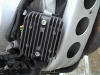
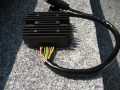
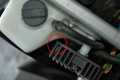
Where is it and What does it look like?
On the Classic, It's located
here under your seat, is a grey 2 x 2 square aluminium-looking device with
a bunch of fins on top and a heap of wires coming out from underneath it.
MAKE SURE ALL THE WIRES ARE KEPT WELL AWAY FROM IT: WHY? It
gets HOT. See the
Electrical Misc FAQs - Tracing Problems Where the Fuse Blows all the Time.
Is there another name for this thing?
It is often (incorrectly) termed a Voltage Regulator which is partly
true because it DOES regulate the Voltage, but also rectifies it. It's
also actually shown as a combined voltage regulator and rectifier in the
schematic. The bike has an
alternator that puts out AC, and it always runs
at full output. The VR converts that to DC, and bleeds off excess power to
maintain constant voltage. (That's why it's always so hot.) As opposed to an
alternator with a voltage regulator that controls exciter/field windings in the
alternator. Flash aptly calls it a rectumfrier, because it gets so darn hot,
which is why he suggests to move it. See the
VR Relocation FAQ.
Failure and Testing
What are the symptoms of it failing?
- The Hard Starting / Poor Running FAQ can help identify all sorts of problems with your bike, some of which may or may not be related to a failing VR.
- (Particularly when the bike is cold) The bike starts but after about 15 seconds the engine splutters as if lacking fuel
- The bike typically will not rev beyond 2500RPM until warmed up (this can include an excessively long warm-up time)
- You may find the engine splutters above 4000-4500RPM
- Battery low on water (caused by the VR overcharging it)
- Battery low on water (the battery could be killing the VR)
- Tendancy to blow headlight globes, and when they have blown, misfiring increases
- Bad misfiring and powerloss above idle
- Symptoms are reduced by turning on the lights, heated grips etc.
- Yellow wires between VR and alternator damaged / fried
- Voltage spikes to over 15V with the bike running (see testing section)
- Voltage way below normal when the bike is running (see testing section)
- My VR failed in a unique manner. The bike would start just fine and the VR
would bring the battery back up and then turn off. The problem was that the VR
would never turn back ON without turning the key off/on. This was fine during
the daily commute but maddening when going on an extended ride on the weekend.
I finally figured it out by hooking up a voltmeter during a ride. I've kept
the duff VR as a spare since it IS good, as long as the user is aware that one
must power-cycle it every so often at the risk of discharging the battery.
Point is, at no time did the battery ever read high with this type of VR
failure. I'll hazard a guess that my VR failed because the dealer (in France)
applied the hot side of an anti-theft device to a point where the aftermarket
(French) schematic says, ~"Attach no wires here!" I suspect that the relay
coil of the anti-theft had no freewheeling diode and took out some diode or
summat in the VR. Hence the AFTERMARKET warning. The P.O. never noticed the
problem as he never took the bike on any long rides without stopping every
hour or so. First of all, the alternator runs WFO all the time. This means
that the higher the RPM, the more electricity is needed to generate SPARKS, so
the "excess" is lower. Next... the next time you are riding and notice the
voltage start to DROP, turn off the key for a second and turn it back on. If
the voltage jumps back up, your regulator is failing the same way mine once
did. It would charge the battery just fine when you started the bike, right up
until the VR decided not to charge it anymore. Then, it would NEVER come back
on unless you turned the ignition off and back on. In other words, it was FINE
for my commute all week long but the bike would DIE when I went for a ride in
the mountains until I figgered it out, and then replaced the VR. Flash 412 (CO)
So How do I test it?
- For Best Results, make sure the bike is good and hot. Don't
check it cold. You will need a Voltmeter, which you can buy from your local electronics store.
- The Voltmeter photo shows a setting of 20V. Depending on your voltmeter, depends on if this is what you require. If you are unsure what setting to use, start at the highest setting, and work your way down (in this case 1000 volts, then 200 volts ...)
- Start the bike and make sure it is good and warmed up. Heat can affect your results, so make sure you measure the voltage not just once the bike is warmed up, but try measuring it after 30 minutes of riding if you can.
- Either attach the probes to the battery, or get a helper to hold the voltmeter probes to the battery.
- Rev the engine to 3000-4000RPM.
- The voltmeter should read about 13.8 to 14.5V
| Volts @ 3-4K RPM |
Test Outcome |
|---|
| Less than 12.0V |
VR is dead - under charging |
| Less than 13.8V |
VR probably dead - under charging |
| Between 13.8V and 15.0V |
VR most likely okay |
| Above 15.0V |
VR most likely dying or dead |
| Above 17.0V |
VR is dead |
Normal VR Test Results
| Rider
| Bike Off
| @ Idle
| Few mins @ Idle
| > 2500rpm
| Comments
|
|---|
| Ike647
| 12.1V
| 13.0V @ 1100
| 14.1V @ 1100
| Rises to 15.0V @ 2500
Drops to 14.1V after 45secs
| Bike sitting for 5 days
|
| Chris #782
| 12.6V
| 14.4V @ 1700
| 14.75V @ 1250
14.96V (with lights)
14.50V (lights+horn)
| 13.80V @ 3000
14.85V (lights) @ 4000+
| New battery, freshly trickle charged
|
| Harl #380
| ?
| ?
| ?
| 14.18V @ 3000
14.34V (no headlight globe)
14.34V (headlight pluged in)
| 14.18V after stopping motor
|
| Colorado Bob #1297
| 12.98V
| ?
| Idle Speed: 1500
15.5V (fan on)
15.13V (fan+high beams)
14.8V
14.93V (high beams)
| RPM: 3200
15.02V (fan+high beams+brakes)
14.9V (fan+brake lights)
14.88V (fan+low grips)
14.95V (fan+high grips)
14.58V (low grips)
14.6V (high grips)
| Engine warm to start
14.5V dropping to 13.3V within
5mins after turning bike off
|
| Kristian #562
| 12.37V
| 12.13V (no headlight)
| 13.56V @ 1550
14.20V @ 2mins
14.62V (lights on)
| 14.19V @ 2000
14.25V @ 2500
14.26V @ 3000
14.30V @ 3500
14.33V @ 4000
| Bike sitting at work for 4 hours
Drops to ~9.00V when starting
Fan came on @ 2500 due to heat
|
Kristian #562
(2000 model GS)
| 12.72V
| ?
| ~13.60V
| 14.08V @ 2500
14.09V @ 3000
14.07V @ 3500
14.06V @ 4000
14.06V @ 4500
|
|
| Todd #389 Comments |
|---|
Just comments for future reference: I've been riding around
with the VR completely disconnected, both plugs, just on battery power on my
slightly injured battery.
After charging it fully, and making a start (bike always
starts as fast as I can remove my finger from the button), the voltage is
remarkably steady.
The CDI must use considerably less than 1 amp.
Running the bike for 1.5 hours my load voltage with
ignition running (with bike running) only dropped from 12.5 to 12.3 volts. (No
headlight and only a few minutes with running lights (I have the Euro switch),
modest brake light use, and a couple of minutes of radiator fan use.)
After stopping the bike and restarting it 4 times, the
battery was recovering while running and the voltage was above 12.2 volts and
rising.
Still get the same (acceptable) test readings (both BMW and Electrex test specs)
off the stator, even when tested quite hot.
The voltage was quite steady as long as the radiator fan (or headlight, running
lights) wasn't on.
The fan is a serious drain. Not sure what voltage the CDI
quits at, maybe 11.2-11.5 volts?, but if you were running on the open highway,
you could run a long time, maybe all day and charge at night.
Obviously this experiment does not apply to the FI or ABS models.
Sure makes it hard to tear it apart for rewiring when it still runs so well -
except in traffic (it's like 95 degrees here every day).
|
| Mark #403 Comments |
|---|
|
If what is being said is true, about 14.8 vs. 15.3, maybe
that's why some people are having to add water a lot, and others, like me almost
never have to add water.
My regulator runs at about 14.3v most of the time, can jump
up to 14.8. but never sees 15v. maybe there's a quality control problem with the
rectumfiers.
I did confirm what someone else said. A GPS reads about 0.4V lower than correct.
It was explained as being due to the diode, but I don't know what the hell that
means...nonetheless, I confirmed it.
The voltage meter reads higher. also, the Garmin III+ is
somewhat inaccurate, in that it isn't consistently 0.4V under, but floats
between 0.3-0.5V under.
|
| Kristian #562 - '00 GS Comments |
|---|
|
Used my own patented in-the-FAQ-already Middle Section Faux-Tank off procedure.
Took some photos for proof. You owe me a few beers.
I found the info on the accuracy of my Digital Multimeter. For DC Voltage it is:
+-(0.5% of rdg + 2 digits). And it reads in hundredths. So, if it read 15 volts, then it could actually be from 14.95 to 15.09 if my math is correct. 1999 BMW F650-SE.
|
Why does the voltage creep up after first starting?
- When I first start my bike, the voltage pops up
to around 13.0-13.5 volts or so, then slowly crawls up to 14.0 volts. Why does
the voltage creep like that? It seems independent of the RPMs the motor is
turning, rather it's a time thing - usually takes from 5 minutes to 10 minutes
to get to a solid 14.0 reading.
- It is because the battery finishes absorbing a
significant amount of the voltage of the system when it re-charges from the
starting drainage Flash 412 (CO)
Is a high AC voltage good for the bike?
- The DCV measures today 14.3-14.4V, which I think
is good (I have flayed the VR before). However I also measured the ACV, which
was about 30V. This can't be good for the battery can it? or is just my
measurement that are incorrect? All comments would be very much appreciated on
this subject, since I am a little confused over this.
- The basic equation
is P=IE, where P = Power (Watts), I = current (Amps), and E = Electromotive
Force (volts).
The voltage regulator performs two tasks:
1) It changes the alternating current to direct current probably with diode
bridge.
2) It decreases the voltage to a steady 12V.
It seems crazy that the VR would be given 80 volts (at idle!) to futz with, but
I haven't measured it myself. But then again, if our (GS) alternator is 400
watts, 80volts would mean 5 amps, which sounds about right. And actually, my
interest is really piqued at this point. The numbers do work out, 14.5 * 27.5 =
398.75 watts, which is (approximately) the same as the 80v@5A. But the wildcard
(to my weak mind at least) is what component increases current at the expense of
voltage? I should remember this, but I don't. My days of being in school where
we got to mess with such components are long behind me I'm afraid. Seacuke#1214
- Here is a little
tutorial from Electrex on our
charging system.
The charging system of the F650 CLASSIC is like the picture called "permanent
magnet generator FIG 2." (The VR flay moves the regulator wire back from the
other side of the switch to the positive battery terminal via a relay.) Note the
note in bold print that says that to measure the AC voltage, you must measure
between phases and not to ground. Measuring between one phase and ground gives a
measurement that doubles the actual AC voltage value. The IGNITION COIL is in
fact a transformer. It turns an amp or so of ~12V DC into a brief spark of a
milliamp or so at ~15-20kV. Flash 412 (CO)
- Flash's "charging
system" link was very interesting. If I understand the information, I think it
is the VR that converts the 80 volts/5 amps to the 14.5 volts/27.5 amp output,
so that the bike's electrical system has current that it can use without melting
something or blowing up bulbs. Any current that the bike does not need to draw
gets dumped into the VR housing and is converted to heat (hopefully not too
much), just like a bread toaster. Richard #230
- Richard stated
above that the Classic's available current was something around 19.3 amps. This
multiplied by our 14.5 volt value yields 279.85 watts, which is correct.
Seacuke#1214
So what does turn 80 volts/whatever into 14.5 volts/whatever,
if it is not the Voltage Regulator/Rectifier?
- MATHEMATICS. 80
volts is NOT 80 volts. It is 80 volts, measured improperly at a single phase of
three phase AC. It is probably 40 volts, though I suspect less. But phase
voltage is horseshit. What matters is LINE voltage. Rectify the line voltage.
Now do it twice more for the other two lines. Now add them up and use the proper
multiplication/division factors for three AC phases rectified into DC. NOW you
probably have a rippling wave with about 15v at the troughs and god knows what
at the peaks. The rectifier chops off everything over 14.5 volts or so and turns
it into heat. The peaks are NOT 80 Volts. Proper measurement techniques and the
mathematics of the conversion of three AC phases to DC knock that number WAY
down before it ever gets to the VR. The VR just fixes what's left after the
magic of science is done.
The only way that I have taken my measurements is across the battery
terminals. When my VFR VR failed, I measured 20 volts at idle across the battery
terminals. I am not sure what kind of voltage I was measuring, but it was
definitely voltage that got past the VR. Richard #230: 1997 Funduro
The 20 volts you measure with a KNOWN-BAD VOLTAGE REGULATOR means NOTHING when
assessing the operation of a PROPERLY functioning system. Basically, you have no
idea at all what you were measuring if you had the meter set to DC and your VR
was fried... Is your meter analog or digital? What is the impedance of the
meter? What is the frequency roll-off of the meter?
How the THREE PHASE AC BECOMES 12V DC. If you looked at it on an oscilloscope,
there is no telling what the ACTUAL waveform would have looked like, never mind
what your meter displays the voltage value to be. If the bike was idling at 1500
rpm when you slapped your meter on it, you'd have a 9kHz pulse-DC wave (three
phases per revolution, full-wave rectified) with low and high values of... who
knows? There is no telling what your meter would done with such a wave before
moving the needle or flipping the bits to display some value.
Electronics measuring instruments are generally quite a bit more complicated
than micrometers. Micrometers don't lie (unless you don't know how to read
them). Electronics instruments require some skill and training to KNOW when they
may be lying. Your "20 volts" number means absolutely nothing. You may as well
have written "20" on a piece of paper and tied it with two bits of string to
your battery terminals for all the REAL information you gleaned from the
"measurement" you made on charging system running a defective regulator.
Saturday I helped a friend fix her KLR650. The headlight and tail light were not
working. She thought the glass fuses looked good. One looked sort of "Smokey" to
me. She put a meter across the fuse in the circuit and when it showed 0.8 ohms
she said, "See, it's good." I pulled one end of the fuse loose and lo and
behold... the fuse was indeed open. A new fuse fixed her lights. In her case,
the meter was measuring the system, not the fuse. In your case... you were using
a DC instrument to measure a complex waveform. If you get around 13-14.5V at the
battery with the motor running, things are fine. The question I thought you were
asking pertained to what happened to the 80 volts "measured" elsewhere.
Flash #412
Fixing the VR
Is there an aftermarket source for this Rectifier?
by HsN
Our VR problems are no worse than most (Nippondenso VR equipped) bikes. So of course there must be aftermarket RR's available, which there is. Note that this ours is a COMPLETELY different system than the R and K bikes. On the Honda VFR sites, the VR failure is common enough that one of the sites has a remarkably thorough survey form at:
http://www.troutman.org/vfr/rrsurvey/ and the best summary of Honda VFR
VR problems, much of which applies to the F650 can be found here:
http://www.yft.org/tex_vfr/tech/rr-maintenance.htm.
I think most of the internals of most of the (3 phase permanent
magnet) VR's are similar, it's just a matter of a few details, like the capacity
(amperage) and the connector plugs. (Obviously, there's a GREAT difference
between the positive green voltage sensing wire of the OEM Classic VR and the
negative green wires of the of the GS VR. As in Bzap!) At one time I would have
believed it was mostly the connectors, but now that I realize the Electrex
doesn't come with any, that's a moot point.
Electrex
- Interestingly
http://www.electrexusa.com/ now offers a VR (they call it an RR) for the
F650
http://www.electrexusa.com/bmw.htm, and also a replacement stator. (There
is a different model VR (and no stator) for the 650 Pegaso
http://www.electrexusa.com/aprilia.htm.). The Model number specified on
their site is the RR18*. The Asterix means that the connector is
different. If you look at
http://www.electrexusa.com/rrlist.htm, it does not list F650 for the RR18.
The man who answered the phone told me that they now offer the RR71 as
the DIRECT replacement (with the proper connector already installed). Since
the RR18 says it is for Honda CB250/400N, CM250/400, FT500, Flash
decided to ask what the RR71 fits. The man said... ANY regulator
rectifier that has three yellow wires, one positive and one ground would work
just fine, like for any Kawasaki or GS (assume he means Suckzuki) or really
anything, as long as it isn't like a hundred cc's which in that case it
wouldn't handle the power. It is $118 from these guys, so looks like if your
VR dies in Pull Pizzle, Oklahoma, the local bike graveyard will be just what
Herr Doktor ordered.
- They claim it's superior to the
factory unit, and cheaper, but no prices are given. They offer some comments
on why some of the 3 phase regulators fail, and a circuit diagram or two. At
the bottom of the page they have a link to the (Suzuki)
GS Resources where they discuss
several problems with the bike including common electrical problems such as VR/RR
failure and stator meltdown. You can find more information on this in the link
http://www.gsresources.com/gs_watchout.htm where they also discuss 3 phase
VR failures. Since OUR F650 VR is made by Nippondenso, I'd suspect we're
talking tomAto vs. tomAHto here, probably the same VR with a different plug. I
haven't heard of F650 stator meltdowns yet, but it's something to keep in
mind. It would sure be interesting to see what Mr. Electrex had to say if
someone (like a REAL EE) had the time to start a dialog.
- You may want to check out this site
for feedback on Electrex. The old Suzuki GS bikes were bullet-proof but with
dreadful electrics, and the fix of choice seems to be the Electrex products.
You will notice that the site is sponsored by Electrex, but I'm pretty certain
that happened after a lot of good experiences with their products.
http://www.thegsresources.com and
http://www.thegsresources.com/garage/gs_statorfacts.htm
Mason #631.
SX Electronics
I found that these guys in Greece actually make a Regulator for the F650,
the "SX7 80" for 80 Euros.
They use the same regulator on the:
- Suzuki BANDIT 250/400 SX7 80 and the
- Suzuki LS 650 SAVAGE SX7 80
However none of the Hondas, including the CB400 Four, use the SZ7 Model.
I suspect that most of the time when the websites say "minor
modification is required" they are talking about changing connector plugs.
An interesting comment clipped from the SXelectronics.gr website:
According to the widely adopted design of similar products, the alternator
works always in full power so the engine has always the load of the full
powered
alternator. The regulator rectifier we manufacture, operates in such a way that
only the current needs of power are loading the alternator, so
there is
no extra power drawn from the engine. Other benefits our products offer, are the
low operating temperature of the regulator rectifier and a
small increase in the power of the engine.
My comment - this sounds interesting, a VR with a different internal design.
I believe our regulator is the shunt type - always on full, bleeding power
off as needed to a resistor where it dissipates as heat. As opposed to a
switching VR (the SXelectronics type), where the VR just switches off the
power when it's not needed. (If the VR switches off the alternator input to the rectifier wouldn't it run MUCH cooler than if it switches off the
rectifier output (DC) into the VR?). Either way, the circuitry is more complex
than in the OEM VR. HsN
Off Another Bike?
In a 2002 Sprockets Chris & Erin Ratay wrote: "FYI: We
confirmed we can use a regulator from a Honda CB400 -- it is exactly the same
shape, with mounting holes in exactly the same places, and 6 wires. Price for
BMW part here is probably around $125, the Honda part is US$55. The only diff
is the color of wiring - 4 wires are the same: 3 yellow, 1 red-white; for use on
BMW, need to swap positions of the brown (earth) and green wires - Honda uses
green for earth."
Note that Erin & Chris did NOT actually change to that regulator.
Their problem lay elsewhere.
I did some research on this subject because
you have to ask the question "Well,
the wiring, VR size etc may all look OK from the outside,
but is what is
inside the
VR up to the 280W output of the F650 alternator?
So, you have to check the Capacity of the Charging System of the bike it comes
off
Here's the results of that Search, in the CB400
Rectifier FAQ.
Has anyone actually USED another VR or Stator?
Electrex
Hombre sin Nombre has. Here's what he's go to say
about it:
After installing $307 dollars of Electrex parts, I had the
joy of noticing the dreaded dashboard cluster crack. There's a crack starting in
the lens of the idiot light cluster, bottom right hand corner. It continues into
(and is probably caused by) a larger crack in the black plastic dashboard
itself. POS is 3 months out of warranty, and I keep the bike inside the house,
rarely park in direct sun, never splashed it with gas. Check out the bottom
right corner of your idiot lights and the nearby dash with a light you can hold
at an angle.
Continual problems like this (and the receding valves) make me consider finding
a different bike, one that I might keep longer and have fewer problems with, but
that I might find parts for 10 years from now. I have no idea what bike that
might be. Right now there are few bikes that suit my purpose and interest me,
and even fewer locally available choices.
I figure I'd share a couple late comments FYI that might be of interest on the
Electrex stuff - I have not yet energized it, tho' I hope to tomorrow. I have a
fairly complete chart of test values on the new VR if you want me to work it up
into something readable sometime. (Also from a KLR Test Manual, with an
alternator and VR similar to ours.)
Electrex isn't in any hurry to ship anything, they didn't Insure, and they don't
pack except to throw it loose in a cardboard box. For the price, at first glance
I was disappointed in the products. The connection wires on both units seemed of
poor quality, certainly no better than OEM. (While unmarked as such, turns out
they might actually have 105C rated insulation.) Both bags are marked "Made in
Europe".
The stator was discoloured with a slight patina of rust, despite being in a heat
sealed bag. It also showed evidence of having been dropped several times, with
several impact cracks in the (thin with lot's of pinholes) epoxy coating on the
coils and chips in the epoxy and varnish covering the laminated plates of the
ferrous core. Not nearly as good looking (wraps, epoxy, and insulation) as OEM -
looks like another product of Bulgaria.
Sloppily made, it's hard to push into place. I did my prep
to the bolt holes, flattened most of the large lumps of varnish on the mating
surface, and pulled it into place with it's mounting bolts. (Then removed the
bolts and did the Loctite and torque thing.) You'll have to shorten the woven
insulation sheath without nicking the wires, and the wires themselves are a foot
shorter than OEM - no slack in the new installation. But they do include some
plastic sheathing, and a new plastic plug and not too horrible brass terminals
in order to match the plug in the bikes harness. The stator was within 2 bags.
The inner one had it's tag cut off - the remnant says ..."within the EEC." But
the good news is that the outer bag for the G07 stator lists: Honda VT500 Ascot,
VT600 Shadow, VLX600 and Yamaha XV535 Virago, XZ550, XV700/750 TDM850, XV1000
Virago, XV1100 (no F650 listed). So it would suggest that with a little
attention to detail, stators from these bikes should fit our Rotax, as might
their voltage regulators. The Electrex stator might be one gauge lighter wire
than the OEM - assuming more windings per coil, that might indicate higher
output voltage, with lower amperage.
The VR comes with bare wires and no terminals - I guess they figure by the time
you're looking at saving 20% off OEM prices you've long since burned off your
original terminals and have installed your own, so you can solder on whatever to
match. It has no markings on the bag except BMW F650 1997-00. Note that it
doesn't say 1993-96? Maybe it was packaged for the USA. It's similar in size,
heavier fins, but the cross section for the bolt holes is thicker, so longer
bolts than the OEM bolts are needed to mount it. Otherwise, it will mount in the
same holes as OEM. Between the bolt holes and the terminals, some prep needs to
take place before it can be installed on the side of the highway.
The Stator wires are unfortunately a foot shorter than OEM
- no slack in the new installation. But it's just long enough, if you route it
touching the carburettor bowl (a big no-no for wires running 75 volts that have
a tendency to melt) and shift the entire wiring harness forward 2-3 inches. And
I have slightly longer (1-2")harness wires to the plug, since I replaced all
mine when I burnt the first VR. Little did I know that I'd later wish for 6" of
slack. The alternator plug used to sit on top of my battery - now it sits
underneath and in front of the battery vent - not the best place for open plugs.
And speaking of plugs, the plastic plug was not the exact mate to the other OEM
plug. Easily adaptable.
Sure hope it gives me lower voltages!
Don't be in any hurry to buy Electrex stuff - after only
being installed a month/800 miles, while sitting in traffic, the Electrex VR
overheated and exploded, coating the seat/fender/burp tank and intake snorkel
with burnt epoxy, melted rubber lava, and oily slag. (At this point, the bike
lost it's ability to idle also - might just have been low voltage.) Never had
one fail that badly before. At least it didn't melt the side cover or burp tank.
I haven't done any diagnostics yet, as it took me 2 hours to dissemble and clean
the mess enough to bring it inside, as the burnt stench is too sickening to have
on the porch. (I don't mind the mess, but the stench is nasty, and it sprayed
and dripped everywhere.)
Because of the 4 hour time difference, I was able to call Electrex. They have no
idea how to handle a warranty claim, suggesting that I might mail it back, and
they'll examine it, but maybe I should talk to their head technician (Ritzo) who
wasn't available, and who did not return my call in 4 hours. No hurry, because
they have no more VR's in stock, on backorder with unknown delivery date.
("Business is so good, we just cannot keep inventory in stock, it goes out as
fast as it comes in, but we'll put you on the list for later if we get some.")
Looks like AT LEAST another 3 weeks, IF I'm really lucky.
This will mean that for 2002 my bike will have been down 3 full months waiting
for parts. My next bike will be JAPANESE. Might not have style, but at least it
will run. I've had 2 strokes that were more reliable.
When the VR first blew, while stopped in traffic, all I
noticed was that the bike started to smell funny. After a few minutes, I lost my
idle, it dropped to about 900rpm, but the bike ran fine and restarted OK. At
first I thought that I had blown a head gasket, and was burning
coolant/antifreeze. But the coolant and oil are OK, and I discovered the VR
mess. Then I figured the idle changed because I was riding on a dying battery,
badly discharged by riding with a dead VR. But today while testing, with the VR
removed, battery full charged, bike starts right up, but the idle is still way
too low. Nothing in the air cleaner, plug caps and coils have proper resistance.
I'm digging thru things but I'm clueless why the VR incident would affect the
idle. I'm finding no wiring problems, no loose connectors or battery terminals.
The idle has always been very constant - I've only adjusted it once in the last
15k miles. I was riding without a VR for a couple weeks, 200-300 miles, a while
back, and that had no effect on the idle whatsoever, nor would I expect it to.
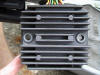
Can I use a GS Voltage Regulator on the Classic?
GS VR - The Size of it
- Well, it will certainly handle the Output of the Alternator
because the GS has a 400 Watt System and the Classic only 280W.
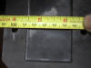
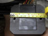
So the Question is will it fit? The dimensions are shown in
the TITLE of the Pictures.
-

- The answer is YES it fits, and it works. The only thing you
need to worry about is the wiring.
GS VR - The GS Wiring:
- This
Diagram LOOKS incorrect, as least as far as wire colors go, compared
to what is ACTUALLY observed on the bike. The schematic only shows 3
yellow (alternator), 2 brown (ground) and 2 red (output) wires on the VR.
The schematic Diagram shows both VR red wires direct to battery positive,
and both brown wires direct to battery negative.
On The GS VR:
- Ritzo at Electrex
says he just got to look at my old VR (despite the fact that I know it was
delivered to them at 2pm 11/12, and confirmed it by phone) but has no
conclusions or recommendations yet, but he'll call me back (that was 2 days
ago).... supposedly they have 2 new F650 VR's coming in "tomorrow", one of which
will be on it's way to me "the same day". Last time it took them 9 days from
"same day", so in the meantime I'm looking at modifying the GS VR to the
Classic, in the least destructive way possible, so that I can also reinstall the
Electrex VR painlessly.
- Got my used
second-hand 01' GS VR today. I can confirm that the wire colors on the VR are
R/W, Green, and Yellow, and NOT the Red and Brown and Yellow as shown in the
factory schematic.
- Inspecting the VR, there are 7 wires.
it goes: Yellow, Red with white stripe, Green, Yellow, Green, Red with White
stripe, Yellow No Brown Wires.
- And those are NOT the colors shown in the "Diagram V" schematic, unless I'm
completely missing something. The schematic shows red, brown, and yellow.
Obviously red = red/white, and I assume somehow brown = green, but it seems
unusual the colors don't match.
- The above photos shows at least one green wire, so the question is, "Is the
schematic incomplete"? Just what color are those wires on the GS VR?
- The substitutions
seem obvious, but in terms of shelling out $200 to adapt the (no warranty, no
return) GS VR to my system - if the schematic colors are wrong, is the wiring
different also? NO voltage sensing wire for the VR? Just inputs (yellow),
outputs (red) and grounds (green/brown)?
- Any chance it's
obvious what those (r/w and green) wires connect to on the bike? Like if one of
the green wires goes straight to ground? OR is the VR mount to the frame THE
ground, and the green wires are both voltage sensors? If so, this means that the
connection between the body of the VR and the bike frame is very important, and
(besides having the wrong colors) the schematic is incomplete (by not showing a
ground connection for the VR body).
- I guess my big question would be if you can tell if either of the green VR wires
goes directly to ground or the battery negative. Since the schematic colors
obviously don't match the real life VR, I'm not comfortable that the
connections shown in the schematic are correct either.
- The GS VR has wires
that are 16-18" long (all cut apart now to be installed on the Classic). The
wires are tubed into one bundle, and split apart at the end into 2 separate
plugs. (More on that in another email). The two green ones continue as thinner
brown wires.- Rather strange, I would like to have the same gauge on both + and
-.
- The VR does not
seem to have an additional ground thru the heat sink either, as far as I can
tell. (This ground is an option for the frame mounted GS VR that is not
available to the Classic, where the VR is mounted to the plastic fender.
Possibly that's a potential problem with the VR re-location? (Or why my Electrex
VR blew up? Hmmmmm.) It's also possible that the brown wires have a thinner
plastic insulation - different colors of insulation will do that, even though
the wire size of the metal wire is the same. Black and brown wire insulation
often is thinner than white or yellow - I find this often in the high quality
wire I use.
- The dimensions of
the GS VR are only slightly larger than the Classic VR. (Classic 80x80x30 vs. GS
80x90x28) Thanks for the excellent scaled photos Kristian, without those - and
Haakon's schematics - I wouldn't have bought the GS VR - can I blame you both if
my bike melts down? :-) The bolt holes on the GS are spaced 2mm further apart,
so it is quite possible to mount it in the slack in the present holes in my VR
"relocator" bracket without additional modification. Since I made my original
bracket to have airspace all around the original VR, the new VR seems as tho it
will fit fine, just slightly less space by 5mm on the top and bottom of the VR.
However, like the Electrex VR, the web in the aluminum heat sink where the bolts
go thru is thicker, requiring slightly longer bolts than the Classic. Since I've
been told that list price on the GS VR is $116, that's considerably cheaper than
the Classic OEM VR, $10 less than the Electrex which blew up.
- The GS alternator
wires are slightly heavier (probably 2mm), as befits a 50% larger alternator,
and they still use the dreaded Molex pin connectors (with an improved locking
weather resistant plug), but these are quality AMP (brand) connectors, and upon
disassembly they seem much heavier duty than any Molex sockets I've ever seen
anywhere before. And they reverse the connector (as opposed to the Classic) -
the Molex sockets (which go bad faster than the pins) are on the VR side, the
pins (which last longer) are on the harness side. So when you buy a new VR, you
also replace the connector that is most likely to have gone bad. The DC output
wires are still small, but since there are twice as many (2 r/w and 2 green)
they are an improvement on the Classic output wiring. For these wires they use
mini-Molex pins, in a waterproof Euro connector that I've never seen anywhere
before. (Can't they use standard automotive connectors?) All the wires are much
longer than the Classic wires.
- According to the
schematics I think the Classic VR theoretically modifies it's output thru the
red wire depending on the voltage it sees on the green wire, and burns off the
excess voltage as heat. On the GS I think (and I'd like to know the actual
red/brown (or green?) wire connection points) the VR puts it's output directly
into the battery, and burns off any excess power as heat. I guess it regulates
off the voltage it sees internally across the red wire(s) to ground. Kind of as
though the Classic red/green combo is connected internally inside the VR, and
now there's 2 red wires. To be honest, I'm not really sure I'm describing any
real difference. BMW must have felt that heat was a problem (thus the new
mounting point).
- Only recently did I
realize that the GS VR has no voltage sensing wire, just alternator inputs, DC
out, and ground. No voltage sensing wire, unlike the Classic VR. I wonder if the
difference will matter? All the bikes batteries are the same capacity.
- The new longer GS
VR leads would just reach the battery + from the farther relocated position, but
I had to splice extensions on the green (negative) leads. The red/white leads
only had to reach the original VR connectors, and were plenty long - I cut off a
good 6", in addition to the plug. (Wish I could have just bought mates to the GS
plugs, but didn't have time/energy to order them.) No green "system harness
voltage sensing wire" like the Classic has. Any voltage sensing of the VR is
directly across the battery terminals, NOT sensing voltage in the harness. (A
minor point, to be sure).
GS VR ON the bike
-
If (and that's a
BIG "if", especially since the wire colors are wrong) I believe Diagram V of the
GS schematic, both r/w +12 volt output wires are connected internally inside the
VR. Also the 2 green (or brown) -12 volt output wires are connected internally.
Basic testing with my digital VOM seems to confirm this. (I wonder if the
Classic VR has a grounded case?) In the BMW wiring diagram, those wires are
shown as being connected directly to the battery terminals. Unless somebody has
a better suggestion(?), in adapting the GS VR to my Flay 2 modified Classic, I
was thinking of wiring one r/w positive into the wiring harness, and one direct
to the battery.
-
However, like the
GS, I'm wiring both grounds to the battery terminal, NOT one to the frame (like
the Classic). That is in case the engine ground to the battery ever works loose
- if you hit the starter button, the starter grounds thru the VR lightweight
ground wires inside the VR, and destroys the VR or wiring. Since the GS VR seems
to "sense" voltage directly off the battery, unlike the Classic, the fact that
the bike has the Flay2 should be insignificant, nor do those wiring
modifications interfere with the GS VR installation. I could eventually remove
the Flay2 with the GS VR. (I still need the Flay2 for the eventual Electrex
replacement.)
-
Can either of you
GS owners tell me how many OEM wires connect to your battery terminals? From
memory is fine (or direct observation), but please NOT the schematic. In the
Classic there was 1 heavy (6mm?) ground, one heavy (6mm?) positive (to the
starter solenoid) and the rest of the bike ran off one (1.5mm) red wire. In the
GS, are there REALLY also 2 small green (or brown) and 2 small red (or r/w)
wires connected directly to the battery terminals? I'm curious because the
schematic shows all the 12 volts connections of the GS VR to be direct to the
battery terminals, which is different from the Classic.
-
I have to find some
better connectors that can be interlocked as dedicated plugs - the high
temperature Lexan 6-600 volt AC/DC Anderson Power connectors that I have used
everywhere for everything for years seem to be cracking under the external heat
from the VR and the Muffler Cat. I need a better selection of generic modular
plugs.
-
Essentially, I
think(?) (according to DiagramV.pdf of the GS schematic, and maybe my VOM check)
the GS VR really only has 2 leads in the 12 volt side -
two wires of r/w positive, and two wires of green negative. Both sets (as
confirmed by Haakon,s inspection of his actual harness) seem to go DIRECTLY to
the battery terminals, not thru the harness or fuses. No green "system harness
voltage sensing wire" like the Classic has. Any voltage sensing of the VR is
directly across the battery terminals, NOT sensing voltage in the harness. (A
minor point, to be sure.)
Haakon#626 having now checked, the
Output wires from the
VR are :
-
2 red/ white ones (
red with white stripe) and
-
2 green ones.
-
4 inches from the
VR they go to a connector and there they change both color and gauge
(thickness).
-
The two red/ white
ones continue as plain red, with the same large gauge. The two green ones
continue as thinner brown wires.- Rather strange, I would like to have the same
gauge on both + and -.
-
The two brown wires
from the VR are "split" somewhere inside the harness. One pair goes to the Bat-
and the other set goes to the grounding point, together with the thick one from
the battery.
-
SO that's:
The Bat+
1 large, red, to the starter relay
2 medium, red wires to the VR
2 thin red, probably to the Motronic, Ign. lock and so on (did not check those)
The Bat -
1 thick, brown, to earth at bottom of cylinder, right side.
2 medium, brown, to the VR
1 thin, brown/ orange to the Motronic.
GS VR - Post Installation
-
Yee Ha! I can
report that the VR swap seems successful. Or at least in a 1 hour test ride it
hasn't melted, smoked, caught on fire or exploded. Yet. And to think that
Kristian said I was insane and it would NEVER work!* ;-)
-
The VR still gets
hot as hell (wonder where I can borrow an IR thermometer?) but my voltage is
steadier and lower than anything else I have ever been able to achieve before.
I'd like to think that my mere 280 watts will never be able to burn out or
overheat a 400 watt VR?
-
Flay2'ed or
unflay2'ed, with the lights on I get a remarkably steady 14.2 volts. Lights off,
I get 14.5 volts. Can't remember which I got with the radiator fan on, but I was
happy at the time. This is great when I consider that I have never been able to
get below 14.7 for any length of time before, with 3-4 different VR's.
-
When I connect the
Flay2, I do not notice any change in the headlight, but when I disconnect the
Flay2 I notice the headlamp dims ever so slightly, as might be expected. I think
I like the brighter light for night riding - makes my discount closeout $10
80/80 watt PIAA lamp almost adequately bright for a change, but I'm wondering if
that extra .3-.5 volts will cost me in shortened bulb life.
-
Granted that it's
too early to know for sure, but at this stage, if the GS VR is actually cheaper
than the Classic VR, it seems like an easy decision to make if you ever had to
replace one.
-
Now to find some
better connectors - got any favorite (interlocking/modular) Amp connector types
that I can order out of Digi-Key? Something affordable in bulk - I must have 200
expensive Anderson Power connectors left, but as flexible and heavy duty as they
are, they're not completely waterproof, and the heat on the bike is too much for
them. Or the really cool thing (for the next victim) would be to search out a
source for the matching connectors for the OEM GS connectors (one is AMP, one
Euro) and just splice them into the Classic harness.
-
Seems like the GS VR still works, at 19k miles I'm about to add
fluid to 3 battery cells which are only halfway to the "Min" mark.
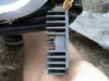
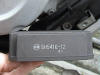
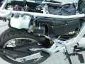
GS VR Installation
Instructions and images by PhilMills, more photos taken from other conversions.
This writeup covers replacing the OEM voltage rectifier on the F650 "Classic" with a voltage rectifier from a 2000-or-later F650GS and relocating the VR outside of the seat pan. The final result will look like this.
Parts Required
- # Voltage Rectifier from 2000 or later F650GS (BWM PN: 61 31 2 346 550)
- Two (2) 12" lengths of red primary wire
- Two (2) 12" lengths of green primary wire
- Two (2) crimp-on ring terminals (6mm inner diameter (or sufficient to fit your battery bolts))
- Four (4) crimp-on wire connectors
- Three (3) .093" molex male pins (crimp-on)
- One (1) 1" Nylon spacer (1/4" inner/ 1/2" outer diameter)
- One (1) M6-1.00 x 75 bolt (10mm head, 75mm shaft, threaded at least last 20mm )
- Four (4) washers that fit the above bolt
Tools/etc.
- Dielectric grease
- Soldering kit
- Electrical tape / Liquid electrical tape
- .093" molex pin tool
- Crimper
- Wire cutters
- Razor knife
- Blue Loctite
NOTE: The molex pins and pin tool can be readily located at Radio Shack (or similar stores). Example: 4 pins, plus a connector to throw away later.
A. Removing the Original VR
- Remove seat and left- and right-side panels from the motorcycle.
- Disconnect the battery - both positive and negative terminals. If your VR has failed, then it's very likely to have damaged/destroyed your battery in the process, so this is a good time to check and possibly replace your battery with a "maintenance free" one (see the BATTERY FAQ).
- Locate the VR under the seat. Remove the two bolts holding it down. Save the washers for use later.
- The VR is connected to the rest of the motorcycle in 3 places - detach them: - Grounding cable to the frame - Connector with 3 yellow wires (goes to generator/alternator) - 2-pin connector that eventually leads to the battery
- Remove the old VR from the bike.
- We will reuse the yellow-wired connector attached to the VR: this is a 4-pin connector with only 3 of the pins in use. Mark the connector to indicate which of the 4 pins is empty. Use the pin tool to pop the pins free from the connector. Retain the connector shell, discard the old VR.
"VR" for the remainder of this writeup will refer to the F650GS voltage rectifier.
B. Prepping the new VR
- Use the razor knife and a lot of care to remove the black wrapping and electrical tape from the wire bundle. The GS rectifier has 3 yellow wires going to one connector, and two each of red and green going to a second connector.
- Cut off the OEM connectors - leave as much wire as possible on the red and green wires, leave 6" of the yellow wires. No source has been found for the mating ends of these connectors, so they aren't useful for this job. Strip 1/2" of insulation off of the ends of the bare wires.

- With the 3 yellow wires:
- Crimp on the molex pins. Use some solder to keep them in place and ensure a good connection.
- Insert the pins into the connector from the old VR making sure to leave the originally-empty pin empty.
- Tape these wires together for neatness.
- With the 2 red wires from the VR:
- Use the crimp connectors to attach a length of red ignition coil wire to each of these wires (we need to extend them to reach the battery from the VR's new location).
- Take one of the ring terminals and connect it to both of these extended wires (both red wires into the same ring terminal).
- Tape these wires together for neatness.
- With the 2 green wires from the VR - repeat the procedure for the red wires, but use the green ignition coil wire lengths.
- Coat the wire connections and entry into the ring terminals with liquid electrical tape to waterproof them.
By this point, the new VR should have:
- 3 yellow wires going into molex connector
- 2 extended red wires going to one ring terminal
- 2 extended green wires going to a second ring terminal.
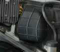
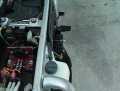
Now we will prepare the motorcycle for relocating the VR - the new location will be outside of the seat pan, adjacent to the coolant overflow tank for the radiator.
C. Removing the snorkel
- Loosen all visible/reachable bolts that hold the airbox top and bottom halves together.
- You should be able to seperate the airbox halves enough to easily remove the snorkel from the airbox.
At this point you must decide whether you'd like to modify or completely eliminate the snorkel from the airbox. If you eliminate the snorkel, you will need to drop the needles in the carberator by one notch. Modifying it will not require any carb modification that I am aware of.
D. Modifying/replacing the snorkel
- Take the razor knife and cut away the outer two "ribs" from the snorkel - this will reduce its overall length by roughly 2".
- Replace the snorkel in the airbox, but don't tighten the airbox back up yet. A flat-head screwdriver may be useful for getting the snorkel back into position.
E. Mounting the new VR
- Locate the bolt that holds on the helmet holder cable - remove that bolt, discard the cable. There is a washer on this bolt - leave it in place against the overflow tank (my bike was dirty enough that it just kind of stuck there). Discard the original bolt as well.
- Take the new bolt, thread it through the VR (fins on the VR go OUT from the motorcycle), add three washers, add the spacer, add the remaining washer (the one that remained from the helmet cable).
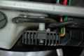
- Feed the wires from the VR through the frame of the bike into the seat pan.
- Thread the bolt into the hole with some blue Loc-Tite (you might consider replacing the threaded clip here with a real nut - while I haven't had any issues after 3 months of street riding, rough roads or off-road use may require more tightening than the original clip can handle).
- Adjust the VR to ensure clearance between the VR and the overflow tank and between the VR and the snorkel (if you're not eliminating the snorkel) before you tighten down the bolt.
- Tighten the airbox bolts back up.
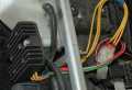
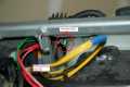
F. Connecting the wires
- The yellow wires from the VR (with connector from the old one) connects back where the old VR's yellow wires came from. Before making the connection, put a blob of dielectric grease in each of the female connectors to prevent corrosion.
- The red wires connect to the positive battery terminal (apply dielectric grease to the ring terminal from the VR, any other wires going to the positive terminal, the terminal itself and the terminal bolt).
- The green/brown wires connect to the negative battery terminal (same procedure with the dielectric grease).
Start the bike up - hopefully everything works. Put the plastic and seat back on.
Alternative Relocation

Misc Questions
How can I prevent it failing (for as long as possible)?
- Get a sealed Battery (See the Flaying the VR FAQ for WHY)
- ALWAYS make sure your battery level does not drop too far.
- Move the VR to a Cooler Place.
- Consider adding in a Relay and a Diode as per the Flaying the VR FAQ.
- Make sure the Ground Wire is Properly Connected
- Don't Wash it with Cold Water when it's HOT.
- Keep it clean and uncovered. i.e. Don't put any cloths
or anything over it or close to it that will prevent airflow (in the Stock
Location).
Surely if it's Overcharging the Battery, this can't be good for the
Battery in the Long-term?
- No, it's not. There is a possible solution,
involving installation of a Relay and a Diode if you're electronically inclined.
See the Flaying the VR FAQ.
- Alternatively you could try FIRST (as it is easier, but not cheaper)
Does Submerging it unduly affect it?
- I've submerged mine on at least two, and maybe as many as
four occasions (not sure how deep the water was in all my crossings). No
problems, with 23k miles on the bike. Robin #790 Chicago '01 GSD
If it fails, can I completely disconnect it so I can get home?
- I've been riding around with the VR completely
disconnected, both plugs, just on battery power on my slightly injured battery.
After charging it fully, and making a start (bike always starts as fast as I can
remove my finger from the button), the voltage is remarkably steady. The CDI
must use considerably less than 1 amp. Running the bike for 1.5 hours my load
voltage with ignition running (with bike running) only dropped from 12.5 to 12.3
volts. (No headlight and only a few minutes with running lights (I have the Euro
switch), modest brake light use, and a couple of minutes of radiator fan use.)
After stopping the bike and restarting it 4 times, the battery was recovering
while running and the voltage was above 12.2 volts and rising. Still get the
same (acceptable) test readings (both BMW and Electrex test specs) off the
stator, even when tested quite hot.
The voltage was quite steady as long as the radiator fan (or headlight, running
lights) wasn't on. The fan is a serious drain. Not sure what voltage the CDI
quits at, maybe 11.2-11.5 volts?, but if you were running on the open highway,
you could run a long time, maybe all day and charge at night. Obviously this
experiment does not apply to the FI or ABS models.
What else could it be if it is NOT the Voltage Rectifier?
What's the Chances of it happening to me?
- Note as always, these are just the ones that
DID happen (and were reported). Lots of Bikes out there are still O.K.
- 1997
78,000 miles, more or less-Odometer died just a week before the VR $150 sounds
like what they charged me. Charlie #070
- '99,
replaced under warranty by a generous dealer at 11k miles due to overheating the
alternator wiring harness and high voltage output. Overcharged OEM battery
60-70% dry ONCE, battery still good. No electrical accessories on bike. New VR
still runs a bit high, close to 15 volts, despite new battery, improved
connectors and new wiring. More than 5k miles since replacement. Dealer said he
services 50-60 F650's regularly each year, has sold many more, says that is only
second F650 VR he has replaced. Todd #389
-
After failure of my Voltage Regulator/Rectifier, I'm wondering if this is a part
that fails often or not. My dealer (CalBMW) had one in stock, but claims to only
have replaced one. My '99 failed just shy of 3 yrs old, 23K miles. Price for the
part is $150. What happened to mine was similar to what happened to Flash. start
the bike and get 14.5V. as the thing warms up, it starts to drop. will stay
around 13V while riding. but drops to below 12 when idling. When I replaced my
battery two weeks ago, the cells on the positive side were quite full, declining
toward the negative side, where the two left-most cells were almost empty. the
battery still worked OK, but I figured it was due... I've always checked my
battery at the called-for intervals, and again when it was convenient. It's been
a few thousand miles since I checked it last. I'm thinking it may have been the
battery, not the PIAAs, that fried the rectifier since I rarely use the lights,
and then only for short periods. if I'm following BMW's service plan, is the
battery my fault or theirs? although the bike is fixed now, I'm not sure yet
whether it'll be a warranty job or not. we'll know within a few days. I replaced
my battery with an AGM maint.-free battery from batteryweb.com for $50. They now
list the battery for the F650, but you still need to lose the little rubber tray
to make it fit.
Mark #403
- As I
have mentioned before, my daughter goes through a battery and VR every 2 years
on her Honda VFR. However, her 1981 BMW R65LS uses a mechanical breaker point VR
that has never been replaced and her batteries last for years. The battery and
VR in my F650 continues to give good service, even after 5 years. I have a
theory. I believe that the latest VRs are set to function at too high a voltage.
The VR in my airhead would cut off the juice at around 13.5 volts, but you had
to ride it a long time to fully charge the battery. I believe that the current
motorcycle electrical engineer thinking is that motorcycles do not get ridden
much and therefore a fast charge is needed to recharge the battery for these
short rides. I'll bet the charging system is putting a lot more current than the
recommended 1.4 amps into the F650 battery. Also, lead-acid batteries can only
handle a limited number of charge/discharge cycles. This, combined with fast
recharges, makes the battery fail relatively quickly and when they fail (usually
by shorting out a cell), they place a heavy load on the charging system, which
then cooks the VR, resulting in the transfer of great wealth from the owner to
BMW. Richard #230.
-
1997F at 6 years and 19,000 miles. Build date, 10/96, the thing is fried, acts
as a 2900 RPM rev limiter and throws 16.9 volts to the battery. Ordering one
tomorrow from the local dealer. Who is Dennis Kirk? Oh and if you're doing the
wiring modification I suggest soldering the diode to the spade connecters and
using heat shrink tubing to cover it. I would also try and attach the relay to
one of the existing ones to utilize the rubber isolation mount. I am still
pondering whether to do it with the new VR. Chris in Santa Cruz, CA #782
- I
have a '99 Classic with 25K miles. Hmmmmm, Dennis Kirk sells a replacement for
about $125 or so. Maybe I should buy one as preventative maintenance. I finally
did find a Radio Slack that had the diode in stock (shock, horror, surprise!!)
so I'm hoping that I can do the VR flay this weekend. I think Richard's
summation of the true cause of the problem is quite correct. Shank NYC USA
- '96F, 47 000k's. VR is still O.K. Bike is on it's second battery. Pete
- My
'96 in France had a truly odd VR failure at about 15,000 miles (I seem to
recall). It would work fine up until the battery was charged and then cut off.
It would not come back on unless you power-cycled the ignition. Worked fine for
the commute. But on the weekend... the bike ran right up until the battery was
flat. Flash #412 (CO)
- Mine
failed at 22,000 miles. '97 ST. Failure was almost certainly due to running the
bike with a dry battery. All BMW dealers I contacted (at least 5 or 6) claimed
to have never heard of the problem. The VR was a special order for around $145
US (Cascade BMW Seattle). Windhunter.
- Mine
failed at about 2.5 years and 25,000 miles. 1999 F650. Part was replaced under
warranty. Craig#325
- '97 F650 at 26,000 on the original VR. Brian 1025
- 97F, 21K miles, still original. Marty #436-Chicago-97 F650F.
- I recently
purchased a second (or maybe fourth) hand F650 Funduro and absolutely love it.
It was originally used by a riding school in the UK for the last 7 years and has
68000 miles on the clock. Originally White but started to look scruffy, then
painted yellow with more runs in it than Ben Johnson and now a professionally
sprayed Dark Pearlescent Purple (looks like black on a dull day but a real eye
catcher when its sunny). Sure it thumps and rattles but it has character. 1000
times better than re-cycled metal and plastic, Characterless "Jap Crap". Had
problems with the regulator. Got second hand one from Motorworks. (UK spares
dealer excellent for new or used parts on Beemers) Wouldn't have even known this
was the fault unless I looked at your site. Saved mega bucks. Steve (UK).
- Can't figure out
why my VR failed again, after barely a year. For some reason, I'm convinced that
a VR shouldn't be an annual expense. For $150 I can't see just installing
another OEM VR. Can't find any specific problem. I suspect a minor intermittent
failure of the stator, as described in the Electrex stuff. Can't duplicate the
problem hot or cold, but I've been thru this before with larger motor windings
and it's not likely to improve with age. Can't find a (working) Megger to borrow
to test the stator under load. Probably wouldn't be conclusive anyway. Decided
to be done with it, going to replace both the VR and the stator with Electrex
stuff in the hope that it will be better quality than replacing it with the same
BMW/Rotax stuff and I can finally be DONE with the problem. So maybe I can
eventually report back if the Electrex system is a decent alternative to OEM.
The fact that Electrex even sells an F650 stator should say something in itself.
I checked my battery yesterday morning and it was HALF EMPTY. YIKES! I was doing
mine every thousand miles at ~500 miles a month (every other month), and that's
fine for the first year when the VR works right. 1000 miles ago I only added
1/4-3/8" of water to my battery. 400 miles ago I only added 1/4-3/8" of water.
Yesterday I added exactly 15cc (close to 2") of water to each cell. I filled it
back up with distilled water and it seems to be fine. That works for me, but for
you that could easily be every week when you are traveling. Might consider
putting a rubber inspection plug in the side cover to make it easy to look at
1-2 of the cells. (I find the cells on the positive side of batteries usually
boil first. I'm QUITE sure I can lower output by disconnecting one of the phases
(one of the three yellow alternator wires). I'm quite sure I can yank the entire
VR and do my regular ride on the battery charge, sans head and tail light. So
what do I do? Take a razor blade and cut the piece of loom from the battery to
the alternator, Replace the wires, Tape it back up? Nah, did that long ago -
those wires are fine. I want to rewire from the VR to the ignition switch, and
back to all the accessories, like the fuses, fan, headlight. Considered putting
in a MOSFET instead of a relay? Yeah, but...unless I can find one that's super
duper bionic mil-spec, I'm not sure I trust that solid state shit from crapping
out just like the VR. There's still a lot of merit in a non-electronic bike. By
"sensing 0 V" do you mean floating open (per below) or hard grounded (as in ZERO
Volts)? Floating open, as in the possibility of a relay failure to actuate.
Grounded is a less likely failure mode, and hell, if any of the red wires
ground, that's almost always a fatal failure mode, with smoke escaping the
wires! ANYTHING has to be at least as good as what we have. Tested things in
detail today, and the VR is crap. Even doing a manual "Flay" (jumper) doesn't
control the voltage down. Despite varying loads and rpm, hard to get it below
14.5 volts. Connections and wiring are fine, and cool, but the VR sure gets very
hot very quick. So my VR failure comes down to a choice. Installing another of
the same crap $150 VR is NOT gonna happen. I guess it's between an Electrex, or
substitute a (hopefully heavier duty, but probably same NipponDenso crap)
400watt VR from the GS, which has an additional ground and output lead. I can
use the extra leads to do a different and improved Flay. Modification is OK -
I'm well out of warranty and I'd have to upgrade the connectors on either unit
to match my harness. Hopefully the GS unit is heavier duty. Todd #389.
- It is very probable
that your problem is due to a defective regulator/rectifier. For a positive
diagnosis do as Todd proposed and check the voltage in your system (with engine
running of course) for a value significantly above 15V. Another symptom would be
a low level of fluids in your battery, due to overheating. I had this damage
occur to my bike 1.5 months ago. Shortly before the problem showed up in full,
and while I was routinely checking my battery, I noticed a very low level of
fluids, but thought it was caused by drainage due to a (mild, Thank God) lowside
I had had a few days before. A couple of weeks later, out of the blue, the bike
would start up promptly and would maintain a healthy idle, but would misfire
EXCESSIVELY (sounding like old, two stroke MZ and Jawa bikes) and would exhibit
almost complete loss of power off idle. These symptoms would be maintained for
more than ten minutes after start-up, then being reduced to a minimum. I took
the bike to my mechanic where he diagnosed the regulator's defect. The unit had
degraded to the point that the base-side of the cover was cracked (due to
excessive heat?). I speculate that, due to the cracked cover (a consequence of
the original malfunction, not the origin of it) moisture was penetrating into
the unit, augmenting the problem; after warm-up (the 10min period mentioned),
the moisture would go away, reducing the severity of the symptoms. The dealer
mentioned that turning the lights on is a known "temporary fix" for a bad
regulator, because it helps with reducing the symptom of overcharging. Of
course, sooner or later the defective unit must be replaced. Replacement of mine
had to be done right away, because of the crack. Note that the
regulator/rectifier isn't cheap. I (located in Athens, Greece) had to pay the
equivalent of about $100. (Labor cost is negligible; given the part, you can do
the replacement yourself, as it involves only tightening two screws and plugging
a socket.). The dealer said that a bad regulator is a "moderately frequent"
problem occurring on F650 units. Perhaps the unit builds up too much heat, given
the fact that it is confined in a closed space under the seat. Maybe that's the
reason why the regulator/rectifier on the new GS650 is placed in the open air,
on the back of the "belly pan". Unknown.
VR Autopsy
An Autopsy of a Classic (Funduro) F650 Voltage Rectifier / Regulator - Failed Classic VR
Yesterday I took
Chris from Santa Cruz' dead VR to the Failure Analysis lab and we x-rayed it. I
have some pictures that I will include in the final report. The cause of failure
was a lead that came loose from what was either a capacitor or diode. It looks
like the component spilled its guts, too. We couldn't see much more, shooting
through the aluminum heat sink.
Chris in Santa Cruz sent me his
dead VR for an autopsy / reverse engineering. This is a composite of two x-ray
pictures of the unit, as received, shot through the heat sink. The three
vertical bars are connected to the phases (yellow wires) of the alternator.
These have diodes stamped into them that engage the two horizontal buss bars in
the middle. One bar is ground (brown wire) and the other is positive "12V" out
(white/red wire). The green "sense" wire is the small one running up the right
side to the regulator portion.
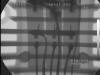
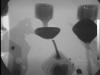 See those blobs near the top of
the picture? We thought those might be capacitors or diodes. Take a CLOSE look
at the one in the middle phase. That doesn't look right. So we zoomed in on it
and saw what is probably the cause of failure for this unit, an open circuit.
See those blobs near the top of
the picture? We thought those might be capacitors or diodes. Take a CLOSE look
at the one in the middle phase. That doesn't look right. So we zoomed in on it
and saw what is probably the cause of failure for this unit, an open circuit.
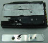 X-rays have to have a lot of
energy to go through metal. The VR is potted in some sort of epoxy. We figured
we'd have a better view if we got rid of the metal and the epoxy. An infrared
spectrograph indicated that this epoxy was a highly cross-linked compound that
probably would not respond to solvents. Sometimes you can heat up an epoxy and
it sort of melts, allowing you to remove the potted components. Not this
epoxy. This would likely heat up until it started to "decompose" which is a
fancy way of saying "catch fire." So I sawed off the heat sink.
X-rays have to have a lot of
energy to go through metal. The VR is potted in some sort of epoxy. We figured
we'd have a better view if we got rid of the metal and the epoxy. An infrared
spectrograph indicated that this epoxy was a highly cross-linked compound that
probably would not respond to solvents. Sometimes you can heat up an epoxy and
it sort of melts, allowing you to remove the potted components. Not this
epoxy. This would likely heat up until it started to "decompose" which is a
fancy way of saying "catch fire." So I sawed off the heat sink.
This allowed us to shoot lower
energy x-rays through the epoxy in the hope of seeing more. We did. If you
look very closely in this picture, you can see evidence of circuit board traces
toward the right end. And there are clearly a few components there.
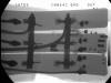
Lowering the beam energy even
more means that you can't see through the buss bars as well. But you CAN see
the traces in the circuit board more clearly.
Since the key to this thing is
that regulator board, we decided to remove it. This was done with a vise and
hammer and screwdriver. The potting epoxy was laid down in two stages and
didn't adhere to itself homogeneously. So we could split it.
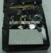
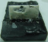
And then out came the
regulator, dipped in white nylon. Here is the regulator. There are two
transistors, three-terminal devices in the lower left quadrant. There are three
resistors, on the left side, probably of two values. In the middle section are
two other components. The one at the top appears to be a diode and the one
below it is probably a resistor. We guess that the diode is a zener diode for a
voltage reference.
We played with the beam energy
a little bit to see if we could get any other clues
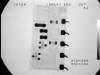
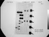
We thought we saw a number and found that we did

These three terminal devices
are either transistors or silicon controlled rectifiers.
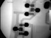
We did mass spectrometry on the
white stuff (in red below) and found it to be a pretty good match to a known
sample of a polydimethysiloxane compound (in blue), commonly called silicone.
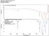
Paul didn't have any of the
hexo-flouro-bad-shit-solvent on hand in the lab that will dissolve most
silicones. So we tried heating it in an oven to 150 degrees C for awhile. Some
of the lighter aromatic stuff left, making it a bit more brittle. But it didn't
melt or liquefy at all. If we heated it up much higher, the solder would start
to re-flow. Silicone is real easy to carve with a sharp knife. So, Exacto-time
it was.
- The IR spectrometer
said the potting material was a multi-strand polymer epoxy. The means it won't
melt, it'll burn. So we didn't heat it up to pull the guts out. Instead, I took
it home and cleanly removed the heat sink off with a hacksaw and hammer.
- In a few minutes, I
am heading back to the FA lab to see if we can read component labels with x-rays
that no longer have to have enough energy to pierce aluminum. More as it
develops. My one comment so far is that this thing appears to be as crude as all
get-out.
- Two things. First,
what looked like a diode or cap, viewed from above through the aluminum, was
actually a solder joint. Next, NFW was Interesting. I know how hard it can be to
identify such things thru an x-ray profile. Paul thought they were caps or
diodes, too. And he's the one with the keys to the x-ray machine.
- Anyway, we surmise
that it might have been a cold solder joint perhaps with bad-ass electro
migration that caused the circuit to open. Interesting. With the potting, likely
it was overheating, and not using higher temperature/stronger solder, which
saved them 3 yen per unit. Just curious - were there any air voids/bubbles in
the potting material, or was it rather solid?
- I'll make the
photos available in the report. Paul is gonna be around next week. I'll be at
work Mon and Tues, but my boss won't. So likely Paul and I will finish poking
around and I will do the write-up and post it where you can see it. Do you want
me to post it "privately" for you and K. for pre-release discussion?
- We also have a 10m
anechoic EMI chamber and complete environmental lab (altitude as well as temp
and humidity).
- I wonder if the
cause was overheating, or vibration? I'm curious because some such (heavy diode)
connections are "stamp welded" for assembly, and sometimes bad ones vibrate
loose when subjected to heating and cooling cycles.
- Two things. First,
what looked like a diode or cap, viewed from above through the aluminum, was
actually a solder joint. Next, NFW was vibration an issue in this epoxy potting.
The diode connections were "stamp welded" I guess, because as near as I can
tell, when you pull the buss strips off, all you are pulling them off of is
silicon.
- Anyway, we surmise
that it might have been a cold solder joint perhaps with bad-ass electro
migration that caused the circuit to open.
- Q. So which
portion was the failed connection in? The rectifier, or the V control hybrid
part? A. BETWEEN them. The regulator has six terminals. One was upgefuhkt.
- Not surprising that
it's a hybrid chip (but it's a PITA!) Nippon-Denso is certainly big enough to go
that route (designing their own) for manufacturing. If you guys are looking at
the chip, you must have an x-ray electron microscope - those suckers are cool! -
I used to repair a couple in a previous job.
Failed Electrex VR
Finally talked to Ritzo at Electrex.
- Turns out that he
sent my exploded VR to England for testing. (Maybe dissection or x-ray?) He
tested it before forwarding it, and said it was still functioning, in spite of
the obvious rupture. (I have to admit that I didn't test it after the failure.)
He's expecting some response from England, hopefully this week.
- He says he is
interested in sharing whatever he finds, so we'll see what they find out.... I
did previously mention that I received the replacement VR from them last week,
but am in no hurry to install it?
- In analyzing your
VR dissection, you might want to take a look at this:
http://www.tympanium.com/design.html especially in terms of comparing your
circuit to his comments on "shunt" vs. "series" SCR's in VR's. It's a good
summary of some of the VR operating characteristics we have been looking for.
Don't gloss over it - while it still leaves me with a couple questions, a couple
points make me rethink what I thought I thought about controlling VR's.
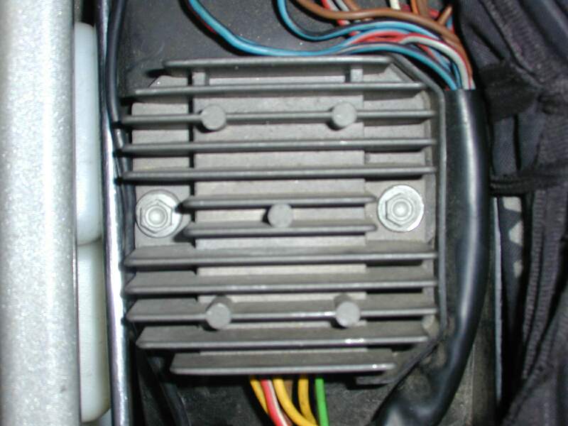
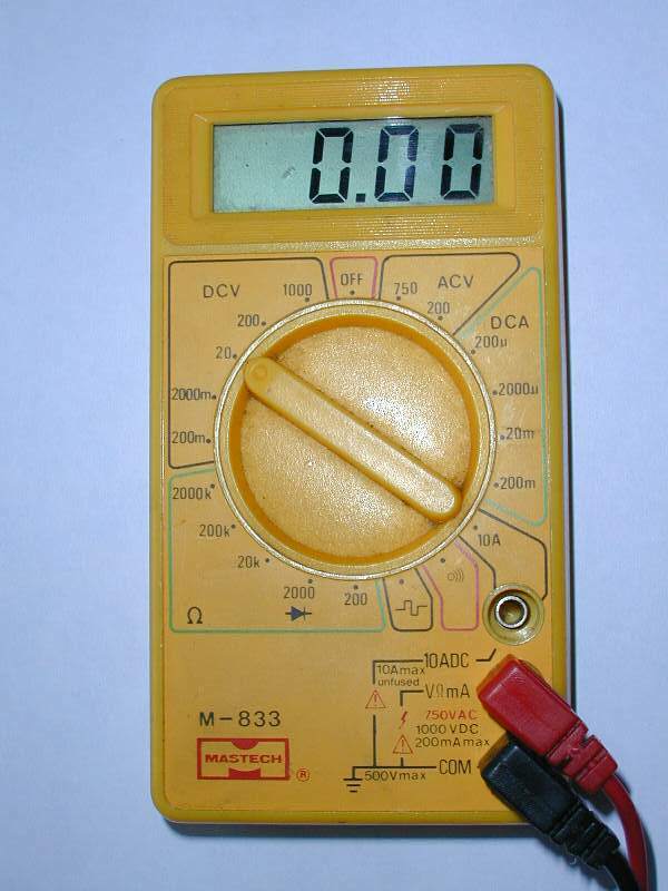
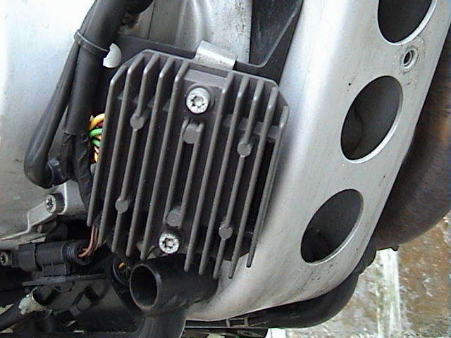
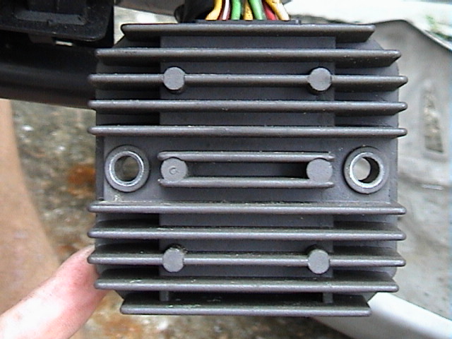
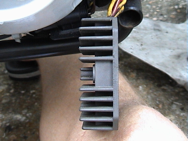
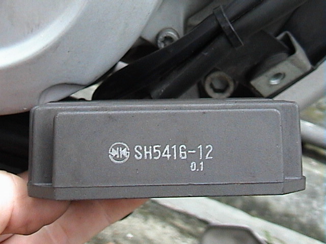

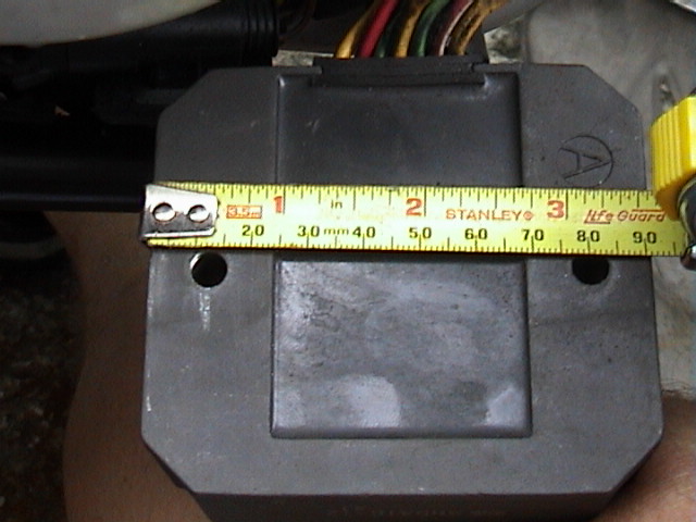
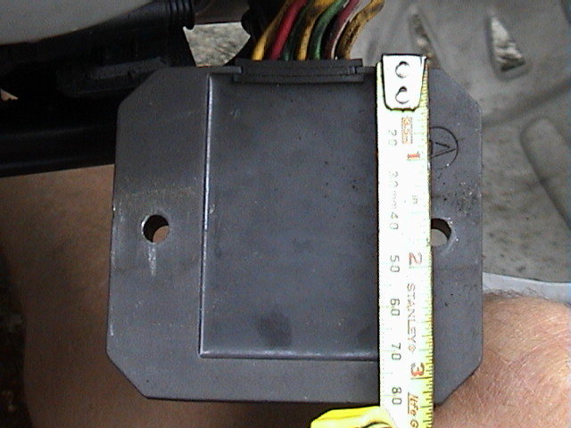


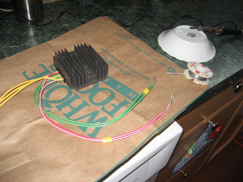

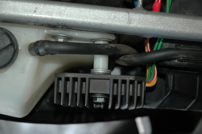
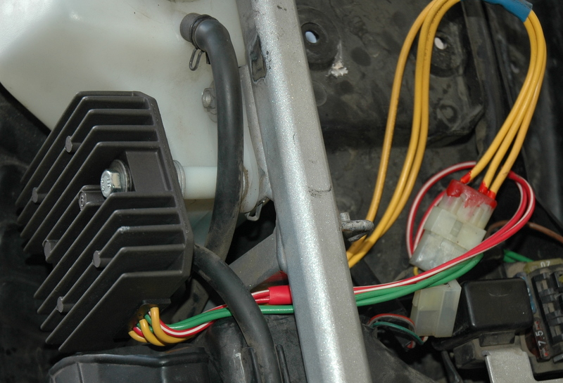
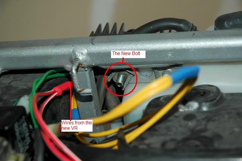
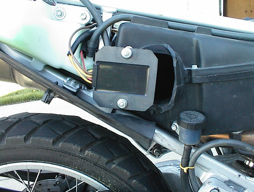
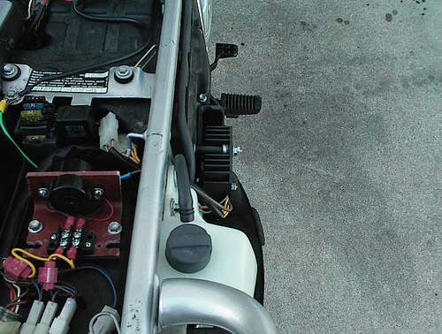
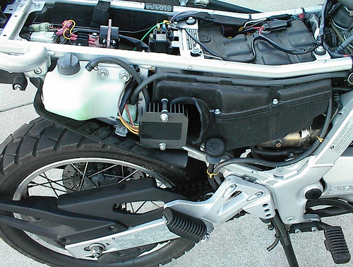
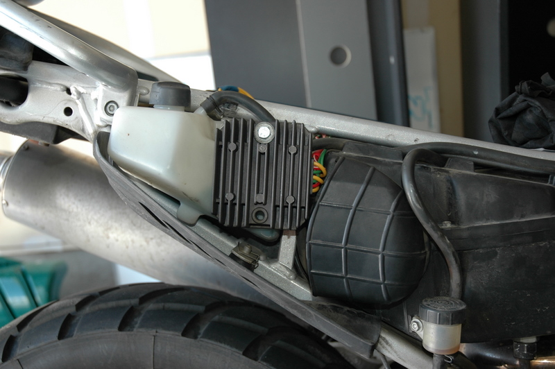