FRONT BRAKE SWITCH FAQ
Please read the Disclaimer before attempting any work in this FAQ.
by Marty #436 & Jim Powell. edited by Kristian #562
For Details on making the BRAKE LIGHT work, see the Brake Light FAQ
F650 Classic Front Brake Switch
Replacement FAQ
by Marty Graves #436
Symptoms:
A typical failure of the front brake switch is indicated by the rear brake light not actuating when the front lever is squeezed, but actuating when the rear brake lever is pressed. Be aware that the same symptoms can be caused by a fault in the wiring harness or a switch out of adjustment (see troubleshooting section).
Method of Activation:
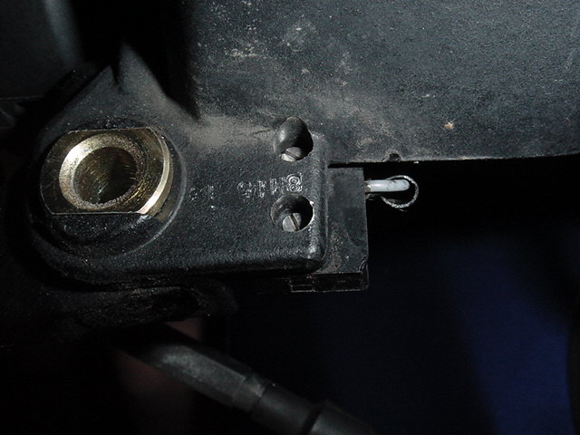
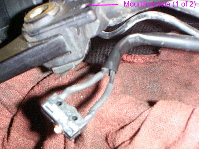
The switch is secured to the underside of the brake lever perch, using two TINY screws and nuts through slightly larger holes in the switch (to give limited adjustability). The tiny "tit" on the micro-switch that activates the electrical contact is not actuated directly from the brake lever, but by a sliding plastic "actuator" (a.k.a. druckstuck) that slides in a bore in the lever perch between the brake lever and the switch.
As the brake lever is squeezed, it compresses the fluid in the master cylinder, which provides the braking. The part of the brake lever that controls the brake light switch is on the opposite side of the lever's pivot, so it releases pressure on the sliding plastic actuator. This allows the spring action in the micro-switch to work, sliding the actuator toward the lever and allowing the switch to go to its relaxed state, which is "normally closed." This turns on the brake light. Releasing the brake lever reverses the sequence, actuating the switch, which breaks the contact and turns the brake light off.
Troubleshooting:
Please read the WHOLE procedure before starting work!!!!
This assumes that you have the symptoms above. The first step is to listen carefully as the front brake lever is slowly depressed and released. You should hear a tiny click if the switch is adjusted properly (the switch can still click but be broken). No click would indicate a possible mis-adjustment of the switch (handguards can interfere and cause this problem). Slightly loosen the nuts securing the switch to the lever perch (do NOT remove them yet, they are EASILY lost). Slide the switch as far from the lever as the limited adjustment allows. If the brake light STILL doesn't go on, carefully remove the switch nuts and screws (don't lose them), and allow the switch to come out. Be careful that the switch actuator does NOT fall out of the lever perch and get lost. Try the brake light again. If it doesn't go on with the switch out, it is likely bad. The quickest way to be sure is to short the two brake switch terminals together to see if the brake light goes on. This is hard to do, as the terminals are heat-shrink wrapped. If this makes the brake light come on, you can be sure the switch is broken (and you still have the option to reassemble the bike at this point, while waiting for parts). You can order the $TOCK BMW part (which comes complete with the wiring harness), or go the cheaper route that follows.
DISCLAIMER: this is what worked for me. I have experience in doing electrical-type work, and assume that you do as well, or you wouldn't be considering doing this repair. I will not take responsibility if you succeed in breaking your bike. Allowing the switch leads to come in contact with any ground may cause the fuse to blow, or worse. Also, operating a hot soldering gun near a fuel tank involves a certain amount of risk (you be the judge); sufficient ventilation and a fire extinguisher are suggested. Other suggested safety items are heat resistant gloves and safety glasses.
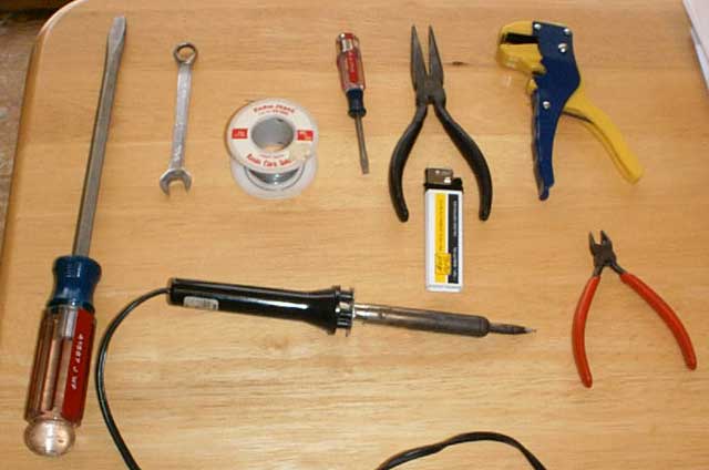
Tools:
Refer to the picture (clockwise, sort of). You will need these tools (or similar) to do this repair:
BF Screwdriver (to remove handguard)
10 mm wrench (nut on handguard)
Rosin core solder
LF Screwdriver (for tiny switch bolts)
Needle nose pliers (or equivalent, for tiny switch nuts)
Wire Strippers
Small sidecutters
Soldering iron
Lighter (for shrinking heat-shrink tubing "in place")
Parts:
1 small black tie-wrap (to replace the one you will have to cut)
2 small pieces of heat shrink tubing (each approx. 1" long by 3/16" OD)
Dab of black silicone RTV
2 dabs of weak LocTite (optional, see text)
1 replacement switch (see below)
The BMW OEM switch is a Cherry DC1 water and dust-proof microswitch, rated 5 amps at 110 volts. The OEM switch is configured as "normally closed" only, I have found a source for a "generic" Cherry DC1 switch that can be configured as normally closed or normally open. These are three terminal (generic, for both N.O. or N.C.) micro switches with solder tabs. This assumes the skill to solder & re-heat shrink the switch onto the wiring harness, and which terminals to use (ignore the center one).
This replacement switch can be purchased on-line from happcontrols.com, Part # 95-0863-00, for approximately US $2.50 ea + shipping ($4.50 for shipping a pair, in my case). More technical information on these switches can be found at Cherrycorp.com.
Preparation:
A day (or more) ahead of time, take the side-cutters and clip off the center tab of the "generic" switch, as close to the switch body as possible. Then put a small dab of black RTV over the remnant to keep water from infiltrating down the tab to the inside of the switch, and to electrically insulate that terminal "just in case." Be neat here (use a toothpick or similar), as too much RTV will make it more difficult to solder later, or will keep the flat side of the switch from lying flat against the lever perch. Allow the RTV to cure.
Below (L to R) is the original switch (with terminals cut to remove it from the bike), the unmodified generic switch, and the finished, modified switch.
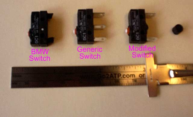
The round, black blob in the upper right hand corner of the picture is the actuator (a.k.a. druckstuck), which should be removed for cleaning. The recess that it fits into can also be cleaned (Q-tip). I would suggest either NO lubricant or a "dry" lubricant (I used a graphite based lock lubricant on a Q-tip).
If you should manage to lose the actuator and wish to fabricate a new one (rumor is that you can't buy this part) it is a cylinder 0.201" tall, and 0.209" in diameter. It has a slight flat spot (see about 8 o'clock in above picture) along the length of the rounded side, the diameter (flatted side to rounded side) is 0.201".
Procedure:
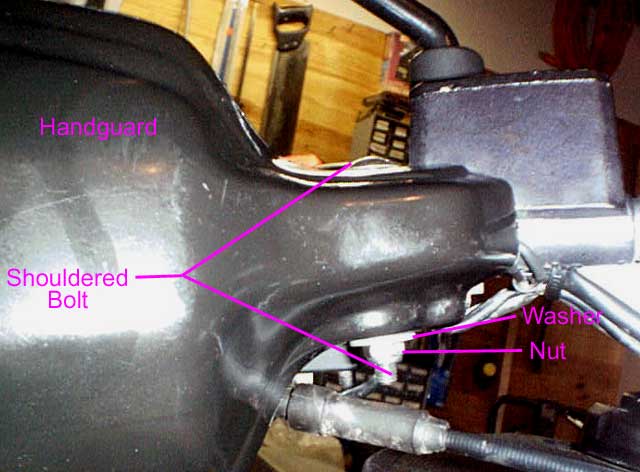
Remove the handguard, if present. On the BMW OEM guard, hold the bottom nut and washer while unscrewing the bolt from the top. If the bolt does not come out after the nut and washer are removed, tap it upward with a drift and hammer. You're on your own if you have aftermarket guards. I suggest putting the handguard, nut, bolt, and washer back together as they came apart (but off the bike), to serve as a reminder (for later) on how they came apart.
Remove the tiny nuts from the switch (don't lose them!), by holding them from underneath while unscrewing the bolts from above (I used my index finger to hold the nut tight against the switch while unscrewing the bolt, then gently removed my index finger with the nut laying on it). Remove both of the nuts/bolts I suggest screwing the nuts back onto the bolts (off the bike) to make it harder to lose the nuts.
At this point, the switch is free to fall out of the perch (so is the actuator, so catch it and/or remove it for cleaning and safekeeping). Cut the tie-wrap that holds the switch leads to the handlebars (the one closest to the grip). This will give you some working room, as we want to "play it as it lies" to minimize the amount of work.
Complete your troubleshooting work as above (as a reminder, be sure that the ignition switch is ON during the testing, or the brake light is guaranteed not to light---a good double-check is to press the rear brake lever to make sure IT activates the light). Assuming that you have officially condemned the old switch, take the sidecutters and cut both leads approximately 3/8" away from the switch, leaving as much wire as possible on the stock wiring harness. Be aware that touching either of these cut leads to a ground on the bike MAY result in a blown fuse (or worse on a fuel-injected bike, but that's a different FAQ). Touching the two cut leads together MUST light the rear brake light, or the switch was not the only fault (this is why it is better to jumper the switch to check BEFORE cutting).
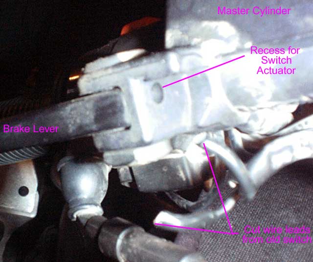
The picture above indicates what it should look like at this point. You probably want to stop to put some type of protection over the bits of bike in the general working area to protect from scratches and hot solder. Using the sidecutters (or other appropriate tool), remove the heat shrink tubing from the ends of the wires, without damaging the insulation. Cut the soldered bits off the end of the wires until you get to fresh unsoldered wire, leaving the existing wires as long as possible. Using the wire strippers, strip off about 3/8" of insulation from each wire, and give the strands from each wire a twist to keep them neatly intertwined.
Slide the heat-shrink tubing over each wire, sliding it as far as possible away from the switch (into the tube covering the wires) as possible. You don't want the heat-shrink tubing close enough to the soldering area to prematurely shrink.
Re-install the actuator into the lever perch, paying attention to which way the flat side is keyed into the perch (flat facing down on my bike, and it should slide in easily).
Orient the switch. Notice how the "tit" needs to be closest to the front of the bike, so it is on the actuator when the bolt holes are aligned. Decide which wire needs to go on which switch terminal, and which direction will work easiest for cable routing. Insert the wires through the holes in the switch terminals, leaving minimal bare wire above the terminal. (Proper form would be to "pre-tin" the wires with solder first, but it would be nearly impossible to get them through the holes in the contact afterward).
Solder the wires to the selected terminals, using the soldering iron and rosin-core solder (never use acid core solder for electrical work!!). Be aware that the bike has a gasoline (petrol) tank on it, and this COULD be a fire hazard if you are not careful. Pay special attention to not use excessive amounts of solder (the heat-shrink has to slide over the work) or have "drips" hanging off the side (where they could possibly make contact with the metal lever perch and possibly ground out when the switch is mounted). Avoid cold solder joints. Use the small sidecutters to remove any excess solder or loose "frizzed" wires that didn't get soldered, and touch up any sharp edges with a small file.
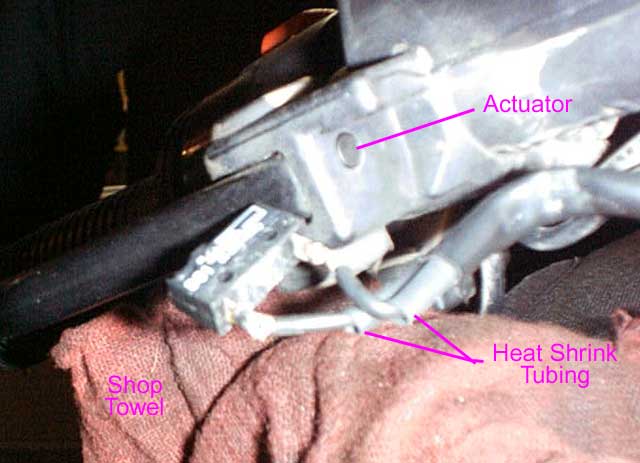
The work should look as the picture above. Slide the heat-shrink tubing back down over the wire/solder/terminals as close to the switch body as possible. Carefully use the lighter flame to "shrink" the tubing in place. Get it to shrink snugly, but be careful not to melt it through or burn it. Again, the open flame near a gasoline tank COULD be hazardous.
The picture above shows the work so far. Position the switch under the lever perch, and drop one bolt through the perch and the matching hole in the switch (I put a dab of LocTite on the end threads of each bolt first but I have been told that LocTite will hurt certain types of plastic (like switch bodies?), so use your own judgement). Carefully, hold the tiny nut up to the bolt sticking through the switch, and tighten the bolt (using the LF screwdriver) until the nut is well engaged on the bolt. Repeat with the other bolt. Position the switch, and tighten the nuts up snug, but not tight (so the switch can still be positioned by hand pressure).
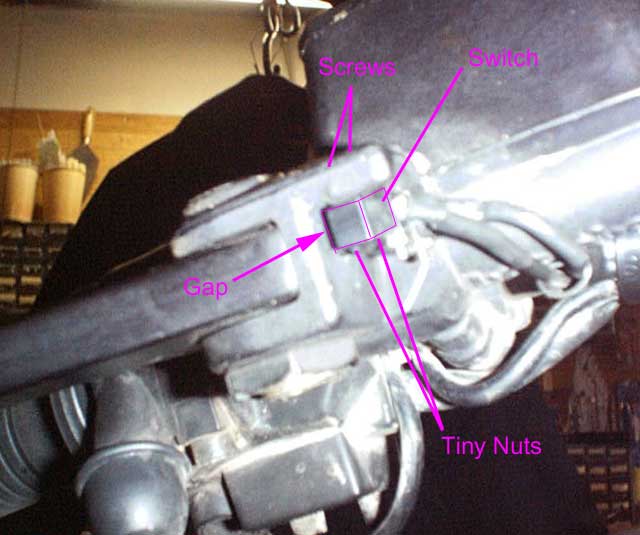
The work should look as above. The switch position now needs to be adjusted by varying the distance and angle between the switch and the actuator (see the "gap" indicated above). This procedure is backwards and very counter-intuitive I kept moving the switch closer (without success), and eventually moved it away (success). Just play with moving the switch around while testing the brake switch actuation by squeezing the lever. Try to get the switch in the middle of the adjustment range, then tighten up the nuts and bolts using the long-nosed pliers (or equivalent) for the nuts (I hate using pliers, but don't have any wrenches THAT small). Re-check the switch actuation. Re-install the tie-wrap that secures the lead wires to the handlebars.
Re-install
the handguard. Recheck the switch operation (sometimes the handguard interferes
with the switch
see a separate FAQ). You should now be good to go until next
time (4 years, in my case). Go for a good long test ride, you earned it.
LMG2 (Feb.7, 03)
Adjusting F650
Front Brake Switch
by Jim Powell
I noticed that after installing the grip guards on my F650, that the front brake no longer activated the brake light. Further investigation showed that the switch would activate but the brake had to be squeezed very, very hard. Much harder than it would even take to lock the front wheel. Not good. I asked for advice on the Chain Gang and they put me on the right track.
Here's what I found. When installing
the grip guards, the stock brake switch cover is removed and the guard is
installed in its position. The guard is poorly designed with no clearance
where the switch is located. This causes the guard to push the switch in
closer to the brake lever so that the brake lever has to be squeezed extremely
hard to allow room for the small switch to push the actuating piston back and
let the light activate. The switch is a normally closed switch. With
the brake lever at rest it pushes a small piston in and activates the switch
contact, breaking the circuit. When you pull the brake lever, the spring
action of the switch contact pushes the piston into the lever assembly and the
switches closes letting the brake light up. See what I mean
below.
|
|
|
|
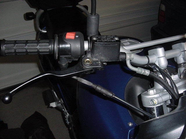
Here's a pic of the brake lever with the grip guard removed. |
The problem is that the switch is pushed in too far toward the lever. |
|
|
|
|
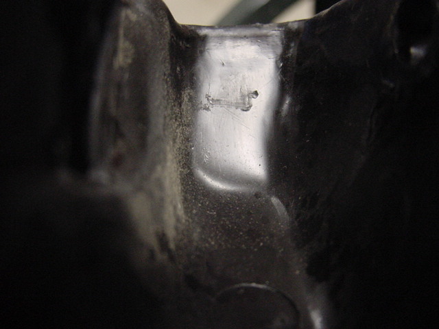
The guard is the problem. There is no clearance. See the scratch marks on the inside of the guard where it has been rubbing against the switch? |
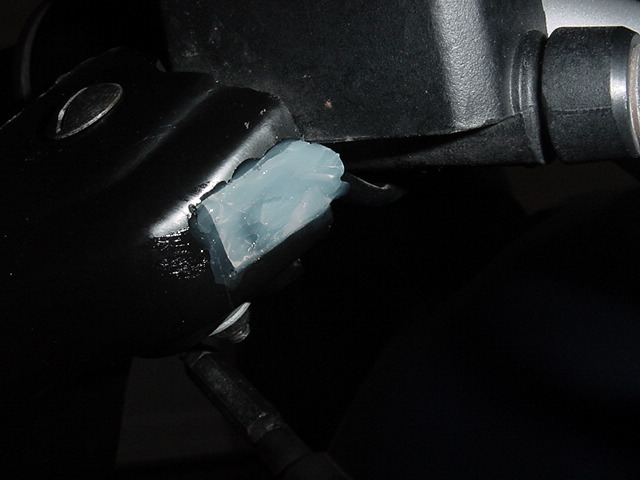
There are probably any number of ways to solve this. I just cut a slot to allow the switch to be further away from the lever. This leaves the switch exposed to the elements. I applied some clear caulk to seal the area. I'll probably reapply it in black one of these days. The caulk above is fresh and will cure clear. Smear to seal properly. A wet finger works as well as anything else. |
NOTE: The switch is held on by two tiny screws and two tiny nuts. There is also a little piston inside the lever frame. All of these parts are tiny. All of them will fly miles away if you drop them. And it will probably be expensive. The good news is that they don't even have to come off. You do need to slightly loosen the two screws so the switch can move about. Let the brake lever sit at rest. Then slide the switch up until it just pushes in and turns the brake light off. You'll see what I mean if you have the ignition key turned on. Do this adjustment with the tail of the bike up near something like a garage door so you can see the brake light going on and off in the reflection. Once the light just goes off, tighten the screws. Nothing removed, nothing to get lost. Now modify the grip guard in any method you choose and reinstall. Test the brake light. Repeat your trimming method as required. Seal to weatherproof if you do what I did. That's it, go ride the bike!
The BMW OEM switch is a Cherry DC1 water and dust-proof microswitch, rated 5 amps at 110 volts. The OEM switch is configured as "normally closed" only, I have found a source for a "generic" Cherry DC1 switch that can be configured as normally closed or normally open. These are three terminal (generic, for both N.O. or N.C.) micro switches with solder tabs. This assumes the skill to solder & re-heat shrink the switch onto the wiring harness, and which terminals to use (ignore the center one). This replacement switch can be purchased on-line from happcontrols.com, Part # 95-0863-00, for approximately US $2.50 ea + shipping ($4.50 for shipping a pair, in my case). More technical information on these switches can be found at Cherrycorp.com. Marty#436.
Radio Shack # 276-1101 50 volt 1 amp silicon diodes 1N4001, 2 for 70 cents in a blister pack, a shelf item carried in any Radio Shack store. Though I was looking at the glass cased 1N914 or 1N4148 ($2/10), smaller and higher temperature, but I'm not sure they are suitable due to much smaller capacity. Any useful comments on the 1N914 or 1N4148 as opposed to the 1N4001, Flash or anybody? Todd #389.
I think
that this might be it. You must break the metal lever off. And one of the
contacts, the normally open one, is not used. So you can break that off, too.
Radio Shack Switch: Flash 412 (CO). If the link no longer works, look for
Cat # 275-017 or CatNo.275-0017.
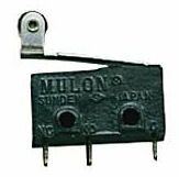
Submini Roller Switch (275-0017) Specifications
Faxback Doc. # 14468
Contacts: ............................................................ SPDT
Power Rating:.................................................. 5A, 250V AC
UL Listed:...........................................................E41364
Operating Force:....................................................5 Grams
Roller Lever Length:...........................................3/4 Inches
Dimensions
Height:.......................................................3/4
Inches
Width:........................................................1/4
Inches
Length:.......................................................3/8
Inches
Specifications are typical; individual units might vary. Specifications
are subject to change and improvement without notice.