GS Valve Shim Check & Change FAQ
compiled and edited by Kristian #562
updated by Brad #1002 and Scott #1244 for ABS equipped bikes
Please read the Disclaimer
before attempting any work in this FAQ.
Last Updated: April 2010, by Scott ID, #1244
For other related FAQs:
Section 1: Introduction
This is a simple job you can do yourself and save some money doing it.
BMW recommend the Valve Clearances are checked every 10,000km or about
6,000 miles. Note that unlike the Classic F, the F650 GS/Dakar
Service Schedule
notes that Valve Check is "No longer included in the 600 mile
inspection as of MY2002".
See the Classic F's
Valve Clearance Check and Shim Change FAQ for details of the
changing of Shims procedure, if you have determined you need to do this.
There are some additional notes on what to watch out for when
changing shims on the GS below, in the FAQ
GS Valve Shim Adjustment.
If you are NEW to this procedure, it is HIGHLY recommended you look at
the Classic Valve Check
FAQ first, as a lot more detail is given in that FAQ. The
Chain Gang Maint DVD (number 1) also shows this proceedure being performed
on a classic.
| ABS Equipped Bikes |
|---|
|
CAUTION: If your bike is equipped with ABS brakes you may
face an additional challenge doing this procedure should you need to
actually ADJUST the valves. Checking them is NOT a problem. If you find
you need to adjust the valves you may have to remove the cam chain
tensioner bolt. The ABS pump location makes removal of this bolt quite
difficult. This is described in more detail later in this FAQ. It is noted
here to allow you to plan accordingly. (See
Alternative Method / ABS Bikes below for
additional information regarding ABS-equipped bikes) Scott, ID, #1244
Ed. Note: Several people have now reported success doing a valve
adjustment using the alternative method. (December 2005)
|
| 2004-2006 Dual Spark GS |
|---|
|
The method for checking the valves on the 2004-2006 Dual Spark
GS is almost exactly the same as below. The only real difference is there
are TWO spark plugs. The valve clearances are the same as for single-spark GS models.
If you are changing the shims on the 2004-2006 Dual Spark, it is
different. The shims on the 2004-2006 GS are UNDER the buckets. It
is noted here to allow you to plan accordingly.
So What? This means that to get the shims out on a dual spark GS
you MUST remove the bucket. This means the cams will need to be far enough
out of the way to get to the buckets.
|
Section 2: GS Valve Shim Check
Original Write-up by by Paul. Updates, Photos & Revisions by Kristian #562
Feb 2002
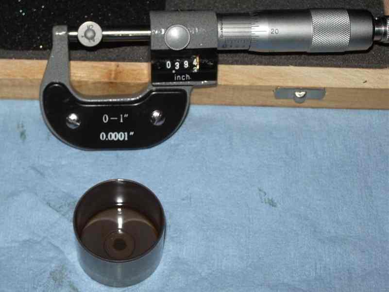
Tools
- Set of Feeler Gauges with gauges
in the approx. range 0.03mm - 0.30mm. Get a set with 0.01 increments between
0.03 and 0.10. What is important are the increments between the numbers,
so you can measure the clearance to an accuracy of 0.01mm. Don't forget you can
double up the gauges, so if you have gauges that go from 0.03 to 0.10 in 0.01
increments, i.e. 0.03, 0.04, 0.05...0.09, 0.10, then it jumps to 0.15,
0.20, don't fret!. Just add 0.05 and 0.06 and you will have 0.11, add 0.05 and
0.07 and you will have 0.12 etc. Don't worry if yours don't have an 0.35mm or
0.45mm, just add 0.20 and 0.15, or 0.15 and 0.30 etc. (Thanks to Aleksander in
Dubai for the Q's :-) ). Hopefully your Classic Valves will not be less than
0.03.
- Torx Keys (In BMW Toolkit) to take "Faux" tank off or use
this Great
Tool. The Screwdriver head is magnetic and the bits stay in. Sizes you
need include T15,T25,T30,T40,T45.
- 3/8" Ratchet with Six Inch extension and 10mm socket
- Needle nose pliers
- Tin can to hold parts (or you can use a sheet of cardboard to
'stick' bolts into, easy to draw a diagram of the part they came out of too)
- Allen Keys (In BMW Toolkit) to take tank off and turn the Crank.
- A Large Screwdriver or Coin to remove Plastic Plug
in RHS Engine Cover. (Not ABSOLUTELY necessary)
- Torque wrench(s) for a 2nm to 40nm range
- Spark Plug Spanner (in the BMW tool kit, 18mm)
- A Top Dead Centre (TDC) Bolt. Here is an
Original
TDC Bolt. This is nice to have, but not ABSOLUTELY necessary for
checking valves, as discussed in the separate TDC Bolt FAQ.
For changing shims, highly recommended.
- The TDC bolt can be made at home. On the GS it is an M 8X1.25 bolt
at least 40mm long. (50mm is better).
- A torch (flashlight) is useful to see the Timing Marks and to put
in the TDC Bolt.
Parts
- Parts you MAY need are some more
Valve Shims if the clearances are actually out
of specification.
See the Misc. Valve Questions FAQ
for more information.
- Crush Washer for the TDC Plug (copper).
- Crush Washer for the Chain Tensioner Bolt (aluminum).
- A few small hose clamps to replace the 'one time use' BMW OEM clamps (optional)
Specifications
NOTE: There are
three different clearances in three different sources of literature (all values are for COLD engine):
From: F650GS
Technical Data Sheet
Intake: 0.10-0.15mm
Exhaust: 0.25-0.30mm. THESE ARE SUPERSEDED.
From: F650GS Service Manual on CD ROM:
BMW Part Number: 01 79 0 009 824 (11/99 Edition)
Intake: 0.05-0.10mm
Exhaust: 0.25-0.30mm. THESE ARE SUPERSEDED.
-
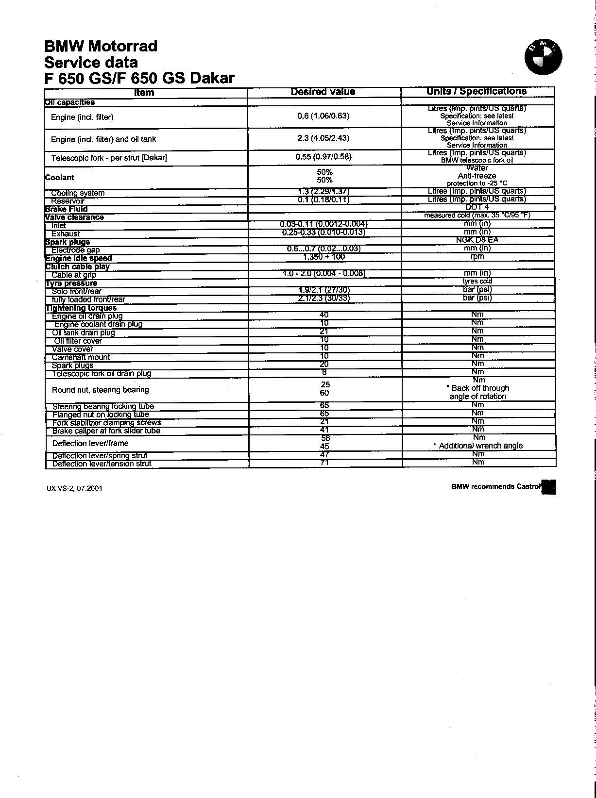
From: F650GS Service Data Sheet (07.2001)
Intake: 0.03-0.11mm
Exhaust: 0.25-0.33mm. THESE ARE CORRECT VALUES FOR BOTH SINGLE SPARK AND DUAL SPARK MODELS.
| Testing The Gap |
|---|
|
The idea is that the gap should be anywhere between or EQUAL to the
specs. The large feeler gauge should NOT fit between the cam and shim.
(OK, a REALLY tight fit is probably acceptable.) The small gauge MUST fit
between the cam and shim. (If it doesn't... you are likely on your way to
a burned valve.) The ACTUAL GAP will be anything in between. Since the
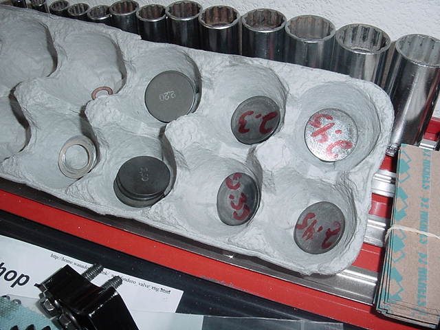
shims only come in 0.05 mm (0.002") increments, there is only ONE
shim that will put you within the proper range of adjustment. I don't
generally do all the math. I just stick the feeler gauges in and the
small better go and the large better not go. If that isn't what I find, I
stick the next gauge in (up or down as required). Normally you don't jump
two shim sizes in 6k miles. So this is just a verification check. Measure
the shim that came out and put the next size, up or down as required in
there when you put it back together. Flash#412
|
Removal Procedure
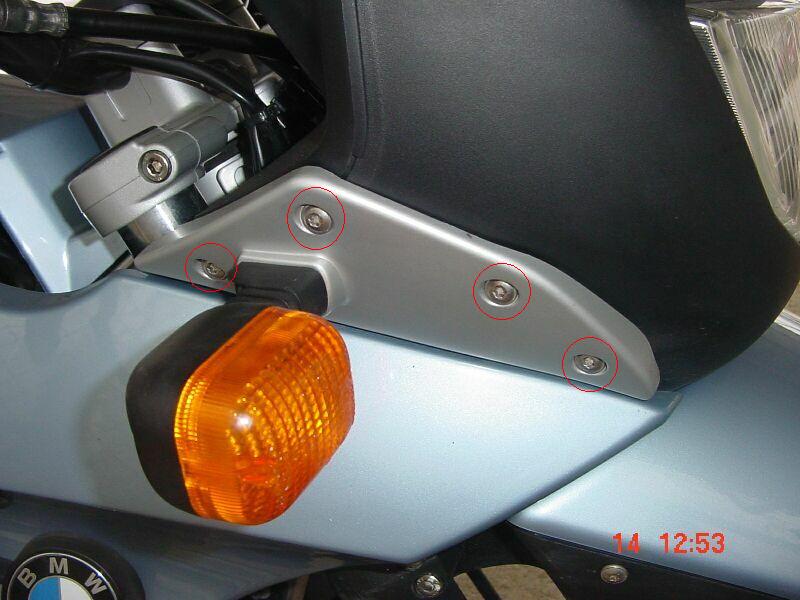
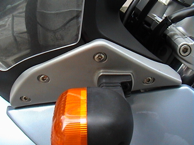
- Before checking the valves, be sure the engine has cooled to room temperaure. (Clearance values are for cold engines). Remove the seat. Undo the four screws that go through
the
silver-colored plates to which the front turn signals are attached. When
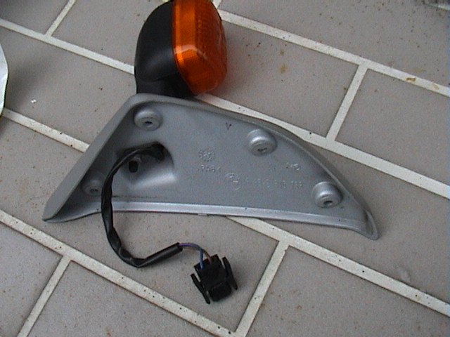
these four are removed, the turn signal will hang. That's OK. Here are the
left and
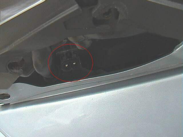
right turn signals (four Torx each). You can
unplug the
turn signal wires (Just squeeze the black tabs at the sides and pull
gently) if you want and
remove them completely from the bike (very good
idea).
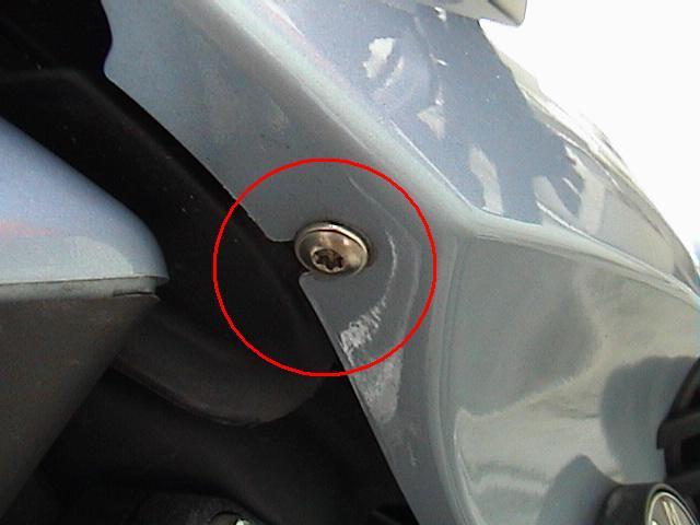
- Remove the left and right fake gas-tank panels. More Torx screws
like the turn signals. Including the Turn Signal Mount screws, there are
Seven Torx Screws for each side Panel. Six of the total seven
Torx screws are removed and
one is loosened.
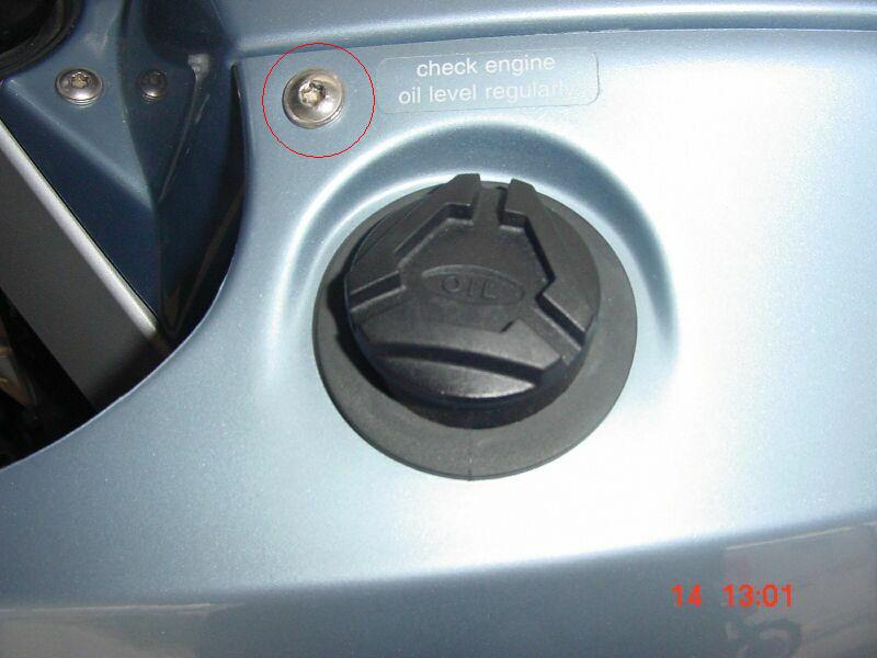
Now remove the following: the
left-most
screw that is exposed when the seat is removed, the
screw at the front
of the "gas tank" slightly forward of the black filler cap.
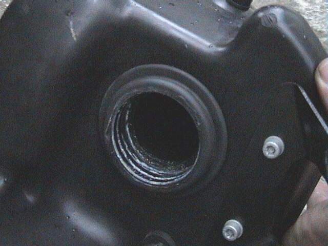
- Remove the black
oil filler cap before
taking the left side off. Then put it back on. The lower part of each
"tank" half fits in a
rubber
grommet. Be gentle or you will break the
male fitting on the panel. Use
Vaseline on the grommet before installing the panels and assembly/disassembly
will be easier next time.
- Now remove the
two screws
that hold the center panel in place and remove the Panel.
- Disconnect the battery, negative terminal first. Remove the
Plastic Overflow
Tube from the RHS of the Battery. Remove the rubber clamp
holding the battery in. Take out the battery. Mine was low on water. In front
of where the battery was (with the red + wire on it) is the
starter relay.
Pull up on it and set it over to one side. No bolts.
- There's a
black plastic cover over the
Electric Equipment Box under where the relay was. Remove
the one bolt with the Torx wrench and remove the cover.
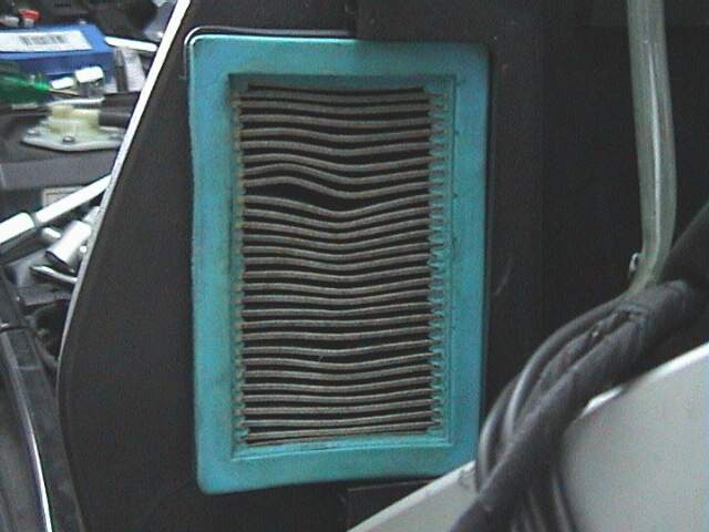
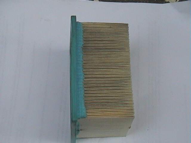
- Now remove the air intake housing. (The big black plastic thing
under the fake Gas tank). You night like to remove it in two bits, the
Snorkel First, to expose the
Airfilter
(and check it) then the remainder of the Airbox. To remove the snorkel first, unscrew the two
Torx Screws, and
on the right side
a Sensor Connection
needs to be removed. Press in on the
metal clip
and pull down. Gently
disengage the Snorkel, taking care not to break the plastic nib at the front of the
Snorkel.
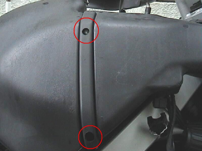
- When removing the air intake housing as one unit (the part that the
air filter fits into), there are two
Torx fasteners at the
rear of the housing which need to come out. (The fasteners for the tank panels
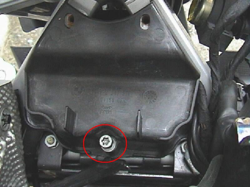
screw into them also). There is also one more fitting that needs to be removed. That's the
one bolt
which attaches the oil tank to the intake housing. If you decided not to
remove the Snorkel separately, on the right side
a wire
needs to be removed. Press in on the
metal clip and pull down. There are
also two 10mm nuts under where the battery was which
should be removed. These can be accessed using a 10mm
socket, six inch extension, and ratchet.
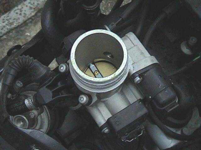
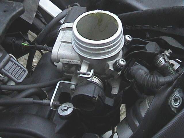
- With all the fasteners removed and the wire disconnected, pop the
housing up off
the throttle body. There's no clamp.
If you didn't remove the Snorkel Part first, note that there's a plastic pin on the nose of the
housing all the way at the front that needs to come out of its
rubber grommet.
Just pull back and lift the housing up and to the right and let it
hang by its
hoses. (Tube2). I put a couple of pieces of duct tape over the opening of the throttle
body. A hose clamp can be used to replace the BMW single use clamp on the one
vent line if you prefer to remove the unit completely. Just cut the clamp off
and pull the hose carefully off the fitting (don't pull the fitting out of the
housing). Use a new multi-use hose clamp during assembly.
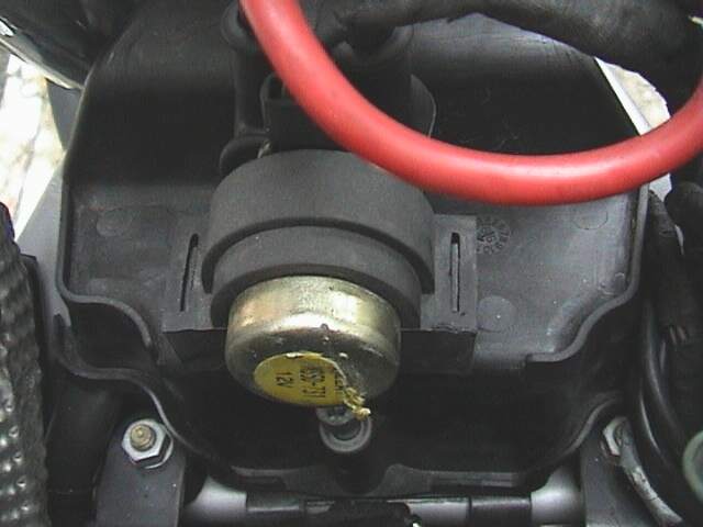
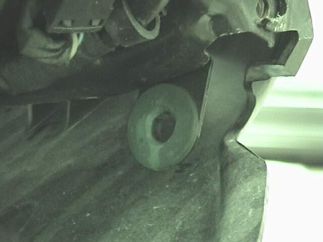
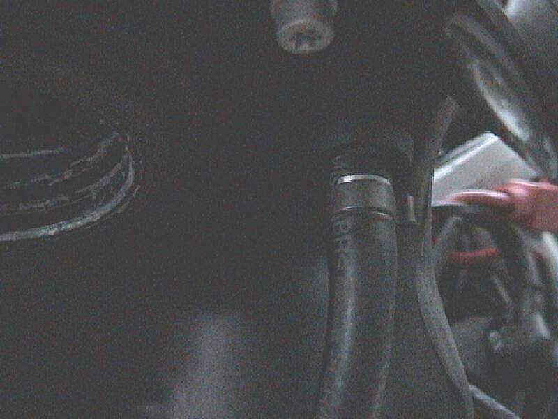
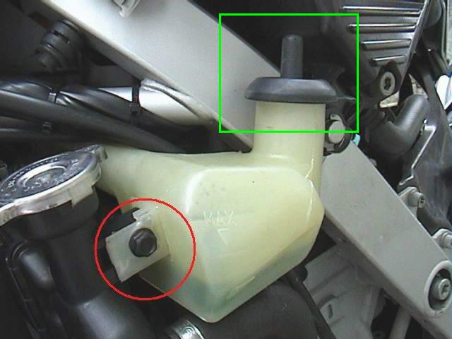
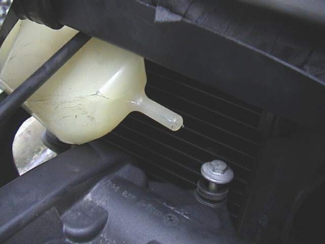
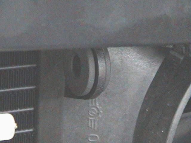
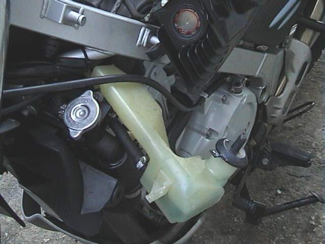
- Remove the one bolt on the
radiator expansion tank (Torx) on the left side under the
oil tank and pull its nib
out of out its
Grommet. If you like you can empty the coolant out of it into a milk
container or something. but it's OK sitting there. You might like to tie it up
with a bit of string, or let the
tank hang.
- The manual says to remove the fan and protect the inside of the
radiator with a piece of cardboard, but I didn't find that to be
necessary at all.
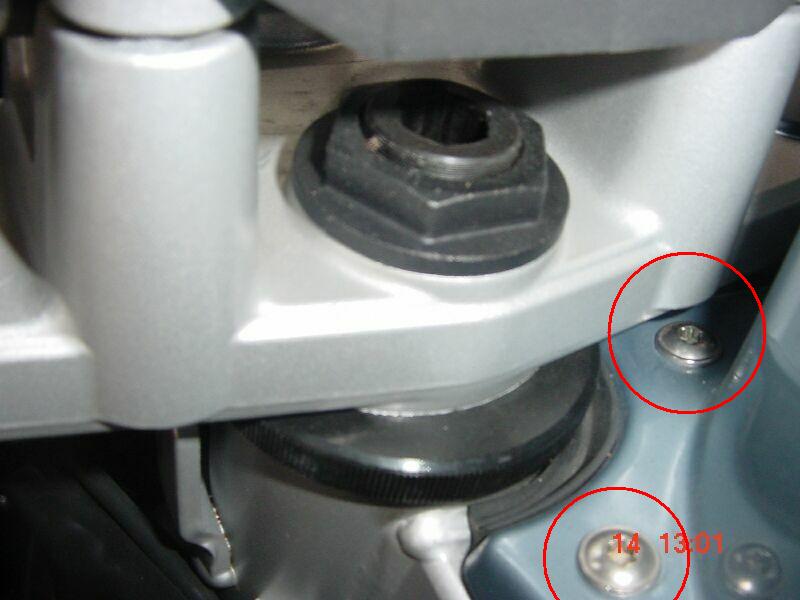
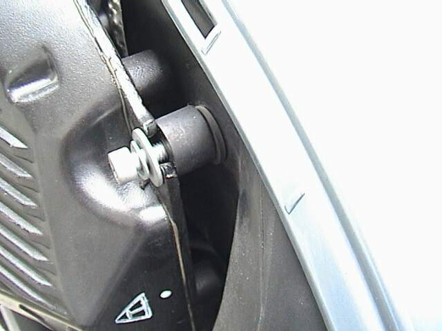
- The
oil tank needs to be
moved over to one side. The oil tank is attached to the bike at three
places: one is a bolt, the other two places are
C-clips. First dislodge the clips using a screwdriver.
Note that under each of the
C-clips is a
black washer, which
you should also remove, so as not to lose them. Then remove the uppermost
bolt, which
holds the tank against the air-box. Take care not to drop the
black plastic
spacer. Gently wiggle the Tank off the
Lugs. The oil tank should
now be free from
the frame.
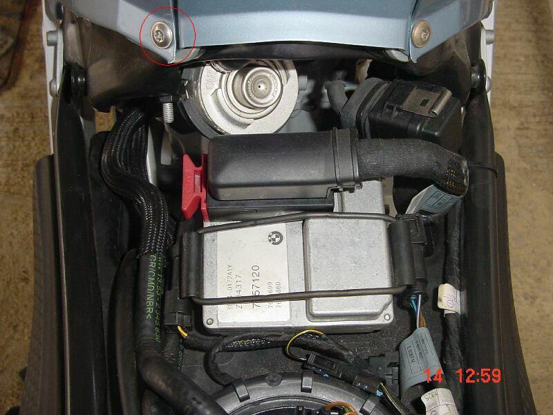
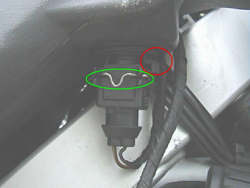
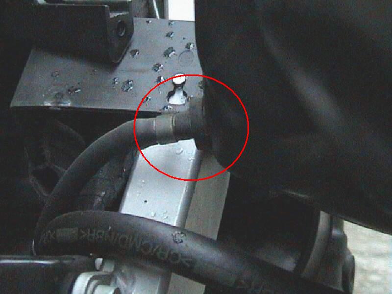
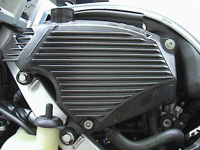
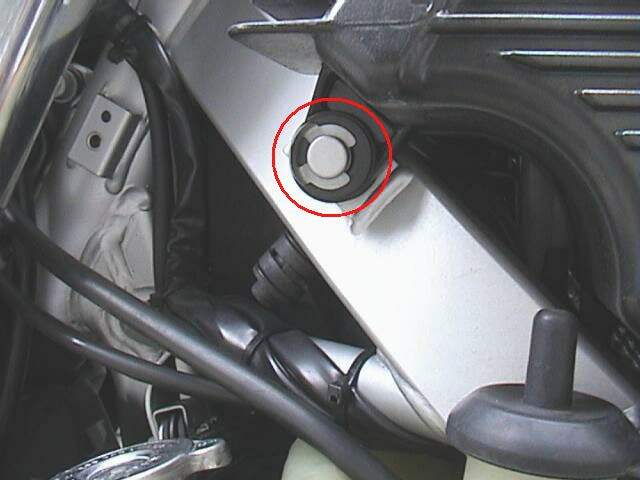
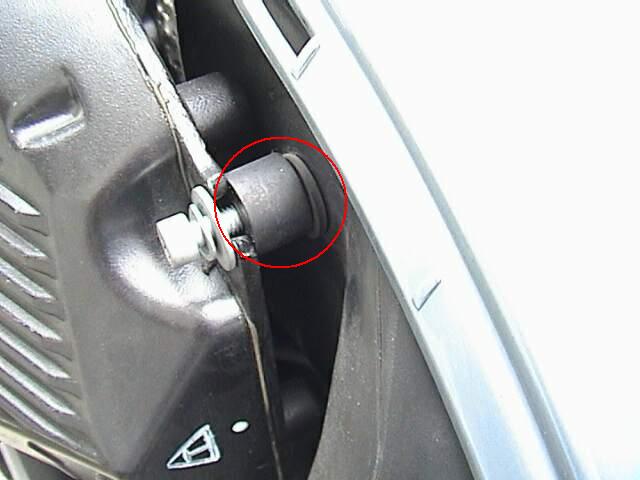
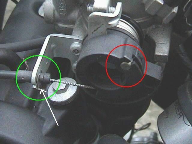
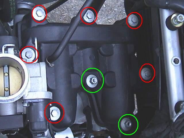
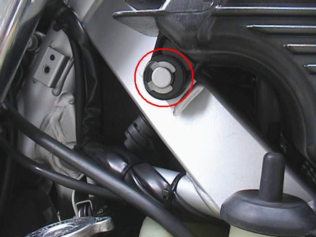
- Now you can see the top of the valve cover. Oh boy! Oh boy! Twist
the throttle grip and see what moves on the throttle body. You need to
remove the end of the cable from the black plastic thing (drum) that
moved when you twisted the throttle. It's on the
LHS of
the throttle body. Twist the
black plastic
drum (circled red) with your finger like the throttle did (to put
slack in the cable) and pull the end of the cable out. Put some grease on the
end of the needle-nose pliers and remove the clip (white arrow in green
circle) that holds the throttle cable
on its support (so you don't drop the clip). Pull the Cable out of the holder
and push it out of the way. [This is a good time to examine the throttle cable
for damage. Easier to replace it now if needed.]
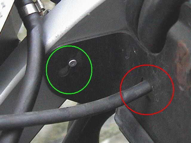
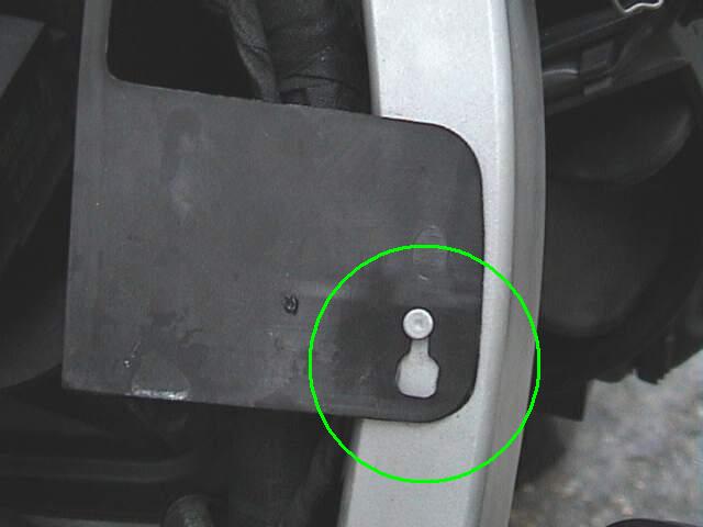
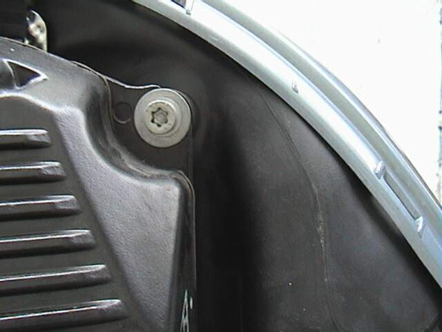
- There is a black plastic "wall" at the front of the valve
cover that the throttle cable goes through. Remove it. To do this slide
it out of the
small lugs (Green
Circle) welded to
the frame.
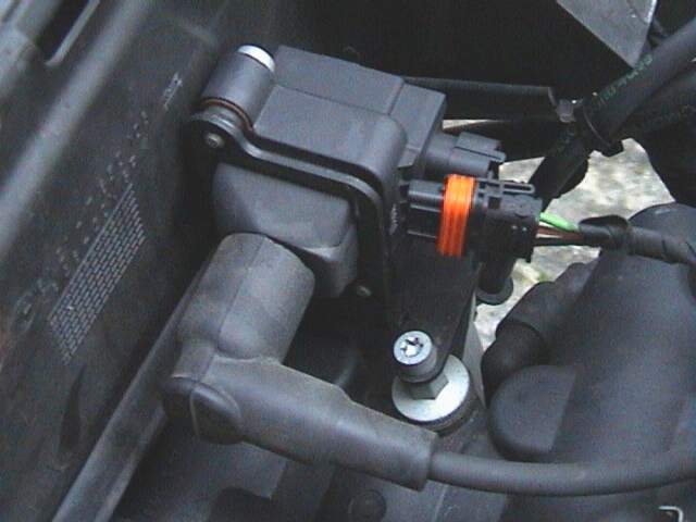
- Single Spark Models (pre 2004): Remove the spark plug wire
from the sparkplug and undo the two bolts (Only ONE shown as Red Circle,
other one as a the back) holding down the
coil at the other end of it. There's also a plastic connector (Green
Circle) going from the throttle body to the coil that needs to be
unclipped at the coil end. Remove the two Torx fasteners holding the
coil down and remove the coil.
Dual Spark Models (2004 on): Remove both spark plug caps.
Start with the outer one first and twist it clockwise. It can be a
little sticky removing the cap, but with persistance it will come off.
The inner plug cap twists anti-clockwise. Note which plug cap is on what
spark plug - this is important when re-installing.
- Loosen the
spark plug while
you're there, but don't remove it from the well. This allows the engine to
turn over without the piston developing pressure. (On dual spark
models you only need to loosen one spark plug). Dropping
anything into the cylinder is NOT a barrel of laughs!
- If you have the BMW OEM 12V accessory socket installed (OR you
have a dual spark model) you will have
to remove it in order to get the valve cover out. It should be on a
bracket sandwiched between the frame and the black metal bracket that
supports the air box. It is held in by
two Torx
bolts that have to be removed. The bracket and socket can be left
connected but moved aside.
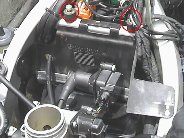
- Now use the 10mm socket, ratchet and extension to remove
all the bolts holding the
valve cover on. Two of these bolts (Green) have threads in the top of them for the
screws that hold the ignition coil on. You're going to remember where they go.
The front three get just the socket and ratchet, without the extension.
- With all the bolts out, jigger the cover off the cylinder head.
Despite what the manual says about replacing it the Valve Cover Gasket
is multiple times reusable and there's nothing to clean from the
cylinder head or cover as no sealant is used. Just take care with it. As
the Breather Hose from the top of the Valve Cover is attached to the Oil
Tank, you have to move both to the LHS of the bike simultaneously or if
you have a small hose clamp available you can remove the hose from the
top of the valve cover. This makes it a bit easier to get the cover on
and off the engine. Plug the line to the tank or some oil will dribble
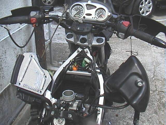
out of it. Either let them
hang from the hoses,
like this (but put a rag under any hard edges), or
tie a string around them
and support it from the frame.
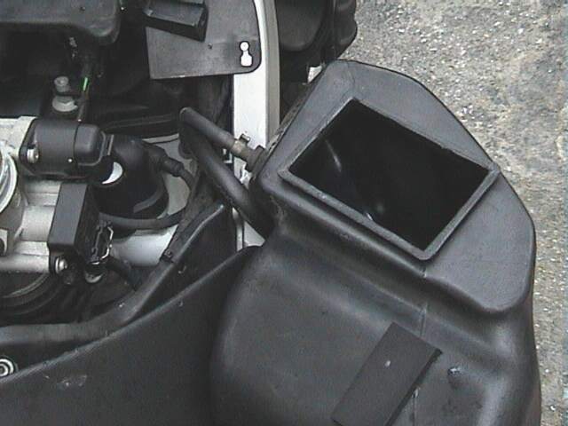
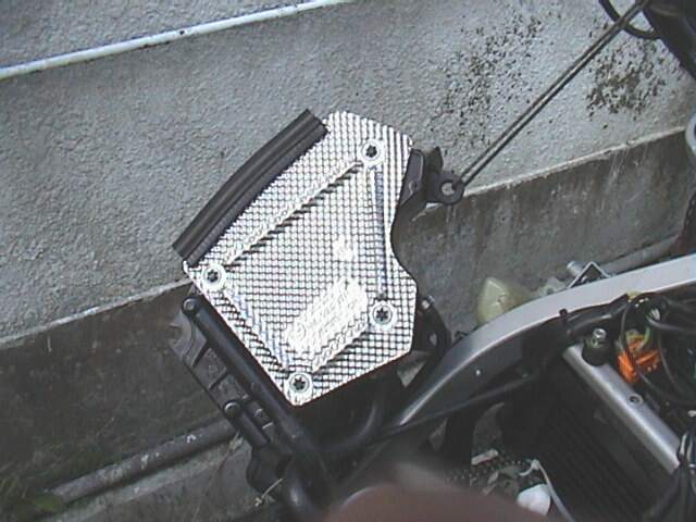
- So now
you have the Oil Tank/Cover on the LHS, Airbox Hanging off the RHS,
like this.
- Remove the
center plug on the
right side of the engine that covers the engine turning bolt (Allen wrench in
the tool kit.) It's soft plastic so be gentle. A coin or washer that JUST fits
is useful for this. Using the wrench, turn the engine so the two timing marks
on the cams point at each other. The
points of the cam lobes
on the two cam shafts should point AWAY from each other. If you want to be
sure the cams don't move during checking (although this is MUCH more important
during Shim Changing, insert the TDC Bolt). If you elect to just make sure the
marks are lined up, skip point 21.
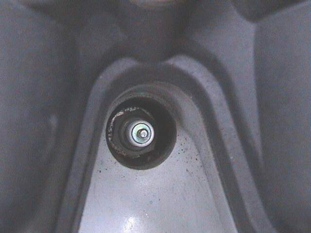
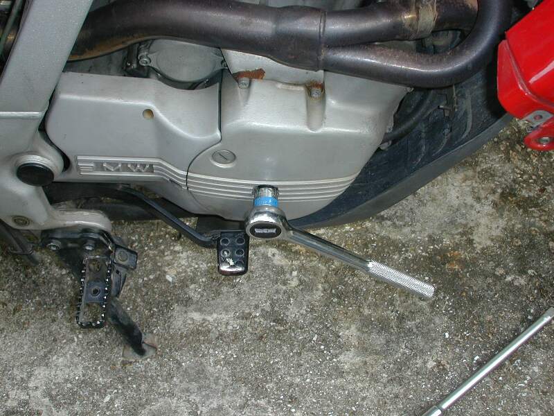
- To insert the TDC Bolt, remove the
Keeper Bolt
here, LHS of Engine, under LHS Engine Casing. Oil may run out of the opening.
Have the TDC bolt ready to reduce the spill. If no oil comes out then you can look into the TDC hole with a flashlight. Have a friend
(or just reach under the bike with one hand to the
spanner)
turn the engine over with the Allen wrench in the hole on the right side of
the engine while you watch for the slot in the crankshaft to go by, then
insert the TDC bolt and tighten it. You will know fairly well when you
expect the slot to be there, it should be when the Cam lobes are pointing
outwards. This can be done by feel instead. Thread the TDC bolt in lightly
till it hits the crank and them 'feel for the slot that will allow you to run
the TDC bolt a bit further. You're not going to forget to remove this bolt when you're finished,
are you? If the crank is hard to turn, you forgot to loosen the Spark Plug!
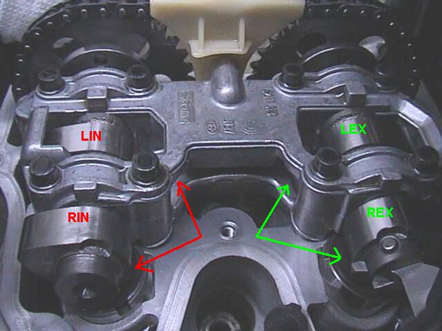
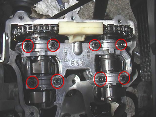
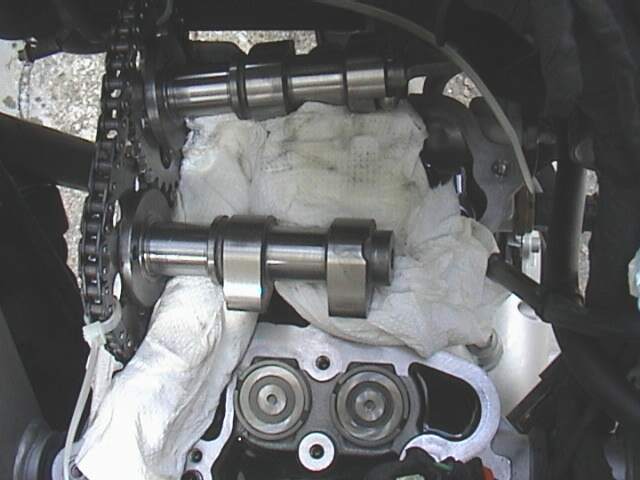
- Check the clearances with a feeler gauge, the Two RHS ones can be
accessed directly and the two LHS ones through the slots in the
"cut-out" on the RHS of the Cam Carrier. The intakes (Red in this
picture) are nearest the throttle body.
The exhausts (marked Green) are nearest the
exhaust pipe. I noticed in the service manual that the values for the
clearances change depending on what page you are on. (See Specifications for correct
values). The right side valves are
open to the feelers, but the left side valves have holes on the cam carriers
to check them. The slots are bigger than on the older models.
- If the valves need adjusting, the
procedures for the older model will help you through it. There are also some Tips for CHANGING
the shims on the GS/Dakar, below.
Reinstallation Sequence
Reinstallation is the reverse of the above (hate it when they say
that), so here's the sequence.
- 1 x Spark Plug
(OR two if you loosened both plugs on a dual spark model).
It's just plain easier to do this up now, rather than later for access
reasons. 20Nm or Follow the Directions on a New Spark Plug Packet.
- Valve Cover. 8 x 10mm Bolts.
Locations of Coil Bolts in Green. If the Breather hose it attached, you
will need to move the Oil Tank Closer to the Valve Cover. 10Nm. You can easily wiggle the throttle body back and forth on its rubber mounts
to replace the Valve Cover. The rubber is quite soft. If you removed the
breather hose, connect it now and secure with a new hose clamp.
- Single Spark Models: 2 x Spark Plug
Coil Bolts. Easier
to Install without everything else in the way. 9Nm. Plug back the
Injector to Coil Wire (in Green) in Photo.
- Reinsert the Spark Plug Cap(s) onto the Spark Plug. Push the cap(s)
on firmly. If you have a Dual Spark Model: the lighter colour
plug cap should be on the outside. However you SHOULD have noted this
when you took the caps off.
- If you have the 12V accessory socket (OR the dual spark
model), re-install it now.
- Thread the Throttle cable (Red Circle) through the Plastic
"Wall" and clip the "Wall" back in Place at the Two
Lugs. To do this slide them into the
small lugs (Green
Circle) welded to
the frame.
- Thread the Throttle Cable back onto the Throttle. Twist the
black plastic
drum (circled red) with your fingers (to put
slack in the cable) and put the end of the cable on the slot. THEN put the
cable in the holder and and reinsert the small C Clip. (White arrow in green
circle). Don't drop the clip!
- Fit the Battery Holder Plate and do up the two
10mm nuts.
This part includes a bracket that mates to the Airfilter housing.
- Fit the Airfilter Housing (rear part only) back on top of the
Throttle Body and into the holder attached to the "Wall" and
Press Downward ALL the way. There are three "bumps", you can
get past the first two easily, the third needs a bit more downward
pressure to push it onto the Throttle Body. Use Vaseline to fit it back
on if you need to. This also helps seal it. If you took the Airbox out
in one piece FIRST Slot the Snorkel Nib into its
Rubber Grommet just
under the RHS front fairing.
- Do up the the
Large Torx
Screws at the rear of the Airfilter Housing to 9Nm. With the Airbox
in Place you can affix the Oil Tank as there is something to affix it to.
- Push the Oil Tank back in Place onto the
two lugs and
reinstall the C-Clips.
Here's the other one.
Don't forget the Black
Plastic Washers go on first, then the Clips.
- Do up
the Oil tank to Airbox
Bolt. Don't forget the
Spacer and the
Washers. 9Nm.
- Fit the
nib of the Coolant
Tank in its Grommet,
insert the Bolt and Tighten "Hand Tight" to 2Nm. Check the Coolant
Level. See the Coolant FAQ for
Coolant Type to top up. Use distilled water to dilute.
- Plug the
Sensor Connection
back into the Snorkel and push the clip back in place.
- Fit the Electric Equipment Box
black plastic cover
Plate and do up the one bolt with the Torx wrench. 4Nm.
- Push the
Starter Relay back
on the Posts.
- Check if your Battery needs water. Refer the
Battery FAQ.
- Reinstall the Battery, Positive Terminal first. HOLD the Nut
behind the post with an open-ended spanner while you do up the bolt. If
you don't the VERY soft lead will rip across the smallish hole in the
post. Use a Short Phillips Screwdriver, then a Spanner to finish.
Tighten firmly, but NOT too much! It's SOFT. Some di-electric grease is
good here, on the posts. Do NOT Turn the Key in the ignition just
yet!
- Reinstall the
Plastic Overflow
Tube onto the Battery. Use a TyWrap on the vent hose to keep it from coming off and allowing acid to spill.
See this FAQ for why:
Battery Drain Tube - A Better Connector.
- If you took the Airbox out in two Parts, Clean the
Airfilter and Slot the
Snorkel Nib into the Rubber
Grommet just under the RHS front fairing. Fit the
Shroud and do up the
two
Torx Screws, Hand
Tight only. (A small bit of vaseline on the nib will help removing and
installing the airbox later).
- If you removed the vent line from the bottom of the Airfilter
housing, reinstall it now with a new hose clamp.
- Replace the Plastic Flywheel Access
center plug.
Just hand tight it OK. Coat the O-Ring before installation.
- Replace the Centre Faux Tank Panel. Do up the front
two screws
(Torx Screws) only. 3Nm, or just "hand tight".
- Remove the Oil Tank Filler cap and Replace the LHS Faux Tank Panel.
Do up the screw that was just
loosened, the
left-most screw that is exposed when the seat is
removed and the screw at the front
of the "gas tank". 3Nm, or just "hand tight".
- Replace the LHS Turn Signal.
Left. 4 Screws
3Nm, or just "hand tight".
- Repeat for the RHS Faux Tank and
right turn
Signal.
- Again, If you used the TDC Bolt, REMOVE
IT. The Keeper Bolt
Torque is 25Nm.
- Now go
to the correct Starting Procedure after a Battery Removal, for
re-initialisation of the
Motronic.
You're done!
Hints
-
You can easily wiggle the throttle body back and forth on its rubber mounts
to remove and replace the Valve Cover.
The rubber is quite soft. Ditto
the air intake housing.
-
Replacing the single use hose clamps with multi-use hose clamps is a good idea
while you're doing this work. The next time it will be that much quicker.
-
When replacing
the Airbox push it firmly on the top of it to seat it on the
throttle body while you watch from the side. A little Vaseline helps.
-
The battery-post nuts have a little
shelf they sit on while you turn the bolts with a Short Philips screw driver
(or spanner) and
hold the nuts on the shelf with your finger. Using a di-electric grease on the
terminals will prevent corrosion. Make sure these are properly tight. Loose
battery connections lead to all kinds of odd running problems.
-
I didn't find it necessary to
remove the fan, but you might want to. Check if your battery needs water.
Section 3: GS Valve Shim Adjustment
by Paul & Kristian #562
Introduction-Adjustment
Basically the adjustment procedure is the same for the Classic and the
GS, however there are a few "Gotcha's" to watch out for.
- The pointers below assume you have read the Valve Shim Change
FAQ for the Classic.
- It is highly recommended you read it.
- CAUTION: If your bike is equipped with
ABS brakes you face an additional challenge doing this
procedure. The ABS pump
location makes removal of this bolt quite difficult.
Tools-Adjustment
There are three tools you can make to facilitate the job. You need a
bench grinder to make them.
- The first is made from a thin finishing nail, the kind with no head.
You want to grind or file a flat, concave point on the end as thin as
possible. This is used to pry off the shim from the lifter. Oil suction
holds it on very tight. You need to shove this tool between the shim and
the lifter at one of the two notches in the lifter. A pointy thin
knife also works well.
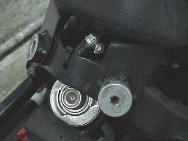
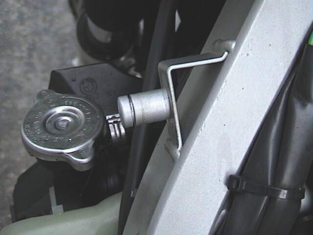
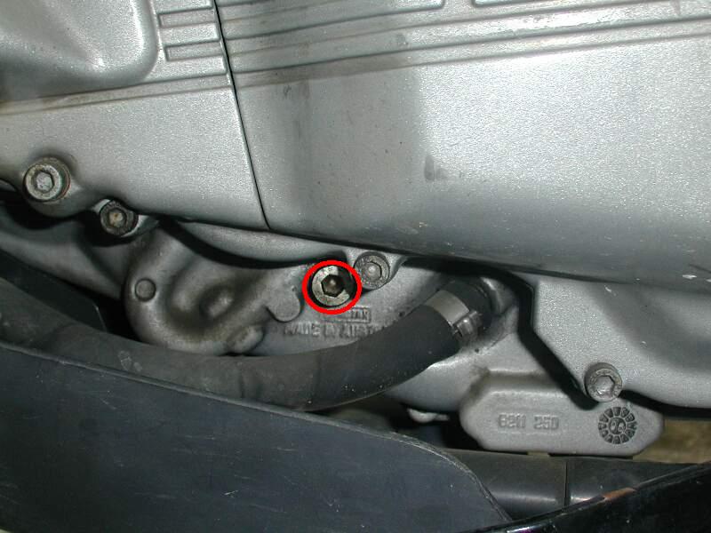
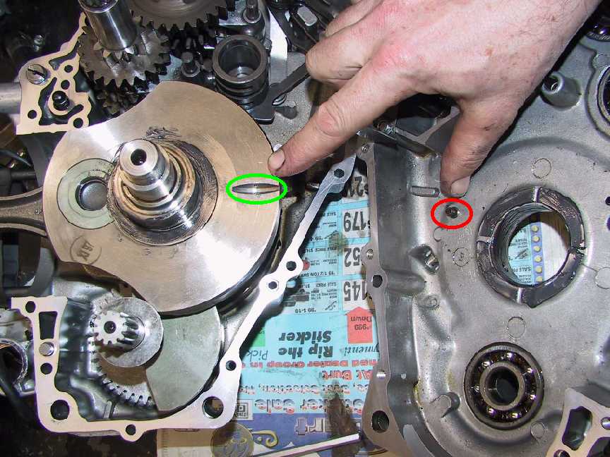
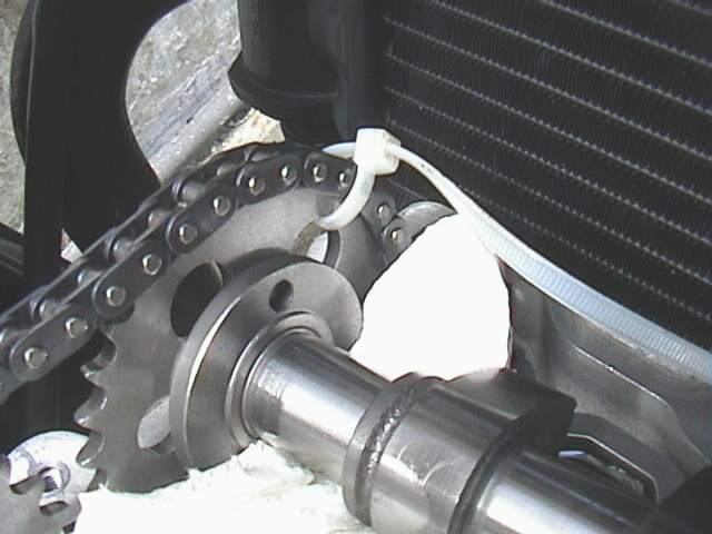
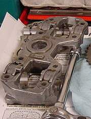
- You may need a tool to remove the 22mm bolt that goes over the
hydraulic chain adjuster (see alternative method below). From the picture in
the FAQ it appears that this bolt is easy to get at on the Classic. Not
so on the GS/Dakar - especially if you have ABS! This is the Photo for
the GS/Dakar.
Option 1. Buy a Short 22mm Socket with a short extension or a LONG,
preferably 6 point, 22mm Socket.
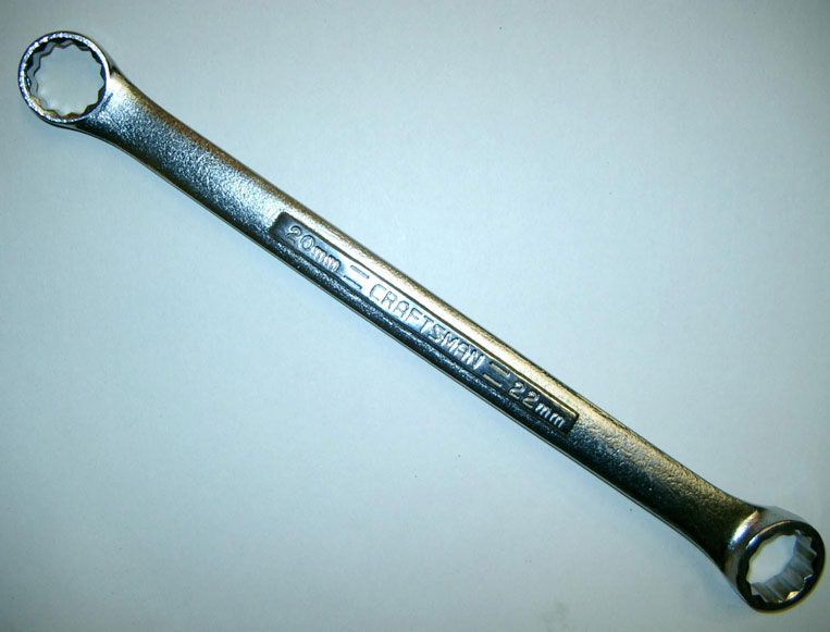
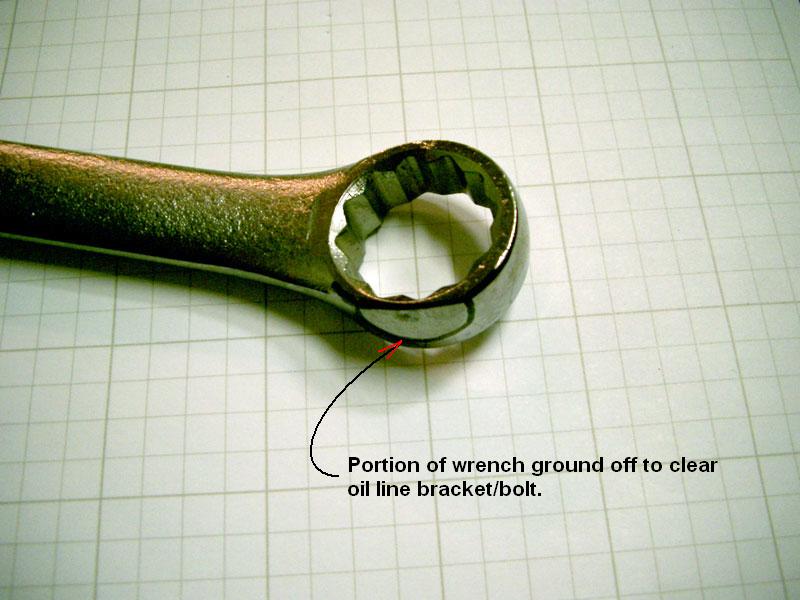
Option 2. Buy a 22mm open end/box end wrench from Sears. Using the bench grinder, grind
off the box end leaving about a one inch stub on it. Refer Below for how Paul
loosened the Bolt using this Option.
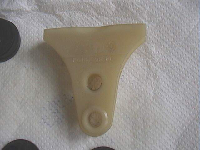
- The third tool you can make (or buy at BMW for cheap if they have
it) is a TDC bolt. There is a
plug bolt on the left lower side of the engine that you
remove and insert the
TDC bolt which goes
in a slot in the crankshaft, locking the engine for camshaft
removal/installation. Buy an M8X1.25 bolt about 40mm long at the store AND get
a nut that fits it. Screw the nut on the bolt and make it look like the
picture in le FAQ. (i.e. a 45 degree angle not to a point on the end) using
the bench grinder. With the point ground on the bolt remove the nut from the
bolt (you'll need to clamp the head of the bolt in a vice and turn the nut off
with a wrench) Grinding messes up the threads on the end and running the nut
back and forth restores them. So make sure the nut is on before you start
grinding! Refer the TDC Bolt FAQ for
further information.
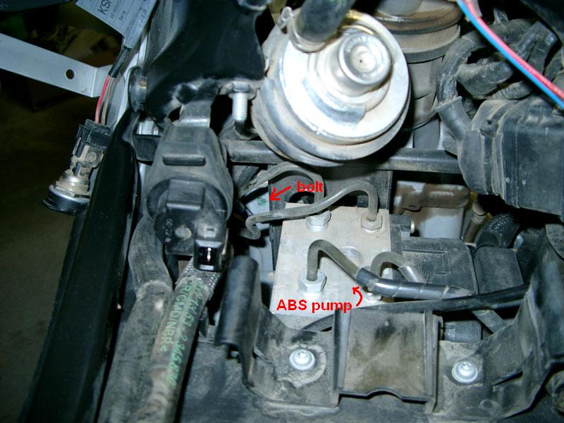
- NOTE - For ABS equipped bikes!
Your bike's ABS system includes a pump and other devices to function.
BMW choose to locate this
pump directly behind the engine cylinder and in front of the under
seat fuel tank. (the bolt is partially visible and has a green mark on
it). There are hard lines leading to the brake system components at the
front and rear of the bike. Two of the lines exit the pump and cross
very close behind the 22mm bolt that retains the cam chain tension
adjuster. The method described for a non-ABS bike will not work for you.
There is no access to the 22mm bolt from above and behind as is
recommended for non-ABS bikes.
If you have ABS you have two options to access the 22mm bolt, or a
further third option which does not require access to the 22mm bolt.
Here are four ways that have been used by others to access the bolt:
- Completely removed the sub-frame of the bike. You are on your
own for now as I'm not aware of an FAQ for this. Additionally,
you will have to disconnect the lines to the ABS pump to move
it. This may introduce air into the system which MAY require the
BMW MoDiTeC unit to purge the system. Some members have reported
doing this without the MoDiTeC with no problems. You'll have to
decide if you want to take that chance.
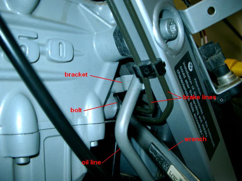
- The other method involves using a slightly modified
12
point 22mm box end wrench and working from the LHS of the
bike through a
small
area between the frame and an oil return line. This method
requires long fingers and some strength to reinstall the bolt.
It is very hard to reach up through this small area but it is
possible. I did it using my left hand, bolt held with my thumb
and middle finger, palm facing aft (towards the rear of the
bike). You must use a 12 point type wrench because the throw of
the wrench is very limited. I ground the edge of the
wrench to
get it to clear a bracket
on the oil return line that gets in the way. The other issue
with this method is that you will not be able to use a torque
wrench to tighten the bolt. DO NOT loosen the this bolt on an
ABS bike until you have determined how you will reinstall it.
Experiment reaching in with your hand and with the wrench before
cracking it loose. The bolt is under very light tension so that
is not a problem.
- What I ended up doing was to pray metal break lines attached to
ABS unit (very carefully) so that I moved them away from each
other and made space for a socket and extension to get through.
I used a flexible joint that comes with a rachet and socket set.
After making the opening between break lines there is no problem
geting to the tensioner bolt from under the seat. sunio
- Actually, I finished the 12K service yesterday. The cam chain
tensioner problem was solved with a stubby "professional grade"
Craftsman box & open-end wrench. It allowed enough room to
easily tighten the bolt. I wasn't able to use a torque wrench
but I am confident this is not a problem. Just to be on the safe
side though, I did mark it with a sharpy pen to see if there is
any movement JC12 #1484
Probably best option for ABS bikes is NOT to remove the
22mm bolt at all. See the Alternative
Method.
Preparation-Adjustment
If you have the Dakar I suggest putting a block of 2 X 4 under the
Sidestand to level the bike as much as possible. Oil will run out when you
remove the plug bolt otherwise. Not much runs out, but if you have the TDC
Bolt ready, you can swap the bolts fairly quickly.
Procedure 1: Adjustment
- Follow the procedures for the Valve Check up to Point 22 in the
above FAQ, ensuring you DO put in the TDC Bolt & Re-record the
Clearances FIRST.
- Remove the Chain Tensioner Bolt:
Option 1: Kristian #562
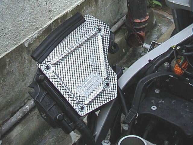
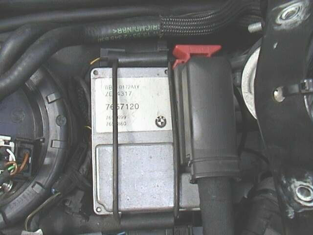
Take the
Rubber Band off the
Motronic and move it to the
RHS of the bike
to give yourself a bit of Room to
Access the Bolt.
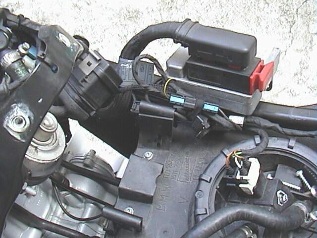
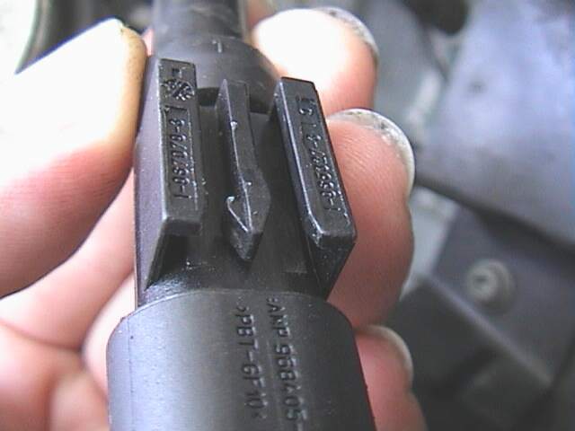
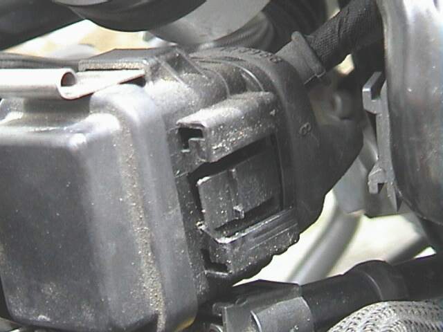
Disengage the
ABS/Speedo
Sensor Cable so you don't break it. First simply squeeze the rear part of
the Connection and pull the Electrical Connection apart. Then using a Small
Screwdriver, press down GENTLY on the
middle tab
(of these three) and disengage the Connection to the
Plastic Holder,
pushing it toward the front of the bike. Reconnect it and move it over to the
RHS of the bike out of the way.
Unclip the Fuel Lines from their keepers just to
the left of where the
ABS/Speedo
Sensor Cable was and move them to the left a little bit.
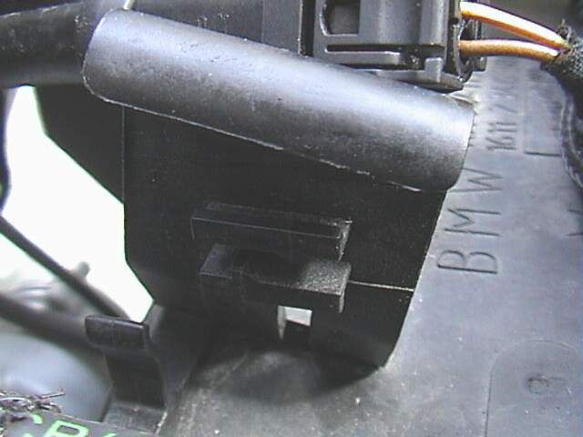
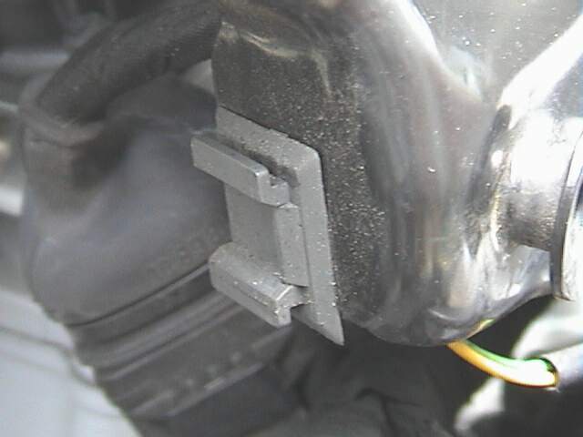
Unclip the little
Black
Box that was just to the right and to the front of the Motronic. Using a
Small Screwdriver, press down GENTLY on the middle tab (of these three)
and disengage the Connection to the
Plastic
Holder, pulling it gently toward the RHS of the bike.
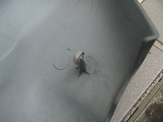
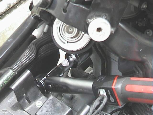
Using a 22mm Socket with a SHORT extension, you
should be able to access the bolt enough to undo it and to later
Torque it
up again.
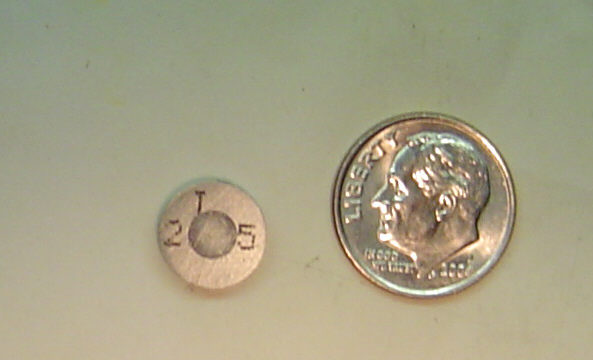
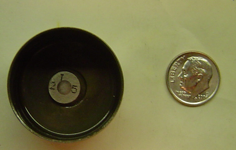
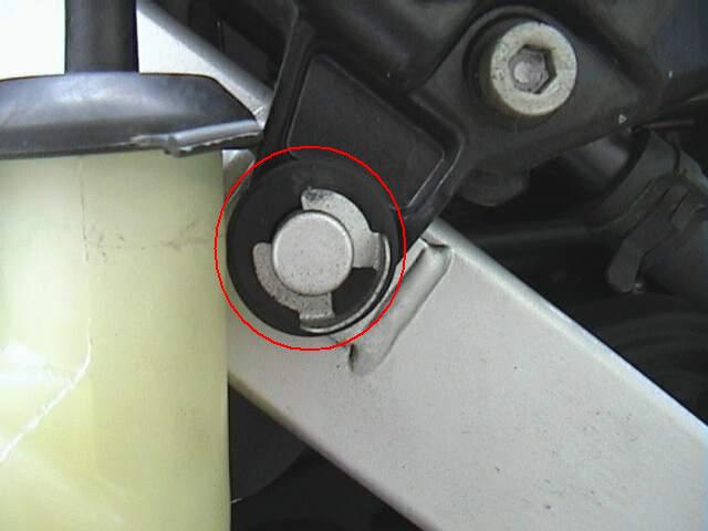
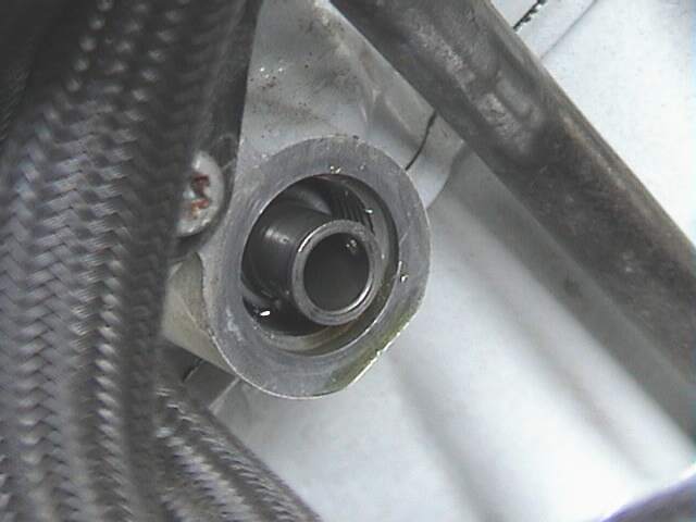
When it's undone you'll see
this.
You don't have to remove it, but if you don't you might like to put a bit of
tape over it to ensure it doesn't fall out. It's a little Silver Cylinder that
MUST be kept clean and free from scratches.
Option 2: Paul
To loosen the bolt put
the 22mm open end/box end wrench on the bolt, stub end down.
I used a six inch extension (3/8" drive) and put
the square hole in it on the end of the stub. (from the left side of the bike)
- Then I hit it with a hammer to loosen the bolt. To tighten the
bolt I put the tool on the bolt as above, but from the right side of the
bike I stuck a large long blade screwdriver through the cables wiring, etc
to rest it on the stub and hit the screwdriver with the hammer again.
Tough spot!
- Once the bolt is loose you need girly hands to get your fingers
into the tight space to loosen/tighten the bolt. The toughest part of the
valve adjustment is dealing with this bolt!
ABS equipped option 3: BradG#1002 (option 'B' from above under Tools-Adjustment
note 4)
- Put a piece of tape on the top of the metal oil return line to
protect the finish from the wrench.
- Insert the modified 22mm box end from LHS and crack it loose.
Undo it the rest of the way with your fingers. Be careful not
to drop it or the crush washer.
ABS equipped option 4: See the
Alternative Method.
- Swapping Shims
- STUFF SOME RAGS IN ALL PLACES,
ESPECIALLY AROUND THE CAM CHAIN, WHERE SMALL BITS, SHIMS,
TOOLS ETC CAN FALL DOWN!
- If you have a 2004 or later model, the shims are under
the buckets.
- With the Chain Tensioner Bolt out, the cam chain will now be
slack, but you still won't be able to lift up far enough to
get to the Shims until you undo the 8
Cam Carrier Bolts. (5mm Allen Key).
- Unlike the Classic, you cannot remove the front guide rail
far enough out with the Cams still locked into the Cam
Carrier, before it hits the radiator, so you can't remove it
unless you remove the radiator. So I recommend forget that
and undo the T-Bone Guide, unless you are just changing the
RHS Shims.
- It is MUCH easier to get the shims in and out if you remove
the Cam Carrier completely, but you can try and lift up the
Cams in the Cam Carrier, using the slack in the Chain from
the Loosened Tensioner. It is NOT as slack as the Classic,
due to that front guard not being able to be removed.
- The zip
tie procedure in the Classic FAQ works well for the
shims on the right side of the bike, but it's extremely
difficult, although not impossible, to get the ones out
nearest the cam chain. If you need to get at the latter
shims I suggest removing the cams for a first timer. The
cams go in and out easier than you might think, especially
with that TDC bolt in place.
- If it is just the RHS Shims you need to change, leave the
Cams in the Carrier, use a bit of wood or rubber to hold the
Cams as high as possible and using your knife or Nail Tool
(see above), pry up the Shim and slide out with a pair of
tweezers. Replace with the new Shim.
- It is a good idea to wet everything with oil (both sides of
the shims) during reassembly.
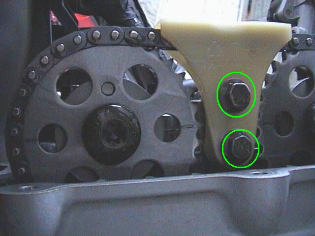
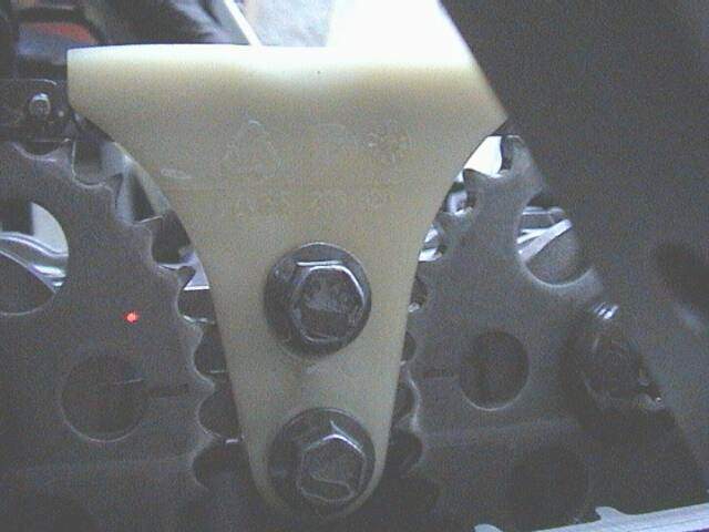
Procedure 2: Cam Carrier Removal
- Remove the two ten mm bolts holding the "T bone"
on the left side of the carrier. Remove the white plastic
T bone1.
T bone2.
T bone3.
T bone4.
T bone5.
T bone6. It is
easier to remove these FIRST, before undoing the eight 5mm Allen bolts holding
the cam/cam carrier on, however if you've already undone them, you can
undo the Two T-bone bolts afterwards, although you might like to get someone
to just hold the Cam carrier flat while undo those two bolts. Prise apart the
T-bone at the lower end and lift it up over the chain.
| Hint for removing the cam carrier |
|---|
| A word of caution---Even though I had a rag stuffed down in beside the cam chain, [the washer from the cam carrier bolt] still made it's way down there. I would advise not pulling the bolts out of the cam carrier but loosen them until they are free of the head and then pull the entire cam carrier and bolts out as one unit. Return them the same way. Maybe it will save you this pleasure. jagdkampf #1761 |
- Then remove the eight 5mm Allen
Cam Carrier Bolts
holding the cam/cam carrier on. The
cam carrier
is split in two and acts as the bearings for the cam. Remove the top half
of the carrier. Start with the rearmost (intake) cam and lift it up and
towards the front cam. The chain should be loose enough to do this. Then
remove the exhaust (front) cam moving it up and back. Be ready with a zip tie,
string or piece of copper wire to hold the cam chain up in the air. Tie it to
one of the cables above it or the handlebars. Now remove the bottom half of
the cam carrier. It's held in position by two steel locating pins on the left
side of the head. Your
cams are now exposed (woohoo) That wasn't hard was it, and now it's much
easier to deal with the
shims!
- Use the
sharpened nail to get the shims out. A small screwdriver won't work especially
with the cams/cam carrier in place, but a thin sharp point knife will. There are two little notches on each side
of the lifter to pry at the shim. Spin the Bucket around until you get one of
the notches close to you and insert the nail straight at the line between
the lifter and the shim to break the suction. Then lift the shim up and out.
Imagine doing this with the cams in there, especially the ones near the chain.
(it's possible) Put the new shims in before installing the cams!
-
Werner #547 notes: The rag works well, but you can be doubly sure
(you don't flick a shim into the Cam Chain Well) by lifting out the whole cup
(bucket) holding the disk. (Do one at a time, so as not to mix them up during
reassembly.) Then you can sit down on your barstool and remove the little disk
with your pointed nail while sucking on a tall bubbly. [ed. this is highly
recommended if you've got the cams out of the way]
- Clean the holes in the Cam Carrier for the T-Piece Bolts.
Procedure 3: Cam Carrier Installation
- To
install, clean everything really well and place the parts on clean
newspaper/rags. Spray carb cleaner is good for this. Wipe down the surface of
the head with a clean rag then wipe it down with your clean fingers to remove
all traces of dirt/oil. (human skin is the best tool to clean parts) Put the
lower half of the cam carrier on its two steel pins. (both are on the left
side of the head). Oil the Bearings and the little grooves liberally with
Clean Oil.
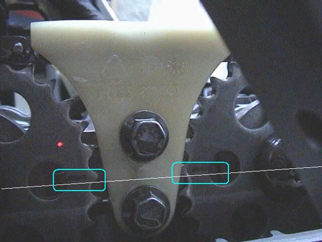
- Holding the cam chain up in the air, cut the tie securing
it. Get the exhaust (front) cam in your other hand and wrap the chain around
it while you seat the cam in the carrier. You want the lobes of the cam to
point to the front of the bike and the line on the gear to be level with the
top of the head. OK the cam is in but the lines aren't level? Lift the cam up,
remove it from the chain and turn it one link of the chain in the direction
you want it to go. It'll take a few tries but its not hard. When the line is
level get the intake cam and point the lobes to the rear of the bike. Slide it
under the chain and into the carrier. Repeat as above until the little lines point at
each other like the picture.
TEST it again by pushing in the
Chain
Tensioner Barrel by hand. The TDC bolt is still in right? The Cam Lobes
should look like this,
when finished.
You did it!
- Oil the Bearings again, liberally. Put
the top of the carrier on the cam and bolt it in place with the eight
Allen bolts. Check to make sure there is a washer under each bolt when you
have them all on. Snug all the bolts just a little in a crisscross pattern
(but do not torque them down).
- Then install the
T bone and the two bolts that hold it
on. The Threads should be CLEAN and coated with Loctite 243 before you screw
them in. Torque to 10Nm. (The bottom bolt first)
- Now torque the cam carrier down in a crisscross pattern, working
from the 4 inner bolts to the 4 outer ones. Then following the pattern
tighten them a little more. Check the Cams can swivel easily in their
bearings. Then tighten a little more until you reach the torque value of
10Nm.
- Install
the bolt over the chain tensioner. Torque is 40Nm, new Aluminium Crush
Washer. (Go have a beer first and call your mother to tell her you just
adjusted your valves.) Getting that bolt in is the hardest part. If you have
ABS and opted for Brad's method you must start and hand tighten, then tighten
as best you can with the box end wrench from the
LHS.
- Take out the TDC locating bolt and re-install the TDC
Keeper Bolt.
Torque is 25Nm. Use a new Copper Crush Washer (But you can re-use the
old one once), Torque is 25Nm.
- After installing new shims and tightening the cam
carriers/tensioner, but before installing the valve cover, it's worth
and rotating the engine by hand a few times.
- Turn the engine over BY HAND, with the sparkplug out, SLOWLY, using your
spanner in
the Flywheel. If nothing jams up you "did good".
- This is the important part, to spin the
motor around at least two revolutions, maybe four, and measure again before
you button it back up. (The oil film will take up some of the clearance until
you spin the motor to squish it out.)
It is a REALLY good idea to re-measure the clearances also, just to make sure.
It's better than finding out at start-up that it was re-assembled 180 degrees
off.
- Do not worry if they are not exactly what you calculated! Close
but not exact. The difference is mostly in the Oil Film.
Reinstallation to the Point you would be if you just did a Valve Check
If you chose option #2 or #3 for removing the cam
chain bolt then you can probably skip to v. because you didn't really need to
remove the items referred to in i-iv.
- Put the Fuel Lines back in their clips.
- Put the
ABS/Speedo
Sensor Cable back in its clip.
- Put the
Rubber Band back on
the Motronic.
- Put the little
Black Box that was just to the right and to the front of the Motronic back
in its clip.
- Refer above
Re-installation Sequence
(Valve Check) to finish off.
- If you zip-tied the cam chain to the cams, don't worry if when
you put the Cams back, the timing marks are out, it is possible to
lower the chain far enough so that it disengages from the drive gear
at the bottom end (i.e. in the Crankcase) and goes along one tooth,
as long as you STILL have the TDC bolt in place. You can simply cut
the zip ties and put the Cams back WITH the marks on the
Cam
Wheels aligned WITH the lobes outward.
Alternative Method / ABS Bikes
The following method allows you to do a shim change without
removing the cam chain tensioner. This is especially useful if you have a
bike with ABS - since the ABS pump is in the way. This section is based on
feedback from ThreePly, dinskeep and the BMW GS manual (pictures by
dinskeep).
| Short and Sweet Version |
|---|
|
Remove the intake cam first. Grab the cam gear with one hand and
the cam shaft at the opposite end with your other hand. Lift up and push
towards the exhaust cam (front of the bike). The cam chain has enough flex
in it, even with the tensioner bolt in, to allow you to get it out.
The method described is also found in the BMW Service Manual (that
I have at least):
- Tie the cam chain to both sprockets (so you do not loose the
timing)
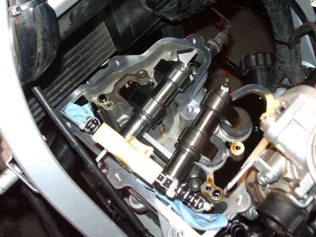
- Remove the top of the cam carrier
- Remove the intake camshaft (In the picture it looks like it has
been place forward and to the RHS of the bike)
- Remove the exhaust camshaft (Again, in the picture it looks like
it has been place forward and to the RHS of the bike)
(See below for the longer detailed version)
|
Starting with the valve cover off:
- Bring engine to TDC and put in TDC bolt
- Ziptie chain to cam sprockets, as Flash describes
- Do not remove cam chain tensioner
- Remove
cam
carrier bolts, top carrier, chain guide
- Pull intake cam off of lower carrier, then exhaust cam <-
this order is important! see
this pic
- Remove lower cam carrier
- Remove buckets and replace shims as needed
- Replace buckets
- Clean and replace lower cam carrier. Lube with fresh oil
(the above is mostly the same as DVD and current FAQ's, with exception
of cam chain tensioner)
- Put exhaust cam back into carrier, then intake cam <- this order is important and REVERSE of removal!
- Check time. If it's lined up, good, put it all back together.
If you loose timing:
- Cut all zip ties.
- Take intake cam out of carrier, leave exhaust cam in.
- This should give you some slack (which you otherwise don't have,
because the tensioner is still in) to pull the chain off the exhaust cam
and put it in proper place - marks horizontal, lobe outward (front of
bike).
- Pull any chain slack between the exhaust cam and the bottom, ziptie
the chain to the exhaust cam sprocket. From here on the exhaust cam should
not move, and the chain should not leave the exhaust cam sprocket.
- Make a guess as to where the intake cam should be aligned on the
chain and put the intake cam in the carrier.
- See how the intake cam is aligned - try to estimate how many teeth
you're off, if any.
- If the intake cam is not aligned, ziptie the chain to the intake
cam, pull the cam out, and use the slack to get part of the chain in the
right spot on the intake cam sprocket. Ziptie the chain in that spot and
cut the previous ziptie.
- Put the intake cam back in the carrier and see if you guessed
right. If you're still off, repeat the last two steps (6 and 7) until you
get it right.
Other Hints and Tips
- I downloaded a video (Not the Chain Gang maintenance DVDs) from
someone on this site about 6 months ago that showed how to do this. Let me
know if you'd like me to send it to you. In the video it looked so easy
sliding the cam right out but it was not easy for me at first. I struggled
mightily trying to overcome the chain tension and the "oil vacuum". I
almost gave up and started to look at how to get the tensioner bolt out as
well as other options (see below). I came back the next day and gave it
one more try and it slid right out. Every time after that it (changing,
rechecking, rechanging) was rather easy.
- It was probably a combination of knowing it COULD be done as well as
knowing the correct motion. The point of all of this is - It can be done,
don't give up, and don't tear apart your bike trying to get to the
tensioner bolt.
- Other Options:
- This one came from the local wrench. It was just an idea, he's
never actually done it. Remove the cam gear from the cam shaft. It is a
T50 Torx and requires 45 ft/lbs of torque to reinstall. I actually started
to try this before having success with the above procedure. The reason I
stopped is because that torx is in there really tight and until you break
it free, all the force you apply is trying to turn the cam which in turn
means you are applying that force to your TDC bolt / flywheel setup. I
didn't want to risk breaking off my TDC bolt so I stopped.
- I'm not real sure about this one, just an idea. Can you just
loosen but not remove tensioner bolt? Obviously you will not be able to
replace the crush washer unless you were to remove it completely but crush
washers should be reusable once.
- One note about the video: There is some erroneous info in this
video. It says that the timing marks will ALWAYS be a half tooth off when
at TDC. From my own experience, talking to the local wrench and the
inmates I found this to not be true (See
http://www.f650.com/Forums/ShowPost.aspx?PostID=104875).
- [To fix any lost timing] On the DVD, Flash moves the chain without
removing the cams because the tensioner is out. So, I'd say that is
different than what I did, but it's the same basic idea - see where you're
at, move the chain a tooth or two at a time, and then see where you're at.
The exhaust cam was easy, but it took a number of tries with the intake
cam to get it right.
- Don't forget to rotate the engine a couple of times and re-check
the alignment before you put everything back together.
Section 4: Other Things
Valve Clearance Feedback
-
For those with new
GSss who have not fiddled with them yet, be careful removing the two halves of
the faux gas tank. The lower edge has a point that fits into a rubber grommet
on the chassis and will break if you force it especially if its cold outside.
When you get it off hopefully in warm weather grease the rubber grommet with
vasoline before assembly and it will go on and off much easier. The clearances
on the valves were 004 and 007 for the intakes and 009 and 011 for the
exhausts. Never seen valve clearance out that much on a shimmed valve engine
so if you were thinking of letting the clearances go think again.
What are the dimentions of my shims?
As noted at the top of this FAQ, there are two different shim sizes.
The pre-dual spark FI models (Classic, ST and single spark FI models) have
a shim over the bucket. The dual spark FI models have a shim under
bucket. Note: Some parts fiches can be confusing and have diagrams of
shims over buckets for the dual spark FI models. The following are the
part numbers (please check with your supplier to ensure you get the
correct shims).
For a lengthy discussion on the shim sizes, check
this
thread
| | Shim OVER bucket |
Shim UNDER bucket |
|---|
| Diameter | 29mm | 10mm |
|---|
| 2.00mm | 11321460147 | nil
|
|---|
| 2.05mm | 11321460148 | nil
|
|---|
| 2.10mm | 11321460149 | nil
|
|---|
| 2.15mm | 11321460150 | nil
|
|---|
| 2.20mm | 11321460151 | nil
|
|---|
| 2.25mm | 11321460152 | nil
|
|---|
| 2.30mm | 11321460153 | 11327675540
|
|---|
| 2.35mm | 11321460154 | 11327675542
|
|---|
| 2.40mm | 11321460155 | 11327675707
|
|---|
| 2.45mm | 11321460156 | 11327675709
|
|---|
| 2.50mm | 11321460157 | 11327675711
|
|---|
| 2.55mm | 11321460158 | 11327675713
|
|---|
| 2.60mm | 11321460159 | 11327675715
|
|---|
| 2.65mm | 11321460160 | 11327675717
|
|---|
| 2.70mm | 11321460161 | 11327675719
|
|---|
| 2.75mm | 11321460162 | 11327675777
|
|---|
| 2.80mm | 11321460163 | 11327675779
|
|---|
| 2.85mm | 11321460164 | 11327675781
|
|---|
| 2.90mm | 11321460165 | 11327675783
|
|---|
| 2.95mm | 11321460166 | 11327675785
|
|---|
| 3.00mm | 11321460167 | 11327675787
|
|---|
CS Head Removal
- I need to know whether the repair procedure for removing/installing the cylinder head for an '05 F650 CS ABS (procedure no. 1112116) as set forth in the current Rep-ROM repair manual (release date 03/2004) is correct. Specifically, I need to know whether you really have to remove the ABS modulator pump and remove the rear subframe in order to accomplish the procedure. Zeke BBG#26
- You don't need to remove the ABS pump or rear subframe to remove the head. How do I know? 'Cause I did it. I drilled an access hole in the battery holder to gain access to the cam chain tensioner bolt and vent screw. Worked like a charm. Zeke BBG#26
The time I was the most nervous was when I backed
the bike out into the driveway to fire it up.
I tried to remember if there was anything I had forgotten before pressing
the button,
but I couldn't think of anything. So I pushed start and it fired up
immediately -
and purred like a kitten. -- JC12 #1484 after a 12k service
