Classic Valve Shim Check FAQ
by Kristian #562, Flash #412
Additional comments by Shank, Paul in NJ,
Please read the Disclaimer before attempting
any work in this FAQ.
Last Updated: Sunday 22 October 2006, Winter #1935
Other Relevant FAQs:
Introduction
This FAQ is
only for CHECKING the Valve Clearances. For performing a Valve Shim Change once you
have ascertained they ARE out of spec refer
The Valve SHIM CHANGE FAQThis is a simple job you can do yourself
and save some money doing it. BMW recommend the Valve Clearances are checked
every 10,000km or about 6000 miles. You should only change the shims when they
are OUT of spec. If you are new to all this or have additional questions, it is
recommended you also read the Valve Misc. FAQ.
Specifications
The "Classic" BMW Manual specifies:
0.10mm ~ 0.15mm or 0.004<94> ~ 0.006"
for Both Intake & Exhaust
For specifications for the Fuel Injected bikes, see the The GS/Dakar Valve Shim Check FAQ.
| Testing The Gap |
|---|
|
The idea is that the gap should be anywhere between or EQUAL to the
specs. The large feeler gauge should NOT fit between the cam and shim.
(OK, a REALLY tight fit is probably acceptable.) The small gauge MUST fit
between the cam and shim. (If it doesn't... you are likely on your way to
a burned valve.) The ACTUAL GAP will be anything in between. Since the
shims only come in 0.05 mm (0.002") increments, there is only ONE
shim that will put you within the proper range of adjustment. I don't
generally do all the math. I just stick the feeler gauges in and the
small better go and the large better not go. If that isn't what I find, I
stick the next gauge in (up or down as required). Normally you don't jump
two shim sizes in 6k miles. So this is just a verification check. Measure
the shim that came out and put the next size, up or down as required in
there when you put it back together. Flash#412
|
Tools
- Set of Feeler Gauges with gauges
in the approx. range 0.03mm - 0.30mm. Get a set with 0.01 increments between
0.03 and 0.10. What is important are the increments between the numbers,
so you can measure the clearance to an accuracy of 0.01mm. Don't forget you can
double up the gauges, so if you have gauges that go from 0.03 to 0.10 in 0.01
increments, i.e. 0.03, 0.04, 0.05...0.09, 0.10, then it jumps to 0.15,
0.20, don't fret!. Just add 0.05 and 0.06 and you will have 0.11, add 0.05 and
0.07 and you will have 0.12 etc. Don't worry if yours don't have an 0.35mm or
0.45mm, just add 0.20 and 0.15, or 0.15 and 0.30 etc. (Thanks to Aleksander in
Dubai for the Q's :-) ). Hopefully your Classic Valves will not be less than
0.03.
- 10mm Socket for Valve Cover Bolts.
- Allen Keys (In BMW Toolkit) to take tank off and turn the Crank.
- 10mm Socket for Tank.
- A Large Screwdriver or Coin to remove Plastic Plug
in RHS Engine Cover. (Not ABSOLUTELY necessary as discussed below)
- Pliers to undo the clips and Take the Tank off.
- Torque Wrench for the range of Torques
specified in the Common Torque Table.
- Spark Plug Spanner.
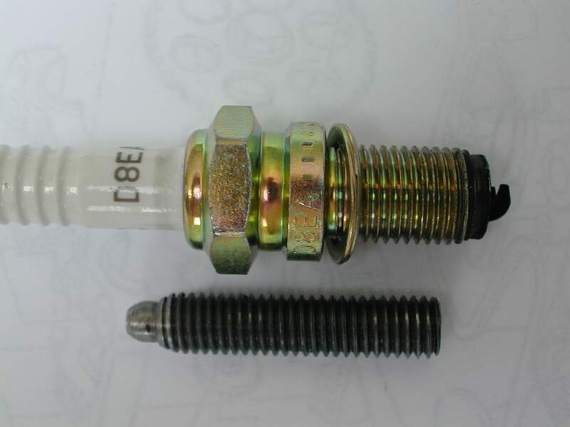
- A Top Dead Centre (TDC) Bolt.
Here is an
Original TDC Bolt. This is nice to have, but not ABSOLUTELY necessary as
discussed the TDC Bolt FAQ.
- TDC Crank Stop Bolt BMW Part # 90 88 6 116 570.
- A torch is useful to see the Timing Marks and to put in the TDC Bolt.
What is the Part No. of the TDC Bolt-Location Crush Washer?
It is an A8x13 copper washer available at a lot of good auto Shops.
Aluminium Works OK too. BMW Part No. 11 11 2 343 010.
Procedure
The bike MUST be cold, even after 4 hours
I got a 0.01mm difference when compared to leaving it overnight and checking it
again.
Taking it Apart
A. Remove GAS Tank
Why? To access the Valve Cover.
How? See
Gas Tank Removal-Replacement
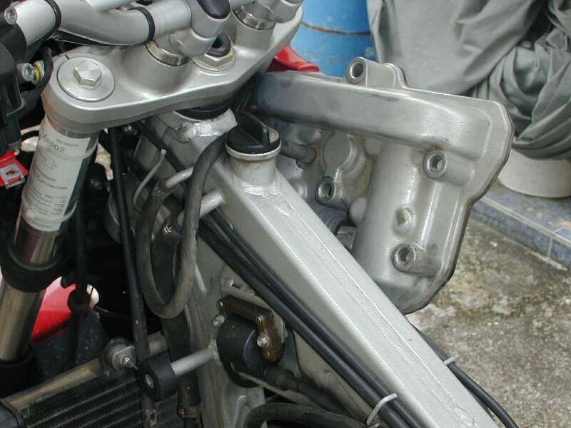
B. Remove the Valve Cover
- When the Tank is off you faced with this: The Valve
Cover. View from LHS.
View from RHS
- Gently pull off your Spark Plug Leads and remove a Spark Plug. This
will allow the Crank to be able to go a full cycle without fighting against
Cylinder Compression.
- Removing the Valve Cover entails undoing 6# M10 Bolts. You should
leave the Valve
Cover attached to the Breather Pipe, put a cloth around it and tie a piece
of string through a couple of the boltholes, hoist it up, removing it out from
the LHS Side of the Bike and over your handlebars and tie it firmly in place,
out of your way. Don't twist the Breather Pipe Hose (let it rotate at the Valve
cover if possible) if it's an older pipe and brittle, it may break.
The OEM clamp holding the cover vent to the vent hose is
non-reusable, so if you do take it off have a spare (small, about 10-12mm) hose
clamp handy to replace it.
You CAN get those OEM clamps back on, but it's not easy and not always
as tight as when you take them off. Bottom line is you don't need to remove it.
- The Cams and underneath them, the Shims, will be exposed.
C. Setting the Cam Gear Wheel Timing Marks Correctly
- Remove the plastic plug on the right side of the crank case with
a Coin or Screwdriver. Don't worry, no oil spills out!
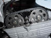
- Insert an Allen Key into the Hole where the Plug Was and turn the
crankshaft with a hexagonal socket (clockwise) until the
markings on
the camshaft sprockets are in one horizontal line. See this picture
Turning Crank to
get Piston at TDC.
OR
BMW put the Cam Timing Marks on the LH
Face of the Cam Gear Wheels, so you have to look at those from the LHS of the
bike, but turn the Crank from the RHS of the Bike, which can be a bit
uncomfortable. You then do not need to remove the Plastic Plug and turn
the crank with an Allen from the "Wrong Side" of the bike. You can simply put the bike in gear and
roll the rear tire until the lines on the cams are
parallel to the valve cover surface of the head.
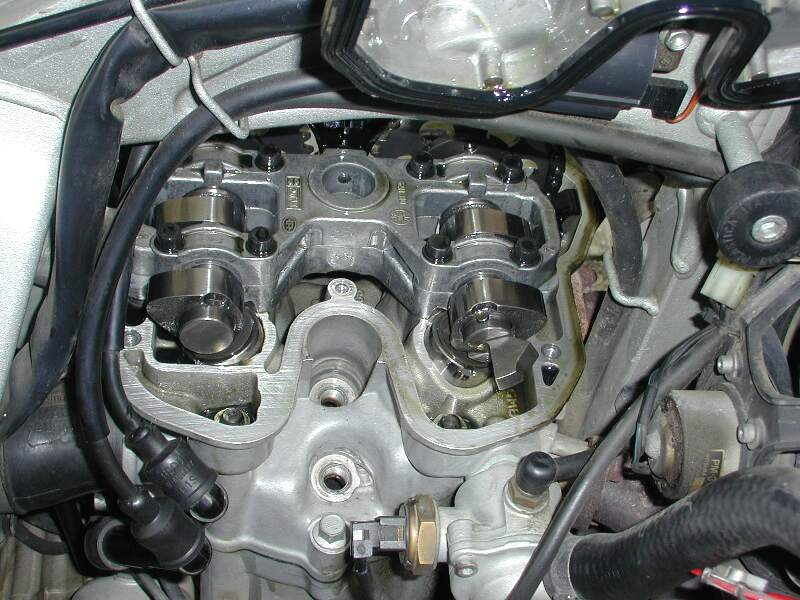
LOOK at the cams on the valves.
Either the "pointy" ends of the cams will be pushing the valves partially open
(overlap) or else the pointy ends will be up in the air and the round ends on
the valves (TDC on compression).
- Important! Note that it is possible to have TDC twice, 180 degrees apart, with the Cam lobes pointing
inwards or with the
Cam lobes pointing outwards, each being one of the 4 cycles of a 4-stroke
engine. For this operation, the Cam Lobes (the Pointy, rather than the
rounded ends) of the cams must be facing Outward.
The Exhaust Cams (Closest the Exhaust Header) must point (Pointy
end) to the front of the bike and the Intake Cams (Closest the Intake Rubbers,
Pointy end) must point to the rear of the bike. i.e. They should look like this:
Camshaft
Carrier Lobes Out.
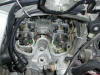
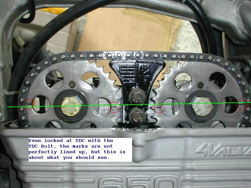
- For what the Marks on the
Timing Gear Wheels look
like after you've got TDC see here:
Timing Marks.
- Note that one person found his timing Marks would
NEVER line up, because the Factory had put one the Cam Chain on with one of the
Wheels off by ONE Tooth!
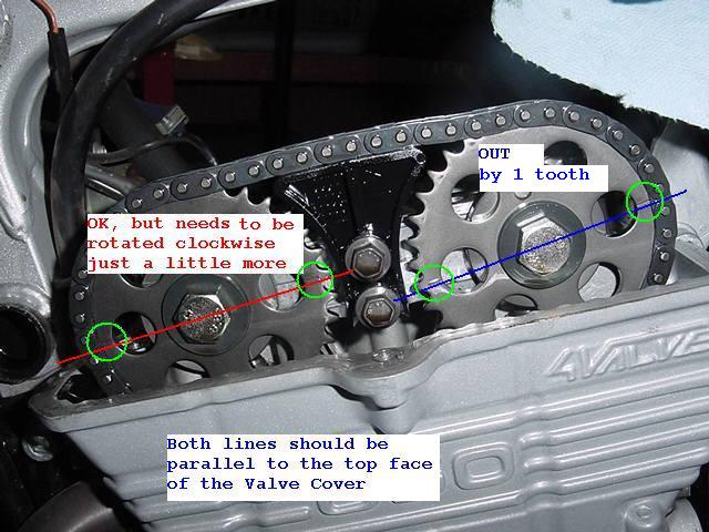
Here's a picture of what it should NOT look like:
Note! Marks don't line up?
Don't assume your Cams are out of time (off one
tooth) straight away. Try this first:
- I was reading over the FAQ about the valve
adjustment procedure on the GS and remembered that when I did my valve
adjustment the timing marks on the cam shafts did not quite line up the first
time I tried it. I turned the engine over about three or four more revolutions
(maybe more than that) and BING the marks aligned perfectly. Try this before
assuming that the cam is out of time. Paul.
- Those two lines on the cam gears which must be
parallel with the top surface of the cylinder head when you check the valve
clearances: sometimes they are not quite parallel with the TDC bolt in place. If
this happens, just turn the engine around and around until the lines are
parallel and the TDC bolt fits into the notch. This happened to me and that is
how I resolved it. Echo
D. Inserting the TDC Bolt
- After
you've got the Piston at TDC, you need to keep it there by locking the Crank
with the TDC Bolt.
- For a picture of the Bolt that holds the
Crank at TDC see here:
TDC Bolt
(Hint. It's not the Spark Plug ;-) )
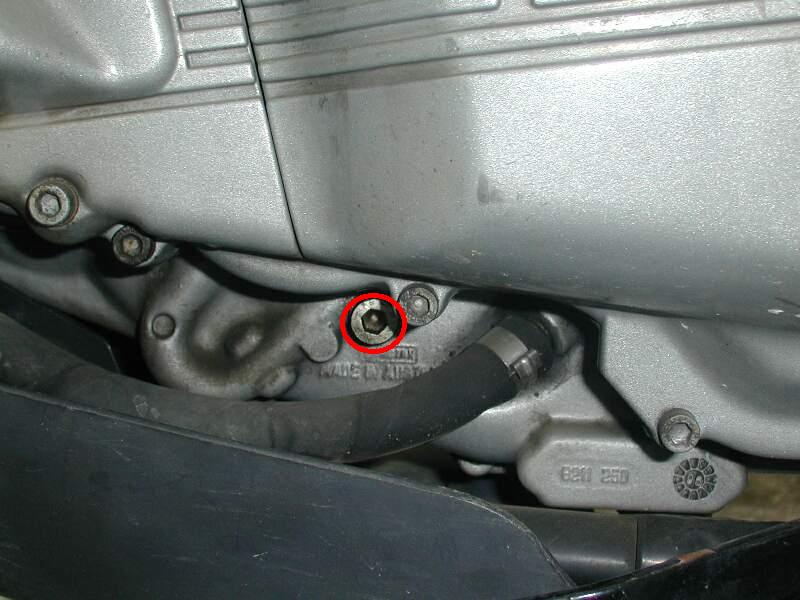
- For a picture of where the TDC Bolt goes see here:
TDC Bolt Insert Location
(You must take out that Shiny Silver Bolt First).
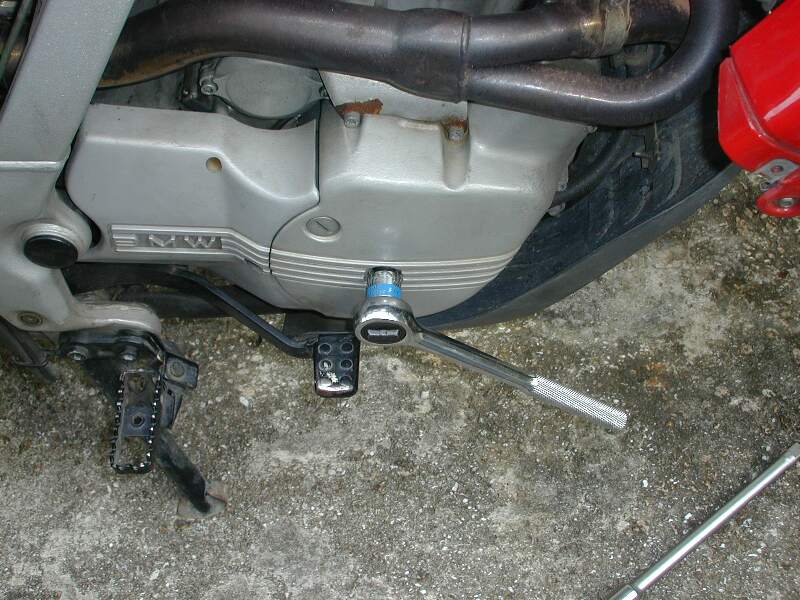
- For putting
in the Bolt at TDC, if you're going to take the Valve Cover off anyway, put the bolt in AFTER you get the cover off, so you can see which
way the Cam Lobes are pointing and you can see the Marks on the Cam Gear
Wheels. Put a ratchet (Or use the Rear Wheel) and a socket into the RHS Magneto
Cover (This is where you turn the Crank to get the Piston at TDC), because then
you can lie on the LHS of the bike, look into the hole where the TDC Bolt
should go and reach under the bike and turn the Crank until you see the hole,
then put the TDC bolt in. Use a flashlight. You can
also gently finger tighten the TDC locating bolt until you can actually feel it
lightly seat in the slot/mark on the flywheel.
- TDC on compression (i.e. Cam LOBES Pointing Outward
as noted above) is where you want to lock it. Remove the screw that occupies the
hole into which the TDC bolt goes and slowly screw the TDC bolt in. When you
feel it touch the crank, rock the rear wheel a few inches back and forth with
one hand while you slowly screw the bolt in with the other. There will be a
place where the "drag" will suddenly disappear and you can turn it a couple or
three more turns before it touches. THEN, you'll find that you can no longer
rock the wheel. You are THERE.
- If you're confident you have the Gear
Wheel Marks lined up at TDC, you can simply measure the Valve Clearances without
the Bolt. Just don't move the Rear Wheel. Put the Bike IN GEAR, this helps "lock
it" while you're measuring your clearances. The Downside of this is you MAY be a
slight bit off each time. With the Bolt you're always measuring the
Clearances at the same Crank Position.
E. Measuring the Clearances
- OK you've got it all apart,
set the Cam Gear Wheel Timing Marks Correctly and inserted the TDC Bolt. Now you
need to measure the clearances between the Cams (egg-shaped things) and the
Shims (Silver Disc UNDER the Cam Lobes).
- You can put feeler gauges in the Front TWO as they are
easy to access. Just slide (wiggle gently) the Feeler Gauge UNDER the Cam Lobe and on top of
that disc. These are marked GREEN in this Picture. The space is VERY SMALL.!
Use the gauge on the low side of the specification first and work your way up
until the gauge doesn't fit in. You
want to note what size gauge you can BARELY force in there without bending the
gauge.
- Try and check to the nearest 0.01mm.
You can double up two gauges to get finer
increments, just make sure they are clean. Even oil has a finite thickness. You can easily combine a number of the
feeler gauges (just add the numbers) if you don't have individual ones for every
0.01mm from 0.05~0.20 say. For a picture of the direction the Cam lobes should
be in at the time of measuring, see here:
Cam Lobes.
-
For the BACK TWO, you must insert the Feeler Gauge in the about 10mm x 3mm Slots
in the SIDES of the Aluminium Cam Carrier (Marked RED in the above picture) to
access the Cam Lobes.
- Note when checking the shims and
clearances, the numbers are never exact. This is definitely true when
using a feeler gauge. Even the Shims can be off a bit from the .05 mm
increments.
| Recording Shim Measurements |
|---|
Draw a Cross on a Piece of paper representing:
| Front of Bike |
|---|
| | Left | Right
|
|---|
| Exhaust
|
|
|
|---|
| Intake
|
|
|
|---|
| Rear of Bike |
|---|
Write DOWN your Clearances in each square
|
Note: I'm using the
TDC bolt (homemade: BMW's never heard of such a thing!) as well as looking into
the hole while rotating, looking for the middle of the detent, so I'm pretty
confident about lining cams up properly, but I note the point about sliding the
gauges in when readings mysteriously changed. Also, once there was a tiny grain
of sand (I live in a desert, go figger) on my micrometer, so all my spare shims
all went up by .05mm later in the day, leaving me rather disconcerted until I
noticed the sand. Have to be really careful about that in the future. Aleksander
in Dubai 98ST
F. Replacing the Valve Cover/Tank
- Check the Seal Surface of the Valve
cover is clean, Check the seal is in its groove, Replace the Valve Cover,
Torque the bolts to 10Nm.
- Replace the Tank. See
Gas Tank Removal-Replacement
- Don't Forget to Remove the TDC BOLT before Restarting your Bike.
- Don't Forget to Replace the Plastic Plug in the RHS Engine Cover.
That's it!
Many thanks to Flash, Richard, Todd, Marty436 & Johnathan Gifford,
for all their very constructive comments which are reflected in the FAQ.
