Steering Head Bearing Replacement FAQ
compiled & edited by Kristian #562
updates
edited by PDuffy#1244 & Kristian #562
Please read the Disclaimer before attempting any work in this FAQ.
General:
As often
reported on the Message Board, the F sometimes came with a
less-than-desirable amount of Grease from the Factory, resulting
in "Notchy" bearings after about 20-25K Miles, but
sometimes earlier.
Check FIRST
however that your tires aren't just worn.
Typical Q.
"My recently acquired '97 feels as though it is
falling into turns, especially left handers. I did note
the front Trail Wing is showing cupping and edge wear,
but is that the cause or the result? I can't see anything
else visually that would cause this effect."
-
That is typical of worn tires. Be sure to check the
tire air pressure. I recommend at least 34 pounds in the
front and 36 to 38 in the rear. Richard #230
-
I've been doing a bunch of maintenance to my '94
classic in preparation for a trip and I'm struggling to
decide if the steering head bearings are on the way out.
The bike has done 22000 k's and has a very small amount of
play in the bearings. The thing that's got me thinking
something's 'amiss' is a 'click' sound close to the end
of the lock each side when I turn the bars with weight on
the front wheel. The FAQ suggests a notchy feeling in the
middle, but mine is smooth in the middle. I did tighten
the handle bar rubber bushes. Cam
-
If you
do feel that there is a notch in the middle you could
just loosen the locking nut under the bolt a bit. This is
what the guy before me did, which made me not discover
that it was bad until many weeks after I bought it. They
say it is a common trick, before selling, to loosen it up
a bit, so that it is difficult to feel that the bearing
is bad. Spakur
-
Put the
bike on the center stand. Either have someone push down
on the luggage rack or else use a jack (and a board) to
jack up the front end just so the front wheel is off the
ground. (Note: jack too far and you'll raise it off the
centerstand and it'll go thump.) Squat in front of the
front wheel and grasp the ends of the axle, one in each
hand. Pull the axle toward you and push it away. If you
feel ANY play, your steering head is too loose. You want
to tightening your steering head with the wheel
similarly off the ground. You want to tighten it so that
with the wheel facing forward, knocking the handlebars in
either direction will cause the wheel to turn to its
stop, just barely. If it goes BUMP, that is too loose. If
it feels like maybe the cables are what is keeping it
from going all the way, it is juuuust right. Be aware
that when you tighten the top nut, it will generally
tighten the steering head up ever so slightly more. After
the steering head is properly tightened, THEN you can
feel for the notch, again with the wheel off the ground.
If you feel the notch, replace the bearings. Flash 412
(CO)
-
The clicking can be just a
cable flicking past an obstruction. Kristian#562
Tools:
- Allen Keys (in your toolkit,
or better still, a ½” or ¾” drive to
attach to your Torque wrench)
- An 8mm Spanner to remove the
front wheel Bolts. Socket or Ring Spanner. A
10mm Ring Spanner for the Tank.
- Either the low-headroom BMW
Socket (Which allows triple tree removal without having
to remove the handlebars) or a plain 30mm socket, which I
used.
- Drifts, Hammer, (Slide Hammer
useful but only for upper bearing).
- C-Spanner for the Upper
Bearing Circular Clamp i.e. “the Slotted Nut”.
A C-Spanner that does 48-52mm Slotted Nuts will do, or
you can use a Screwdriver at a Pinch, but there’s
less feeling.
- A propane Torch or Blow
Torch. Refer Tips in Wheel Bearing Removal Section
of the FAQ for using a Blowtorch for Bearing Removal.
What’s a C-Spanner ?
- A C-Spanner is a spanner to
do up the Slotted Nut and is shaped a bit like a sickle,
with a little tooth at what would be the sharp end of the
sickle. The tooth goes into one of the 4
"slots" on the slotted nut. Makes it easier to
do/undo the nut, BUT you can tap it gently with a
screwdriver or a punch. They come in various sizes and
one Spanner fits a range of Slotted Nut diameters,
mine’s 48-52mm. Very useful and cheap tool. Also
called a “Hook Wrench”, apparently.
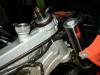
- Here is a picture of the C-Spanner/Hook Wrench on the Steering Head.
- It's also used for adjusting
preload on bikes that don't have the F's fancy preload
knob. (e.g. the suspension on a Cagiva Gran Canyon.)
- Thanks Josh & Jean.
- The flat hook wrench designed
to adjust the shock on a K75RT (BMW Part # 71 11 2 300
101, approx. US$6.00) can be used to adjust the steering
head collar (under the top triple clamp) on the Classic
F650. It is designed for a slightly smaller diameter
application, but will work as is. It works better after
filing the handle part of the curve to a slightly larger
diameter. It's also thin enough to avoid having to loosen
the handlebar mounting nuts to gain clearance. The
point on the hook end may also need to be filed down
rounder and narrower (depends on orientation of the flats
of the nuts underneath the upper triple clamp. Of course,
if you have the gas tank off anyway, this is not an
issue. Marty #436
Parts:
Bearings:
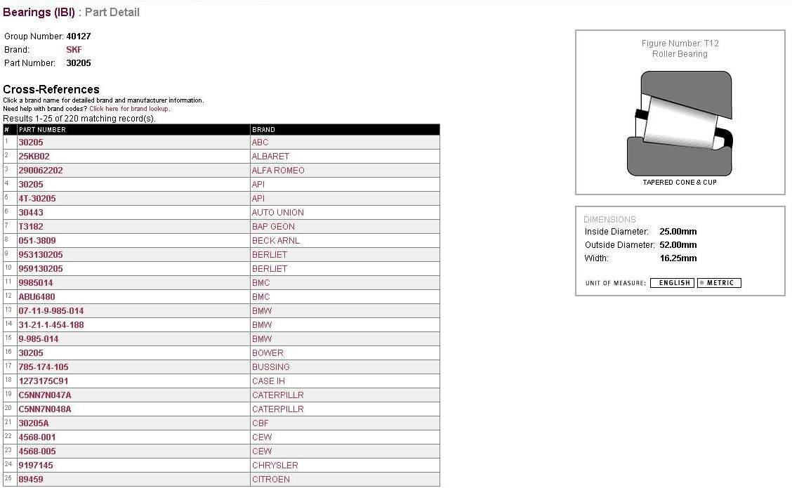
-
TWO
TIMKEN 30205M #90KM1 Bearings (The box for a
Timken 30205 will read as 30205 #92KA1 or 30205M #90KM1.
The "M" stands for through hardened steel as
opposed to case hardened steel that the 30205 #92KA1 is.
Both are valid part numbers with Timken however the 30205
is currently superseded by the 30205M. (Ref & many
thanks to Mark #403 for supplying email details from
Timken.). Jean #636 "got his parts from
A&W Bearings at www.awbearings.com part # NSK HR30205J made in Japan,
cost US$22.50."
-
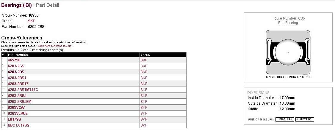
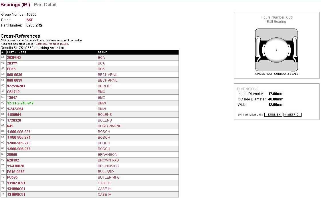
Or you can use another
good quality bearing company e.g. SKF
or whoever you know to be a good bearing manufacturer.
The Generic Number is 30205. Mine were SKF from a
Bearing Shop. -IMPORTANT:! Put the OUTER
RING (the part without the Bearings Attached) in the
Freezer.
-
Refer both Part
Number Bearing Schedule and
Detailed Bearing Information & Resources for further information.
Some HIGH Temperature Bearing
Grease.
-
Doesn’t need to be BMW but MUST be High
Temp. Also from the Bearing Shop.
-
The
steering bearing
problem is caused by a combination of low temperature grease AND
(in many cases) inferior quality bearings. The grease you
want is not just plain wheel bearing grease. Look for disk
brake wheel bearing grease. It's always rated
to a higher temperature. Any grease that is usable for
Volvo disk brakes will be suitable.
-
Types of grease used
by inmates:
-
BMW
#10 grease - Richard #230
-
SKF LGHQ
3/0.4 which is able to go to 175 centigrade with regular re-lubrication and
up to 150 centigrade otherwise. It says on the grease tube that over 120 C.
heat stabilised bearings must be used. Pat #1210
-
Grease stability is
different than the DROPPING POINT. In simple terms, the
dropping point is like a melting point...the temperature
at which the grease will flow by gravity. It could
"drop" out of the top bearing at a low
temperature, but still be a perfectly good lubricant to a
much higher temperature (it has to stay put to work). The
SKF grease is rated to 482F in dropping point, and also
has good water resistance (important ion the bike as
well). More tech data on SKF website. (Marty's (#436) comments on
LGHQ3/0.4: Excellent choice.
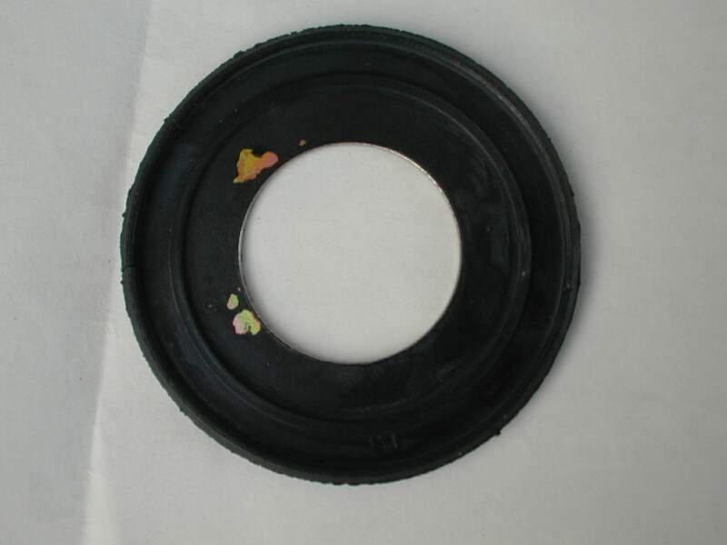
You MUST also get the Lower
"Rubber Washer" with the Metal Backing Plate
that sits underneath the bottom Bearing.
-
It’ll
either get cooked with the heat or you will damage it
getting off the bottom bearing. The washer is to
protect the bottom bearing, but is not intended to be
really tight seal. It's called a "Gasket Ring", only costs US$3 and is BMW
part # 31 42 2 345 287. NOTE:!! My bike and Jean
#636 had a Gasket Ring ONLY under the Bottom
Bearing. However Mark #403 notes: "There are
definitely two rubber/metal washers (Gasket Rings), one upper and one lower. the
drawings only show a lower one, but the parts list for
the drawing notes a qty of 2....and my bike definitely
had 2, plus the rubber cover. If I were you, I'd buy
another one and install it when you can. Shouldn't be too
difficult, since you only have to remove the upper triple
clamp to get at it. Even WITH an upper seal, I ended up
with water
sitting on the lower bearing, which is obviously why they
failed (rust). I wonder if originally they were only
using one, and changed to two later....".
The rubber boot/cover on top is part # 31 42 2 345 290.
(Again many thanks to Mark #403 for supplying parts
details). However the old one can be reused!
Tightening
Torques:
Note: Spakur's 1995 F Manual says 32Nm
on the 2#
Allen Bolts Front Brake Calliper to Fork Leg so Check the
year of your Bike.!
Feeling
Whether it’s really needed:
-
The Wheel Bearing Tip "Feeling for Worn Bearings" doesn’t work with the
steering head bearings because you can’t get your
finger in there to feel them. The Manual describes
grabbing the front forks at about the hub of the front
wheel and pulling them horizontally back and forward,
which might work if they are terribly loose, but I reckon
"notchy" is another feeling. The thing is
it’s NO GOOD just taking the weight off the front
wheel and testing your steering back and forth because
the load then goes only on the Upper Bearing and the
UPPER bearing doesn’t normally get that much load.
If you think about these bearings, because they are
tapered, it’s the bottom one that gets most of the
hammering. So you need to devise someway of being
able to turn the front forks WITH the weight on the
forks, i.e. over the bottom bearing. I did
this by putting the front wheel on a slippery surface and
with the weight over the front wheel, turning the
steering. DEFINITELY notched. So where do you
expect to feel the Notch.? Well unless you’re
driving around in CIRCLES all day my guess is that your
bike’s steering spends most of its time IN THE
MIDDLE and that’s where the Notch is.
-
Give the steering head
bearings the "Ouiji board" test. Bike on
centerstand, support the bike with front wheel off the
ground. Put ONLY four fingertips of each hand on each
handlebar grip. Slowly turn the bars from lock to lock,
paying particular attention when you pass through the
"straight ahead" zone. That's where you'll
likely find a "notch". Use your fingertips
(like Ouiji board) to feel any notchiness through the
grips. This is exactly how my bike felt before I replaced
the (BAD) steering head bearings last winter (haven't got
it out this year yet). BTW, check the Jesse bags for
tightness of mounting to the rack...they can be adjusted
to make them snug, if necessary. Marty #436
-
One
thing no one else has mentioned - if you squirt some wd40
into the head bearings and the wobble goes away or
changes then you probably have dried grease and need to
re-pack mike410(Iowa). (This only tells you about the
Grease, not the wear).
Sequence:
You will need
to remove in order, The Tank, The Front Wheel & Attached
Brake Line & Odometer Cable, the Handlebar (Unless you have
the BMW tool), the Triple Tree Fork Clamp Bolts, the 30mm Triple
Tree Nut, The Triple Tree, The Upper Bearing Slotted Nut (Using
C-Spanner), the Front Forks and FINALLY the Steering Head
Bearings (Outer Races (2# in Frame), Inner Race, 1 # on Shaft.
Sounds a lot but it goes fine if you work your way slowly through
it.!
Tank:
Removal
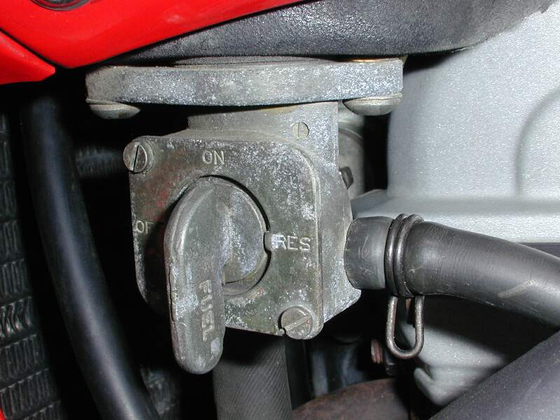
This will
allow MUCH better access to the steering head. To do this
you should first turn OFF the GAS petcock.
Also remove the SEAT. Preferably done with an almost empty
Gas Tank.
See the Gas Tank Removal-Replacement FAQ for photos and detailed procedure for the
Gas Tank Removal
Front Wheel
(& Attached Cables & Lines) Removal:
You need to do
this because otherwise you can’t get the forks LOW enough to
get the Steering Head Shaft out of the Frame. You could
conceivably drop it into a pit, but front wheel removal is so
quick and you really don’t want to be putting bearings onto
a shaft that has a wheel at the bottom.
- Place the Bike on the
Centrestand & Prop the Bike Under the Engine. You
might like to remove the Plastic.! “Bash
Plate” to do this. Prop it with something
stable, i.e. build up a Pile of Bricks. Alternatively
you CAN Tie Down the rear of the bike to a couple of tie
down points, because after you get the front wheel &
Fork off, the weight distribution is over the back wheel
anyway.
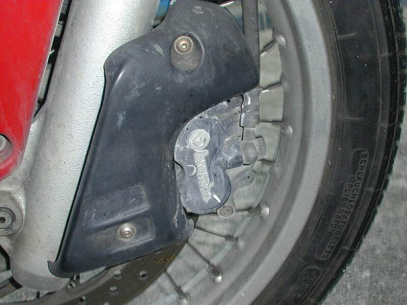
- Remove the Plastic Cover to the Front Brake (Small Allen key Bolts) and LOOSEN
but do not remove the large Allen Bolts that Hold the front Brake onto the
Lower Fork Leg.
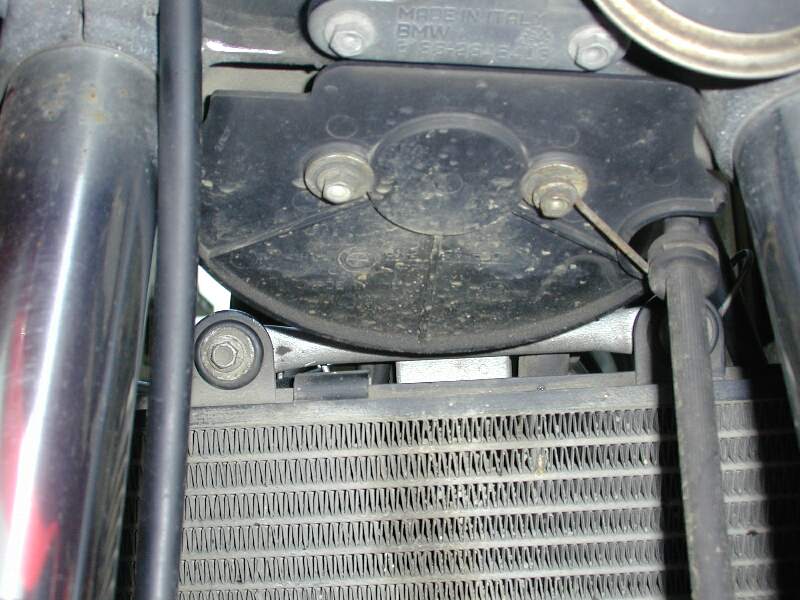
- Undo the connection of the
Brake Line and the Odometer Cable from the Semi-Circular Splash Plate (8mm Bolts) under the front
fairing. All the Parts attached the Forks should
now be free of the forks. Unclip the (Electrical)
Horn Spade Connector. You also need to get that
Circular Black Splash Plate off too.
- Remove the front wheel.
You do not need to completely remove the four SMALL 10mm
nuts, Front Axle Clamp Nuts just loosen them sufficiently to
get the Front Wheel Bolt (8mm Allen) Undone and pulled
out. That way you won’t lose the little
suckers. Ease the front wheel off, taking care the
disc gets past the Brake. Careful that you do NOT
Squeeze the FRONT Brake at any time during this repair as
the Brake Piston will Pop out when the disc is free.
You can Push it back in by hand but not too far.
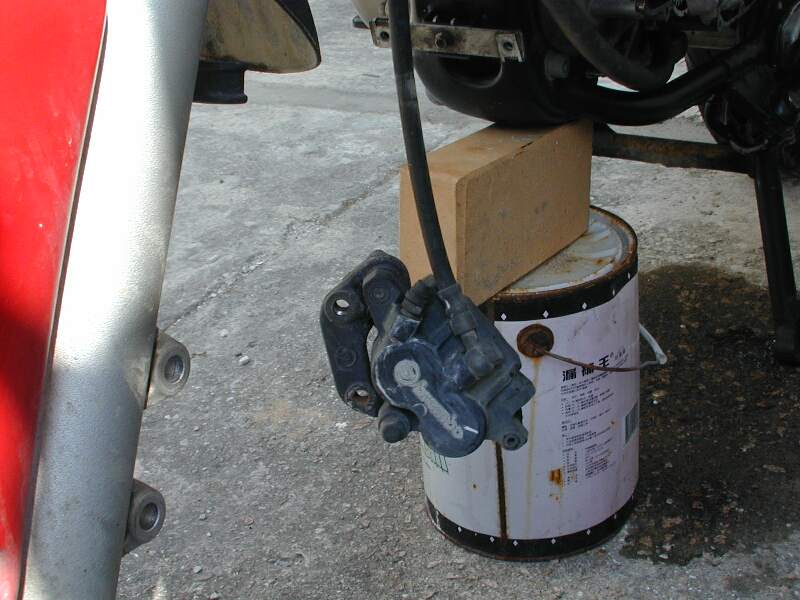
- Now remove the (8mm Allen)
Bolts holding the front brake
on. You might like to tie up the calliper a bit so it doesn't hang down and kink the brake line somewhere.
- Protect all the wiring/cables/plastic
with heavy aluminum foil (heat protection) before heating
the steering head area
Removing
the Handlebars:
- Prise off the plastic
Handlebar Mount covers and Mark the Position of the
handlebars with respect to the Mounts with a Pen. Use
an Allen Key to remove the Allen Key Bolts holding the
handlebar on. Remember that
the arrows, when putting it back, should be in the
driving direction, meaning straight ahead.
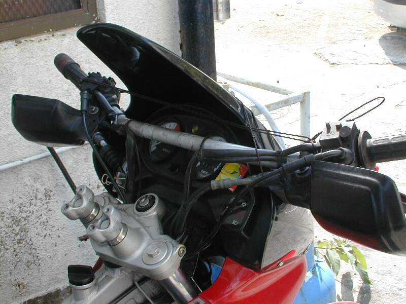
- You do not need to remove all
the cable & Lines to the Handlebars, simply Tie the whole lot back to your
Windscreen or
Dash, but put a Cloth over them first. Take CARE
you do not bend any of the lines or cables, i.e. use as
large a radius as possible. Don’t Grab the
Brake Lever.! To do this feed each line that is
both attached to the Handlebars AND enclosed inside the
two black holding bars beside the Ignition key, OUT of
this holding area. They will be much longer and
freer to work with.
If you have
the BMW 30mm Tool, I guess you can skip this as the Triple Tree Fork Bridge will come off with the Handlebar Mounts &
Handlebars attached, but frankly taking off the Handlebars is not
a Large Problem.
Removing
the Forks:
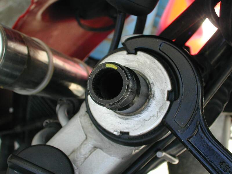
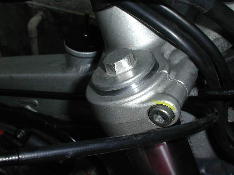
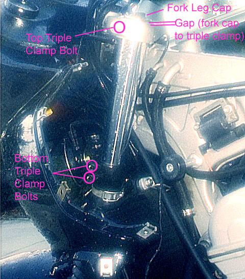
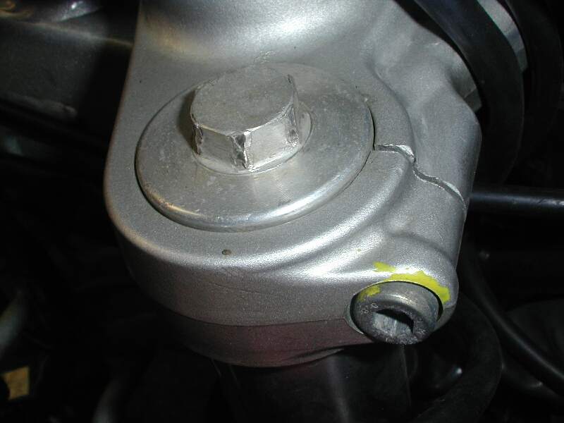
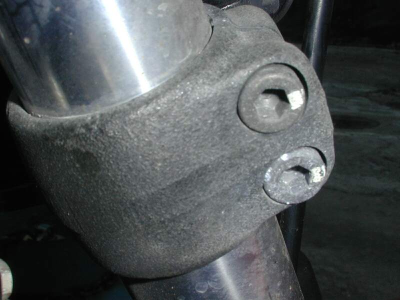
- Undo the 6mm Allen
Key Bolts CLAMPING the Triple Tree to the Forks i.e. Clamp nuts, marked yellow. (Do NOT remove the Large
Aluminium Caps off the Forks).
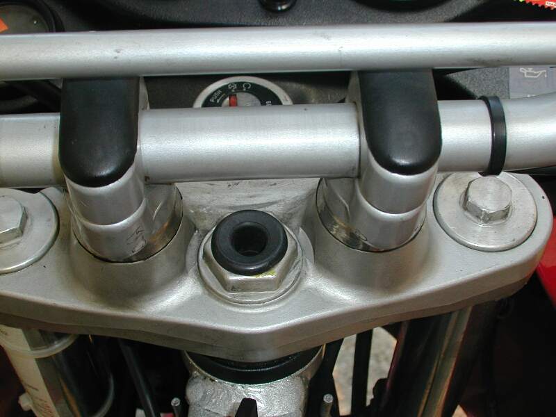
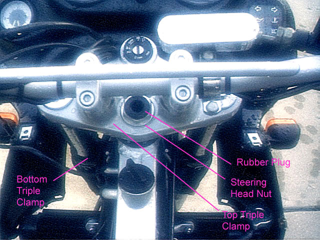
Marty #436 provided this
annotated Photo of the Triple Clamp Top and Sides. You do
not need to undo the LOWER Triple clamp bolts only the
upper ones.
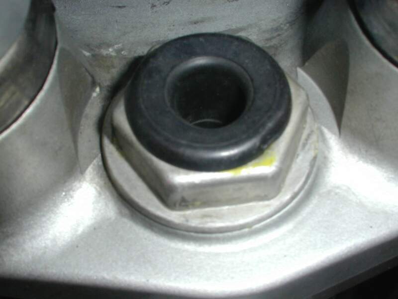
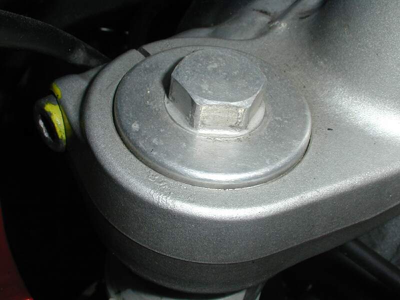
- Undo the 30mm Nut between the
Handlebar Mounts. Fork Bridge Clamp Nut. (Do not worry the Forks
won’t drop out until the Slotted Nut that you undo
with the C-Spanner is undone).
- Ease off the Triple Tree. If
it doesn't come off
- Undo the Slotted Nut with the C-Spanner and get someone
to HOLD the forks up until you’re done then get them
to gently ease the Forks Downwards until the Fork Shaft
is clear of the Frame. If after you’ve undone
the Slotted Nut the Forks Don’t drop out, use a
rubber hammer to Tap the Top of the Shaft. Normally
I would recommend putting the nut back on the shaft and
driving that but the thread is SO FINE and the NUT so
thin I do NOT recommend it.
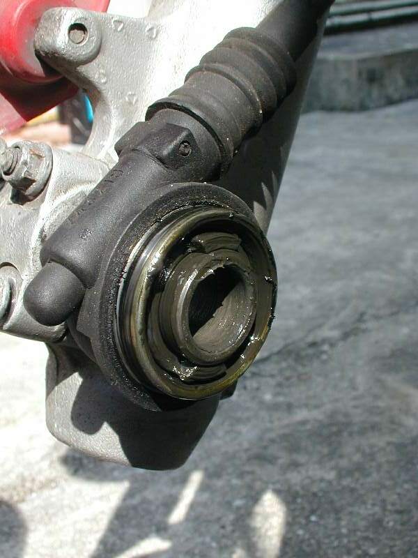
- Now you should have set of forks with a bearing (Inner Race Only) on the
lower part of the shaft. The inner race of the Upper Bearing should just be sitting in the
Outer race of the Upper Bearing. You can take this
out by hand.
- Make
sure you take a note of where your cables and lines are routed, you will need to put them all
back later and the correct routing is important.!
Bearing Removal:
Bearing
Removal is in two Parts: Outer Races (2#) and Inner Race 1# on
the Shaft. The Outer Races are like Steel Rings and are in
the Frame at the Top & Bottom the of Headstock.
Outer
Race Removal:
- To remove the outer races
grab your torch and Heat the FRAME around the Race (not
the race itself). Take care to NOT burn or scorch
the Cables/Brake Lines etc. i.e. put some
layers of Aluminium Foil Around them or sheet of
Aluminium. You CAN drive the Upper race COLD if you
have a BFH (BIG HAMMER) and a LONG Drift, but it’s
like pulling teeth. You need the Drift in any case.
Wear GLOVES, thick cotton Garden gloves or Leather ones.
- After applying the heat (Get
them good and hot), Grab you LONG Drift and drive the Top
Inner Race out from the Bottom, i.e. stick the Long
Drift in from underneath, through the bottom of the
Steering Headstock and drive the Upper race out of the
Top of the Frame. Work your way around the
circumference of the race until it pops out. Jean #636
notes: "The drift punch. I really fought hard
dislodging the old outer races before using a Drift Punch
with a 3/16" point. The one I used was made by DASCO
Pro reference number 603-0. I am sure there are other
tools you can use but this one made the job really easy.
(for the Lower Bearing) the drift has to be at least
8-1/2" inches in length to go all the way through
the frame tube."
- Removal of the Lower outer Race is the same as for the Upper, just heat the Lower Frame AROUND the Race
and drive it out using a drift placed in from the top, so
that you drive the race out the BOTTOM of the (Frame)
Headstock.
- A good alternative, for those of you
with access to a Welder, is to place a bead of weld
around the RIM or the INSIDE of the OLD bearing race.
When it cools, the bead of weld will try to contract and
cause the Bearing to also contract, allowing it to be
easily removed from the Headstock.
Inner
Race Removal:
The Upper inner race should already be out
by now, so this is only relevant to the lower one, which is a tight fit on the shaft.
- This one’s a bit more
tricky. If you bought a new Gasket Ring (the one under the Bearing) you
can both heat and whack that and not worry. Apply
heat to the bearing, but clean all the GREASE off it
first so it doesn’t smoke you to death and do it in
a WELL VENTILATED AREA. Heat it good and hot.
- Lie the Steering Head Shaft
and forks down on a Bench or on the floor, with the
threaded end of the shaft hard up against a Solid Piece
of Timber. The threads are very fine so don’t
drive against anything metal or concrete. You will
damage the threads. Using a drift (or slide hammer
if you can get the jaws on) drive the back of the bearing
toward the threaded end of the shaft. It’s
hard to do without damaging that washer and the Bearing
Race MUST Be HOT. Wear Gloves.!
- Alternatively, cut a piece of
thick foil to shield the lower grease shield. Then place
a length of thick walled tubing over the stem and run a
weld with a mig welder around the tube/bearing. Then used
a hammer and chisel on the weld to force it off.
- Don't forget to take off the
Rubber Gasket Ring if you damaged it.
Bearing
Replacement:
Inner
Race Replacement:
The Upper
Inner Race Just Fits over the shaft without any hammering, so
this is confined to the Lower Inner Race Only.
- Put
the Lower one on First. Don’t forget the Rubber
Gasket Ring with the Steel backing goes on
FIRST, Before the Bearing. The Rubber side faces
the bearing (i.e. up). If you damaged it and are 1
Million miles from a new one, use some Silicone to seal
the tear. If you can, use Lots of Ice in a water
bucket and place the Steering Shaft (With forks etc
attached) in the Bucket to cool the Shaft of the Forks as
much as possible before replacing the bearing. Alternatively
if you have access to some Liquid Nitrogen, spray some of
that on... :-). JOKE, but if you do use it,
careful it’ll take all the skin off your hand.
- Place the Bearing Inner Race
(It has the Rollers on it) over the shaft with the
Rollers facing UP i.e. Tapered so wide end is
closest the Bottom of the forks) and let is slide down
toward the Rubber Gasket Ring. It will get stuck
about an Inch or so above the Gasket Ring because the
shaft is slightly bigger at that point. Heat the
Bearing with your Torch, Good and Hot JUST the Bearing.
Alternatively you can heat the Bearing First and WEARING
your gloves, place it over the Cold Shaft and Drive it
Straight away. This way keeps the Shaft Cooler
longer but you MUST be careful of the VERY HOT Bearing.
The best way to drive it is to use a piece of thick
walled Pipe JUST larger than the shaft and drive that
down onto the bearing. A piece long enough to drive
from the top above the threads is most ideal. You
don't HAVE to heat it, but it can make the job easier. Don’t
Drive the needles or needle cage, drive the solid metal
next to the shaft. If you drive the needles or
needle cage you will RUIN the bearing. Don’t
drive using a screwdriver. Don’t use the OLD
bearing it will get STUCK on the shaft. Perhaps you
can file out or sand out the old bearing so it is big
enough to drive the old one without getting stuck, but
test it FIRST.! Jean #686 notes: "Putting
back the new lower bearing inner race I fought and swore
long and hard again before getting a 1"x18"
galvanized steel pipe with a rubber thingy on both ends
at the local hardware store. It's apparently a plumber
accessory. It rests nicely on the inside of the joint
without touching the needles and it's long enough that
you can hammer it without risk of hitting the top of the
steering column. It then went down like butter. I used a
heat gun but I am not absolutely convinced it was
necessary."
- Drive it all the way to the
bottom until it comes up nice and hard against the stop
above the Gasket Ring. You will both feel and hear
it when it reaches that point, it sorts of goes CLANG
rather than THUD. (You’ll know).!
- Do NOT drive the bearing with
the bottom of the SOFT Aluminium forks against something
hard, straddle the forks OVER something that comes up
against the MIDDLE of the LOWER fork brace.
Outer
Race Replacement:
OK, these are
relatively easy.
- Make sure the outer races
have been in the FREEZER for a while. Place in a
bucket of ICED water until you need them if your freezer
is at the other end of the House.
- Heat the Lower Frame at the
Headstock around the Outer Race Location, Good and Hot.
- Take the Race and drive it
into the LOWER Frame THICK END FIRST. i.e. Thin
end facing YOU. If you get it right (HOT &
COLD), it should slip in. I used the thick end of
the old race to drive it in but it got stuck and took a
bit of hammering to get it out. Use a piece of pipe
or something JUST smaller than the diameter of the thin
end of the race, but not a drift unless it’s very
BIG or it will damage the thin end of the race. Difficult,
because the end of the race you drive is thin. It
will also go clang when it’s in all the way and
seated against the flange.
Jean #686 notes: To drive in both the lower and upper
outer race I used a PVC pipe 1-1/2 in diameter and a foot long. I did not
want to use anything that was made of steel because I did not want to damage
the races. It took a lot of hammering but it went in (and the PVC pipe looks
now like it's been chewed on by a Doberman).
I used the torch but also a
can of air duster (I used this technique on the outer
races also - removing and installing) for cooling - it
was hard to get the lower race in because of the working
position. I also used some duct tape and taped the
old race to the new one, only on the inside of the race
so the tape didn’t get stuck in there so I could
focus on hitting it with the hammer. Spakur,
Sweden.
- The Upper Race is exactly the
same, ALSO Thin End facing YOU. i.e. Thick
end first. Drive from the Top.
I had the forks off anyway for Fork Seals, I put
the lower triple tree in the freezer overnight which worked very well. The
bearing was then heated up and slid down with relative ease. A short length of
suitably sized steel tube was used as a slide hammer to drive it home. Pat#1214
That’s your Bearings replaced!
Fork
Replacement:
- First GREASE LIBERALLY the
Lower Inner and Outer Bearing Races with Hi-Temp Bearing
Grease. (BMW#10 or similar.)
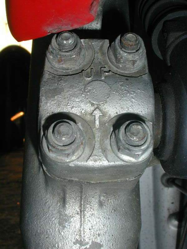
- Insert Steering Shaft (With
Forks Attached) in from the Bottom. Get Someone to
do this so you can Prop them with something under the
bottom of the forks, so they stay put while you work on
the top. Make sure the Cluster of four nuts that
lock the wheel shaft is on the RIGHT side and facing
forward. You cannot turn it later.!
- Grease the Upper Inner and
Outer Bearing Races with Hi-Temp Bearing Grease and pop
the Upper Inner Race (Needles i.e. thin end of the
Taper goes Down) over the end of the shaft and tap gently
onto the shaft. This bearing should go on fairly easily.
- Mine
only had a lower Gasket
Ring and so did Jean#636,
but Mark #403 notes his had two, a lower and
an upper. Perhaps rust protection.? At this stage the
next item to go on is this Upper Gasket Ring, followed
immediately by the Rubber Cover.
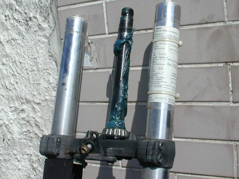
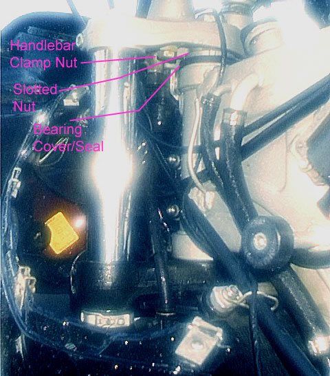
Marty
#436 provided this annotated
Photo of the Sequence.
- Screw on the Slotted Nut HAND TIGHT only at this stage.
This will stop the forks dropping out.
- You’re not going to
replace anything else at the moment, because we need to
get the wheel back on so that we can get some weight back
on the front of the bike, so that the correct adjustment
of the Slotted Nut can be made.
Wheel
and Cables & Lines Replacement.
- Fit the ODO connection back into the hub and ease the wheel
between the forks. Screw in the Wheel Axle Shaft.
The threads are on the left side. Torque the Shaft.
Don’t forget the Washer on the BRAKE side of the
Wheel. The Brake Disk goes on the left, odo on the right, both looking forward.
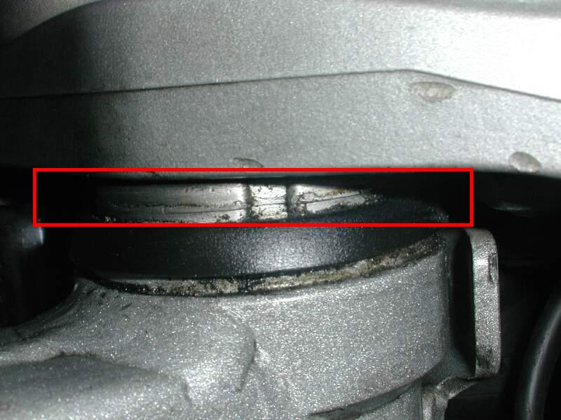
- Tighten the four 8mm nuts that clamp the Wheel Shaft. These are
safety nuts but they are very small. Torque the TOP
two first then the bottom ones. There will be a GAP
between the bottom shell and the fork frame after
tightening these. This is normal. Don’t
forget to Grease the ODO Connection and Shaft Before
replacing. Do not grease the part of the shaft
under the 4 Nut Clamp. Do NOT OVER TORQUE THESE
TINY NUTS.!
- Spread the Brake pads apart
with a screw driver so that they will fit over the Brake
disc. Only the Outer pad next to the Piston will
actually move so lever that one against the other one.
Place the Brake over Piston and Torque the two Allen
Bolts Holding it on. (You can also fit the Brake
and then the wheel into the Brakes, the way you do if you
have a flat tyre and you remove JUST the wheel.)
IMPORTANT: When you replace the Front Brake
Calliper, make sure the Bolt threads are clean and there
are absolutely NO bits of Aluminium or any other dirt or
swarf jammed in the threads. If there is, use a fine
screwdriver and a wire brush to clean them thoroughly. In
addition check there are no bits of Aluminium in the
threads of the Calliper itself. Test that it can be wound
all the way in BY HAND before tightening. If it jams
going in by hand, take it out and check it and clean it
again until you CAN screw it in BY HAND.
The reasons should be apparent, however any small amount
of Aluminium in the thread will start the bolt jamming.
If you tighten it further with a socket or spanner, it
can't screw in any more and starts ripping threads out.
Then with more Aluminium now jammed in the threads, as
you back it out it rips even more Aluminium out. You do not
want this to happen. Really Bad Karma. Do not exceed the
specified torque.
- Reattach the Plastic Fork Brake Cover.
- Reattach the Splash guard. Reattach the Cable & Brake line connections on the lower fork legs and
underneath the Splash Guard under the Front Fairing.
Re-attach the HORN Electrical Spade Connector.
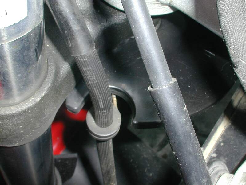
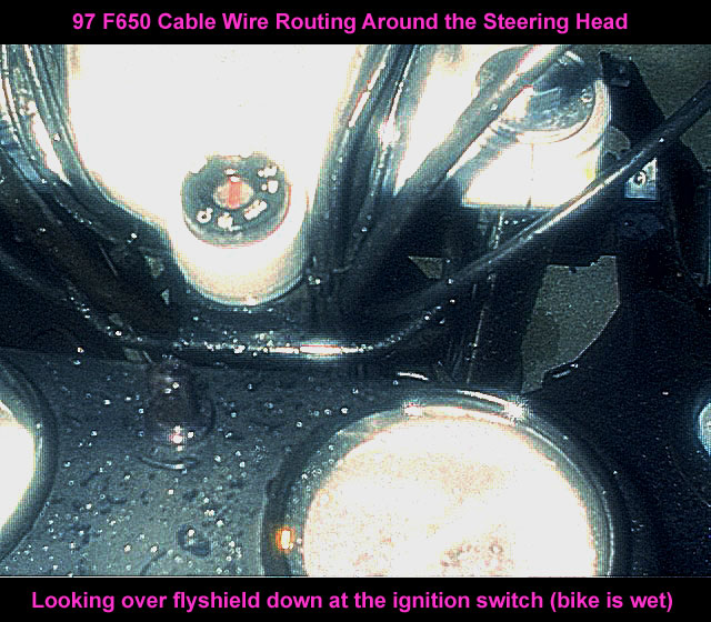
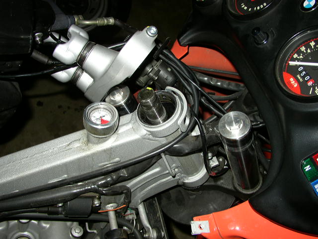
- Jean #636 notes: "It
was difficult to make sure that all the cables were
nicely back in place such as the odo cable in between the
fork legs, not outside the right one (when seated on the
bike), the brake line going under the ignition solenoid,
and the throttle cable that goes under the tank in
between the fork leg (not outside...) That may sounds
stupid but when you get it wrong you have to undo the
triple tree to (replace them right.". So true.!
So look first before you undo it. Marty
#436 provided this annotated Photo of the Cable Routing.
Triple
Tree & Handlebar Clamp Replacement:
- First you have to adjust the
play in the Steering Bearings. There should be
“No Play”, but this doesn’t mean cranking
up the Slotted Nut with an Almighty Force. The
Steering must be Free to turn without Jamming, but should
still have NO PLAY. So remove all the props under
the bike and allow the weight to go back on the front
wheel. Rock the steering back and forth a couple of
times to seat. Tighten the Slotted Nut with the
C-Spanner or a screwdriver in one of the Grooves, just
Until it’s Little Finger Strength Tight but NO
FORCE. Test it a few times to feel if it Jams or if
it is free. (You can also adjust the Slotted Nut
later on, it’s just a bit of a PITA to take off the
handlebars again.) Some folks may like to put the
Handlebars on first before tightening, to get the feel of
the Steering, I just found it easier to get to without
AND you need the BMW Socket to do this.
- Place the Triple Tree over
the Steering Shaft AND the Forks and Torque the 30mm Nut
down onto the Slotted Nut. Make sure the Triple
Tree IS over the Forks before tightening the Nut. The
30mm NUT MUST be tightened FIRST before the two fork leg clamps (marked with yellow splodge), or you will
stress the Triple Tree. Some folks use LOCTITE 248
(The removable one) on this Nut. Not a Bad idea,
but if you want to adjust it later you will need to
reapply it. NOTE: Strictly speaking, it
should be the LOWER Fork Clamps that you should undo, if you want
to maintain EXACTLY the 3mm Upstand between the Top of the Fork Plug
and the Triple Tree. But IMHO the movements are so small,
(But that doesn't mean the induced bending stress is
small) so I just undo the upper ones.
- Torque the two fork leg clamps (RHS). (Allen Key Bolts). Here's the other one (LHS). Also (marked with yellow splodge).
- Untie the Handlebars from the
Windshield and Replace on the Handlebar Mounts. Use your old marks for
height. Torque the Allen Keys down, rear ones first
then the front (This is an opinion). Replace the
plastic covers.
- Feed the Cables back into the
retainers. They should all be nice and loose on
Full Lock, both ways.
- Squeeze the Handbrake a few
times to get the Pressure back on the Front Brake System.
(To avoid giving yourself a Heart attack when you drive
off.)
Tank
Replacement:
See the Gas Tank Removal-Replacement FAQ for photos and details.
That’s IT.!
Go for a Ride
and Go WOW, Like New!..! Then Go Have a Beer or 3 and feel
very very satisfied with yourself.
Readjusting
Play:
If you
didn’t get it quite right you can readjust the play later
on. In this order:
- Remove the handlebars (or if
you have the BMW Socket just Loosen the triple Tree Nut
under the bars, this is where the BMW Tool IS Useful),
and Loosen Only the 30mm Nut with a Socket.
- Loosen the Fork Clamps (Allen
key Bolts) at the Top of Each Leg, NOTE: Strictly
speaking, it should be the LOWER Fork Clamps that you
should undo, if you want to maintain EXACTLY the 3mm Gap
between the Top of the Fork Plug and the Triple Tree. But
IMHO the movements are so small, (But that doesn't mean
the induced bending stress is small) so I just undo the
upper ones.
- Then adjust the Slotted Nut
with a C-Spanner or by tapping in the Groove with a
Screwdriver. SMALL INCREMENTS.
- Check Play. The
Steering must be Free to turn without Jamming, but should
still have NO PLAY.
- IMPORTANT. Torque the
30mm NUT up first BEFORE the 2 Leg Clamp Bolts or you
will put a bending stress into the triple tree.
- Torque the 2 Leg Clamp Allen
Key Bolts.
If steering head bearing play is:
"too loose" you'll feel vague handling at
high speed.
"too tight" you'll feel the bike feels
"drunk" and "staggers around" at slow speeds.
"barely too tight" you'll feel like it has
a steering damper on (Just right). Marty #436
Time:
I can’t
remember the total time exactly, because I did it over several
days, initially after work, under lights, munched by mosquitoes.
The first night I took off the tank and the forks. With ALL
the Tools at Hand:
- Tank off - 10-15 mins 10
Allen Screws, 1 10mm Bolt. 2 Line Disconnects.
(I've got that down pat, doing the rejetting/needle
change a few times!) reckon about ¼-1/2 hr for Tank
virgins.
- Drop Forks out - ¾ hr-1hr,
lets see that’s: 4 Axle Retaining Nuts, 1 Axle bolt,
2 Brake Allen Cover Screws, 2 Brake Allen Bolts, 2?
Splash Plate Bolts & Odo/Brake Bolts, 4 Handlebar
Mount Allen Bolts, 2 Fork Clamp Allen Bolts, One 30mm
Nut, One Slotted Nut.
- Remove Bearings - Hmm Say 1
hr i.e. Top Inner Race 30secs Top & Bottom
Outer Races - ¼ hr-1/2hr Bottom Inner Race ½ hr.
- Put On New Bearings: 1 ¼ hr
Max.
- Top & Bottom Outer Races
- ½-3/4 hr Bottom Inner Race ¼ hr-1/2 hr Grease,
Reassemble Forks & Wheel & Torque & Adjust
Say 1+1/2 - 2 hrs. Methodical.
- Reassemble Tank ¼ hr-1/2 hr
Max Go for a Test Ride 3 hrs :-)
- Congratulatory Beers on Sofa
3 hrs :-)
- Total Without Test Ride &
Beer 5 ¾ to 6 ¼ hrs, Working Methodically.
"After 4
hours I had put the new bearings in place, but it took
another 4 hours to get everything back on". Spakur
Sweden. YMMV.!!
Cost:
- Bearings: About
US$5 Each.
- Grease:
About US$5 For more than you’ll need in a Lifetime.
- Blowtorch: About US$20
for Torch, 4$ for Gaz.
- Beer:
About US$20 Now that’s a lot of Beer.
This assumes you have or can borrow (At
least the Torque Wrench) all the Tools, including Allen Keys,
Sockets, Ring Spanners, Torque Wrench, C-Spanner, Drift. Thanks
to Mark #403 who was the first to use the FAQ and Jean #636 who
was the second, both of whom came back with some great comments,
as well as parts numbers.
Steering Head
Check and Bearing Relube (NOT Replacement)
by Langlois
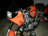
The F650s are known for being underlubed so I am
adding this to the 6K service, here are the photos.
|
Pop off
handlebars, hang to the left side with the upper triple clamp. Move tank
back on frame or remove.
 |
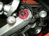
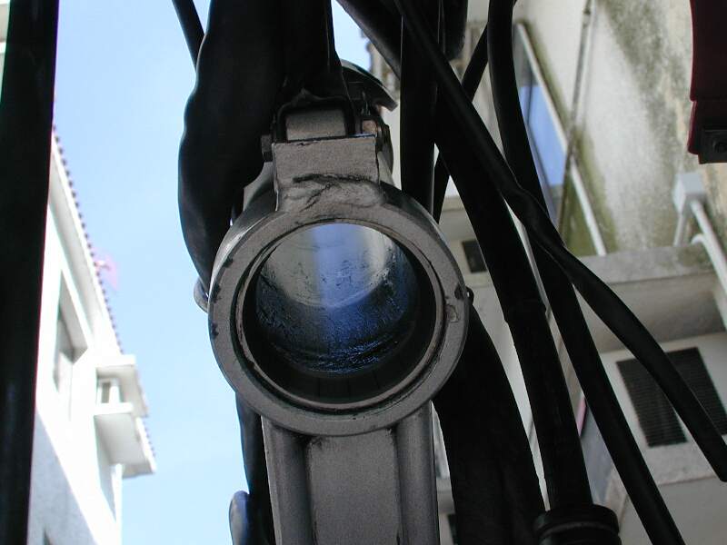
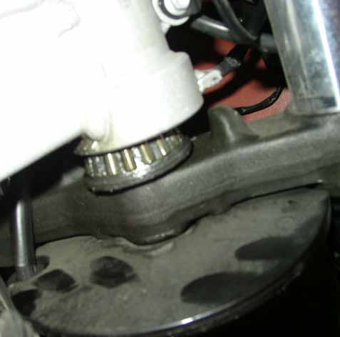
Upper
bearing race, not bad, needs grease.
 |
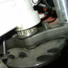
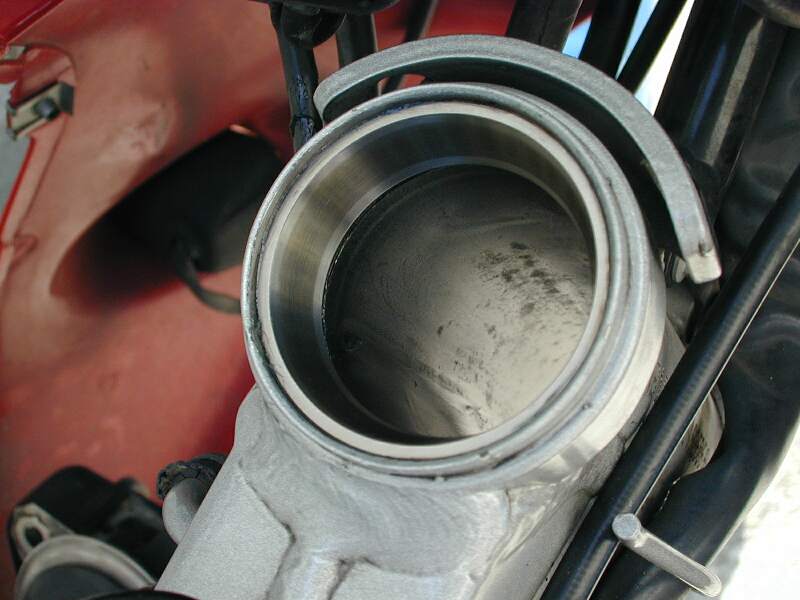
Lower
bearing, has lube, does not look bad, just needs some grease.
 |
|
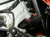
Lower
bearing re-greased. (after wiping the race and bearing of the nasty old
lube, not that there was much!)
 |
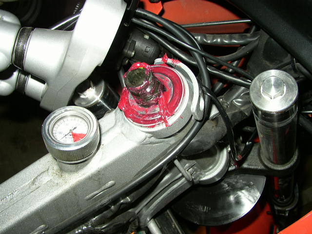
Upper
bearing, greased. This grease is either Mobil 1 or the Castrol equivalent, I
keep a grease gun full of each handy. I have had very good luck with the
Mobil 1 grease with other high wear applications and really like the stuff.
I also use the Castrol and like it as well.
 |
All buttoned
up and ready to assemble. Note anti-seize liberally slathered on threads, I
love the stuff, you should too. I find the F650 notoriously "dry" when it
comes to thread lube.
 |
Total time, messing around, dawdling, taking my time
added an hour to the service.
Flash #412, Hombre
Sin Nombre, Mark #403, Haakon #636
Steering
Head Bearings
The box for a Timken
30205 will read as 30205 #92KA1or 30205M #90KM1. The
"M" stands for through hardened steel as opposed to
case hardened steel that the 30205 #92KA1 is. Both are valid part
numbers with Timken however the 30205 is currently superseded by
the 30205M.
At 13K miles my OEM
steering head bearings gave out on my '99. Upon disassembly they
were the expected Bulgarian models. I couldn't find suitable
substitutes locally, and had a friend in California looking for a
specific model of Timken. Unable to find what I wanted, or a good
substitute, he went to the BMW dealer to buy my new seal rings.
He checked on what they had available, knowing that I did not
want to use the OEM Bulgarian models. I was pleased to find that
the new replacement bearings in the dealers stock, in BMW boxes
with BMW part numbers, are SKF's made in Germany (SKF 30205 J2/Q)
and cost less than $10 each. Hopefully these should be much
better than the original bearings, at a very reasonable cost. So
if you need to replace your Bulgarian bearings, don't be afraid
to see what your dealer has available before you go to additional
trouble to search out an alternative source for something other
than the original Bulgarian bearings.
I wonder if we could find
a slightly thinner bearing or with a different tapered race? The
Timken catalogs won't let me search by dimensions. The
reason I mention this is because originally on my bike, I
discovered that the upper seal ring did not fit down into the
recess for the race, not providing a full seal. Lifting the
flexible rubber cover, I could see the bearing rollers. I think
the original race was fully seated, but the Bulgarian bearing in
its race was almost 1mm thicker overall than the new SKF
bearing. The new race is fully seated (I inspected it with a
mirror), and the seal ring almost, but not completely, seats
inside the race recess. Much better seal, but I wish the seal
ring seated entirely within the race recess, as it would with a
slightly thinner bearing. I also note that the upper lip of the
race recess is NOT in true alignment with the bottom of the race
recess, the welded ring/lip that the race bottoms against, almost
1.5mm of difference - very poor QC on the part of whoever made
the frames - it would matter less if I could get the ring to seat
deeper inside the lip. And I WISH there were room for zerks,
however there just isn’t the space.
Steel alloys' molecular
structure will arrange itself differently depending on how it is
heated and cooled. Take a materials science course to learn all
about metal phases. "Through hardened" means that the
entire part has the same hardness throughout. If you took a cross
section of the item and tested the hardness in the center, it
would be identical to that of the outside surface. "Case
hardened" means that, sort of like a Twinkie, the soft
center is surrounded by a harder exterior covering.
The difference between
through hardened and case hardened can be considered analogous to
the difference between solid gold and gold plated.
A through hardened steel
race has a (more or less) uniformed hardness through the entire
cross section of the race - basically, it's the same hard metal
inside and outside. Because this is actually a cheaper priced
bearing, I'm guessing it's a special proprietary alloy. (Bearing
mfg's are SERIOUSLY into special alloys and metal treatments.)
The race may be very hard and strong, but will be more brittle,
possibly subject to certain types of cracking, before it warps.
Tensile and ductile strength may be higher, while yield strength
may actually be lower. (Harder usually means more brittle.) A
case hardened steel race is usually also homogeneous metal
throughout, but it has been hardened after manufacturing. Usually
this is surface hardening, the depth varying depending upon
intended application. Think of it as similar to
"tempering" the surface of the metal. While the basic
alloy of the metal is the same throughout, the molecules on the
surface may be re-arranged, either mechanically, or thru ion
exchange, or have additional elements, such as other metals, or
in the example of case hardening, usually carbon. This is usually
accomplished by additional treatment processes after basic
manufacturing. The surface (sometimes to a considerable depth)
can be made MUCH harder than the original alloy. Since it's all
one single piece of metal, and the original underlying alloy can
be more ductile, the overall effect can be a race that is less
brittle, and less damaged by warpage, and possibly even harder
than the through hardened type M bearing. I don’t know which
bearing surface is actually harder in this case, probably
proprietary Timken info.
Detailed Bearing Information &
Resources
by Haakon
#626.
For other alternative
Bearing Parts Numbers refer the Bearing
Schedule.
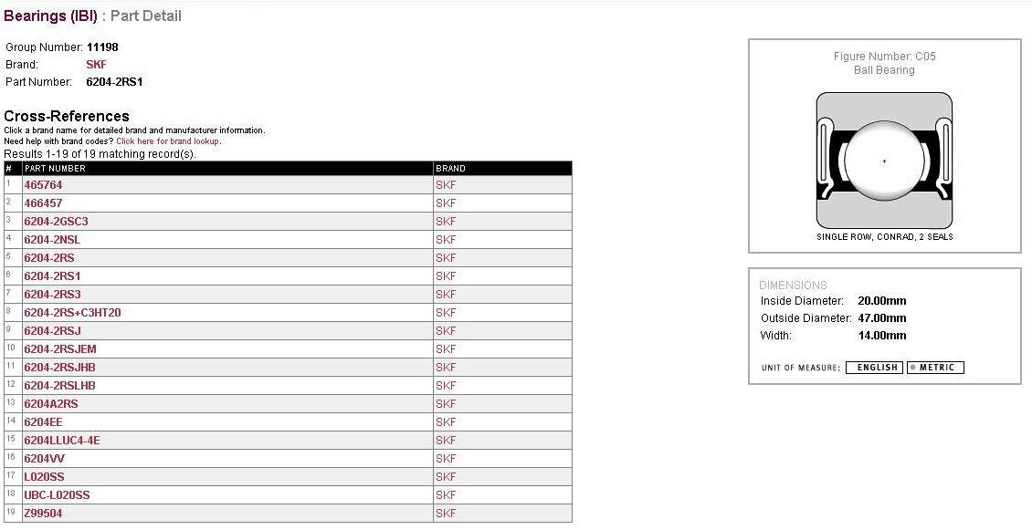
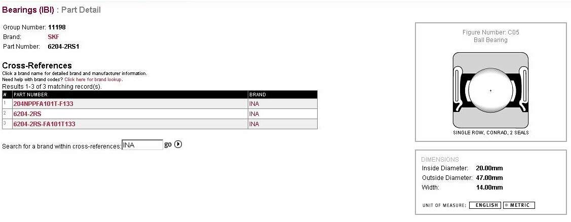
In the Wheel Bearing Replacement FAQ the section with the GS/Dakar
Sprocket Carrier the bearing is 6204-2RS1/ C3. The
"/C3" designation is rather important as the bearing is
a "shrink" fit in the carrier. The C3 tell us the
bearing has a bigger internal bearing clearance than normal. That
is used so that when the carrier cools down it clamps onto the
bearing a bit and thus eliminates any "looseness". If
you fit a standard clearance bearing in the carrier it will be a
bit "tight" internally. http://www.timken.com/products/bearings/techtips.asp.
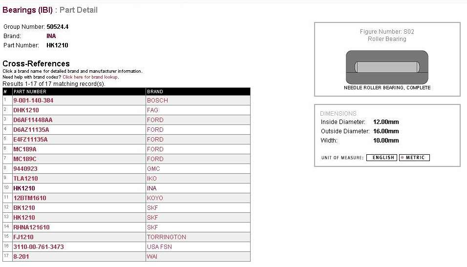
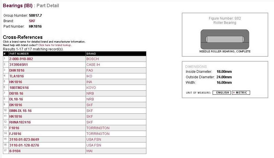
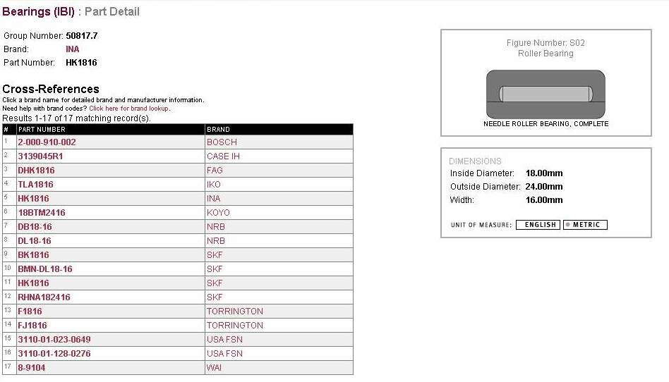
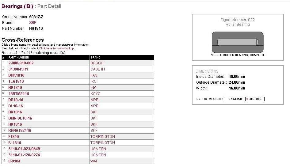
You can have the same
nominal size e.g. 18x24x16 needle bearing in different formats,
for instance,
- Loose: a group of individual loose
needles, no carrier or shell, just loose needles.
- Caged: needles held in a plastic or
metal cage, usually with inner and outer bearing surfaces
exposed (plastic cages might not have been as popular in
your 1984 index) and
- Shell: needles held inside a tube
(usually metal) with narrowed or crimped ends that retain
the bearings. Usually there are 1-2 less needles for the
same size bearing, because of the shell. Similar to a
"cage" but only the inner bearing surface is
exposed, the outer bearing surface is contained inside
the shell, which is inserted as an assembly when
installed.
Now:
- If the bearings were loose needles
(not used much today due to cost- then you have to use
hardened and ground surfaces on both the "axel"
and inside whatever "housing" you have) only
the diameter and length is used.
- Same as (1) expensive to use, size
given as Inside Diameter-ID/ Outside Diameter-OD and
Width-W.
- This is what I BELIEVE is used by BMW.
An outer shell and the needles held in place with a cage
(to be honest it was also the only type I found with the
right sizes) The use of a cage inside the shell is to
prevent the needles to accumulate where there is the
least pressure, and "opening" a gap where the
pressure is. That does not matter a lot when the bearing
turning. In the linkage and rear- swingarm we have a more
or less static load and then it is not good. Of course,
without a cage you get to use more needles = more bearing
surface.
Some Alternative Bearing
#'s.
Classic Feedback
Please note there is very
little Feedback on this item because this was one of the first FAQs and at that
time "Feedback" was not taken. It doesn't mean it didn't happen and that there
wasn't a problem on the Classic. It does happen and it IS a problem. You can see
from the FAQ above at least 10 people did by themselves. If you have done it or
had it done, please email
The FAQ so we can record it here.
Thanks, ed
See the
Survey Section
for early feedback.
-
My shop did the
job under warranty. Apparently the type of grease used at the factory could
not take the heat of the oil-in-the-frame concept, and headed for cooler
climes, leaving the bearings without grease. As I recall, they charged BMW
for 5 hours of labor and about $20 for parts (really cheap bearings).
Richard #230: 1997 Funduro
Differences for the GS
So far there have been very few reported
cases of the SHB notchiness on the GS. The procedure is very similar to the
Classic, once you get the Panels off the bike. If you have the answers to any of
these questions, please contact The FAQ
-
Has anyone out there done the SHB on the
GS/Dakar? Any significant changes from the FAQ apart from the plastic-related
stuff?
-
What's the fall-apart curve on the SHBs?
In other words, will they rapidly degrade from here on in, or will they last
10,000 miles before they get really bad? Are we talking safety hazard here, or
-
Has anyone paid a shop to do this? If
so, how much did they get screwed for the work?
GS Feedback
-
When I had the front wheel of my '01 Dakar (33,600 miles) in the air to get a
good look at the big honkin' ding in my rim, I noticed that there was a barely
perceptible but definitely there detent in the SHB. As expected, it's right
where the front wheel is pointed straight ahead. Or rather, you feel the "bump"
as you turn the bars away from being pointed straight ahead. This, as I
understand, is an omen that the SHB are due for replacement. Naturally, I
checked the FAQ first to see what was involved. Holy crap, this seems to be one
mother-strapper of a job. Propane, freezing, BFH's, specialized tools. As a
follow-up, I called up my shop to see what the flat-rate was on the bearings,
and they quoted me 3.0 hours. No warranty coverage, according to them. Robin
#790, '01 GSD Chicago
-
Only for statistics: On my F650GS 05/00
23000 km (15000 miles) the head bearing is broken. Robert #1071
-
My bearings were noticeably notchy for about 10k miles before I replaced them
(when on the center stand the front wheel would click into the straight ahead
position) - and there was no great catastrophic failure or anything. That said I
sure did notice the difference after they were changed - it got so much easier
to turn corners, brake hard, manoeuvre the bike etc. On the other hand it was
harder to ride slowly in a straight line after the new ones were fitted. I would
recommend changing them very soon as there is an obvious safety concern here and
although I decided to risk it was probably a dim move. That said I was 3
countries away from the nearest BMW dealer at the time so I had more logistical
challenges in the way. y_kiwi. Lance, #1303, '01 F650GS.
Are SHB Warranty Work?
by Marty #436-Chicago-97 F650F
My SHBs are notched at 29K miles. I'll probably replace them myself, but as long
as I was at "Chicago BMW" this morning I asked them if it would be covered under
warranty. They said "No, it's a normal wear item.". Have people here had any
luck replacing SHBs under warranty? Raymo #1173, Chicago, 2001 F650GSA
Look at the warranty page in your owners booklet. It will tell you that
BEARINGS are considered normal wear items. My wheel bearing was toast at
13K...sorry, no warranty. My SHBs were toast at 25K (out of warranty), so sounds
like you did OK on mileage. Be sure to use QUALITY BEARINGS from a bearing house
and a QUALITY, WATER-WASHOUT RESISTANT GREASE that is rated for HIGH-TEMPERATURE
(Classics only) and, preferably, good against fretting wear as well. (Unlike
BMWs OEM stuff). You should do much better on mileage with the quality stuff.

