GS Steering Head Bearing Replacement FAQ
GS Steering Head Bearing Replacement FAQ
Compiled and written by Scott, ID #1244
Special thanks to NothingClever and Oyvind for their input.
Please read the Disclaimer before
attempting any work in this FAQ.
Last Updated: 23 September 2006, by Winter #1935
For other related FAQs:
Suggested BMW parts and part numbers and tools for the GS
| Suggested BMW parts and part numbers |
|---|
- Steering head bearings (two) 31 42 1 240 571 (320/28X 28x52x16) Note: This number may have been changed to 07 11 9 985 070
- Spacer (protective cap, two) 31 42 1 234 509
- High temperature bearing grease
Note 1: Most auto parts stores sell the appropriate bearings (ask for
two BR32 bearings). If you are careful, you can re-use the "spacer"
(metal cap that covers the bearings). However, driving the bearings out
with a machinist punch may perforate these caps. Lastly, bearing
replacement can be done without the special BMW socket, though the socket
no doubt makes it easier. Scott ID, #1244
Note 2: See the Parts and Fiches
FAQ for alternative part numbers
|
| Suggested Tools |
|---|
- Torx drivers
- Torque wrench
- Allen wrenches, including a 12mm allen wrench for counter tube
removal (see step 5-B below for substitute)
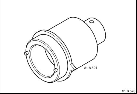
- Socket: BMW Specialty Tool 90886316521; shown as 31 6 521 in BMW
shop manual(Diagram of
BMW Tool)
- 3-4 mm machinist punch to drive out bearings and races (longer the
better)
- 30 mm socket for SHB hex nut
- 10 mm wrench for ABS sensor
- Hammer
- Long punch or regular screw driver for driving outer races
|
Replacing the Steering Head Bearings
Below are some instructions regarding the replacement of the GS
steering head bearings. These are collections of experiences from GS
riders who have replaced their steering head bearings. See also the
Classic SHB
FAQ for more insights, and for testing to see if your SHB's even need
to be replaced. Replacement of the Steering Head Bearings will require a
few preliminary steps, including the following:
Remove Handlebars
- Remove cross bar pad (Dakar)
- Remove 4 screws holding the plastic panel housing the ABS
and heated grip switches (if installed), and lift housing from handlebars.
Set aside and let hang to the right side of the cockpit.
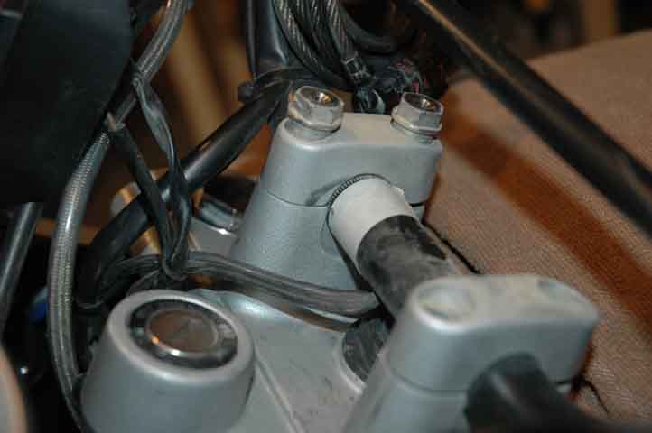
- Remove the 4 bar clamp bolts from the handlebar clamp.
Note that the top clamping blocks are not symmetrical, so look to see what
orientation goes forward (the BMW manual says, "wide hole spacing to the
front"). Also, place a piece of masking tape on the handlebar next to a
clamp. Make an index mark on the bar to note your handlebar position
(Photo)
- The handlebar will be a bit sticky to remove. Using a
rubber mallet (or steel hammer and a block of wood), tap the handlebar
from below, driving it upward to loosen it from the bottom half of the
clamp.
- Bungie the handlebar to the windscreen (to keep it out of
your way). No need to remove handlebar cables, etc.
Remove Front Wheel
- Jack up front of bike so that the front wheel is off the ground.
This can be done with a floor jack, or place the bike on the centerstand.
If you use a floor jack, you might want to remove the engine guard, or at
least place a short length of wood between the jack and the engine guard.
Once raised, the bike might be wobbly. Be sure to secure the bike such
that it doesn't tip over.
- Loosen the axle clamp bolt. Loosen the axle bolt, and slide it
out. Watch for the spacer on the threaded end of the axle. Carefully roll
out the wheel, easing the brake disk out from the calipers. Be sure to
not damage the ABS sensor if you have it.
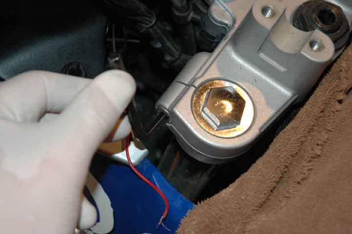
- Remove the brake caliper and ABS sensor if you have it.
See Front Wheel Removal
FAQ for more information.
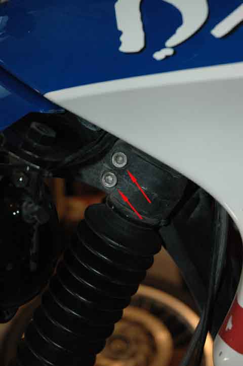
Fender and Horn Removal
Using a torx driver, remove the 4 bolts from the bottom side of the
fender (Photo).
There are 4 washers on the backside that you can't see until they fall
out upon fender removal (note: fix these washers back onto the backside
of the fender with a little smear of silicon RTV. This will make it
easier for you when you re-install the fender bolts later on). Once the
fender is removed, using a larger torx driver, remove the single bolt
holding the horn in place
(Photo). Disconnect the wire harness from the horn.
Fork Removal
- Note the depth setting of the top end of the tube. Is it flush
with the top bridge? A bit lower? You will want to know this when you
install them later on. OK, loosen the top
(Photo) and
bottom (Photo)
fork clamp bolts (one each side on top, two down low), and slide out the
fork legs. No need to remove the fork stiffener brace, nor the end cap
on the top end of the forks. Set aside in a safe place. If you nick,
dent or otherwise damage the tubes you may facilitate fork seal damage!
- See also Fork Maintenance FAQ
for more info.
Steering Head Bearing Removal
You can use heat and ice (see "Feedback" below) if you wish, though it
seems these bearings and races can be removed without. The following
description does NOT use heat or ice.
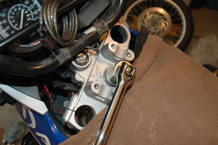
- Using a 30 mm socket, remove the hex-shaped collar (retaining) nut
(Photo)
- Using a 12mm allen wrench, or
the handle
of a large machinist punch and a wrench, remove the counter bolt.
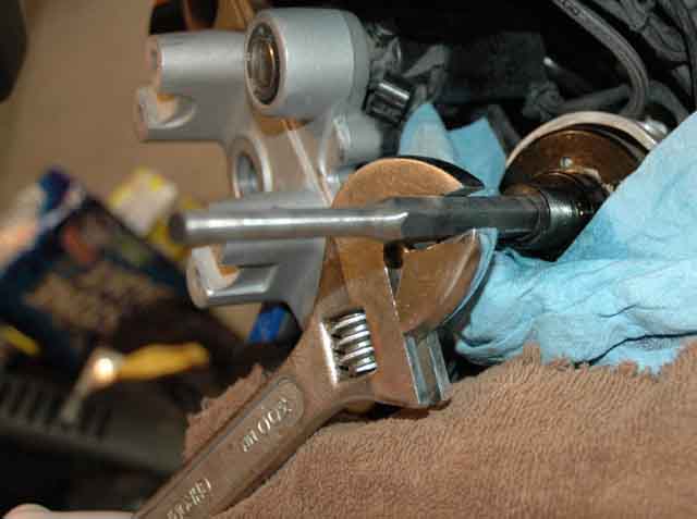
- Using the BMW special socket (Photo), remove the
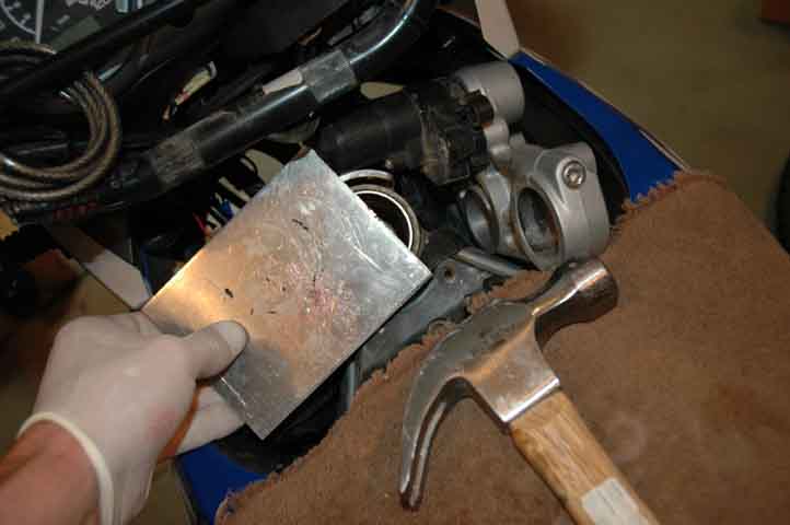
knurled, black anodized adjustment nut. Alternatively, use a large pair
of pliers, which will scratch the knurled edges slightly. Placing a
piece of aluminum sheet metal between the pliers and the nut will lessen
the damage (note that the damage is slight, and not very visible once the
handlebars are installed)
- The lower fork bridge (or "triple tree") of the bearing assembly
will now drop out the bottom.
- Using a machinist punch, drive out the bottom bearings.
Alternatively, grind off the sharp ends from a pair of nails and use these
to drive the bearings out
(Photo).
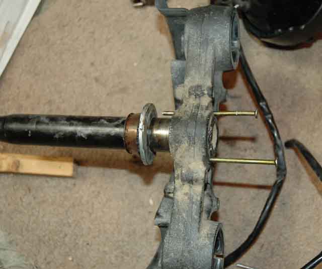
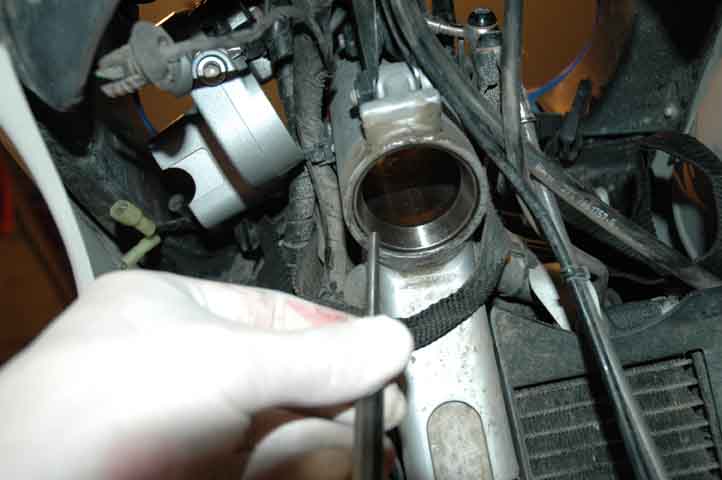
- Using a long machinist punch, or some other long metal object such
as a rasp file or screwdriver, drive out the outer races. Working from the
top, drive out the bottom race
(Photo).
Then, working from the bottom, drive out the top race.
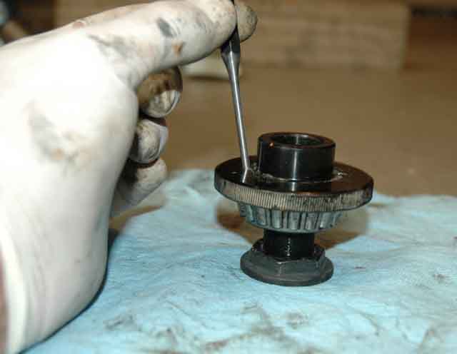
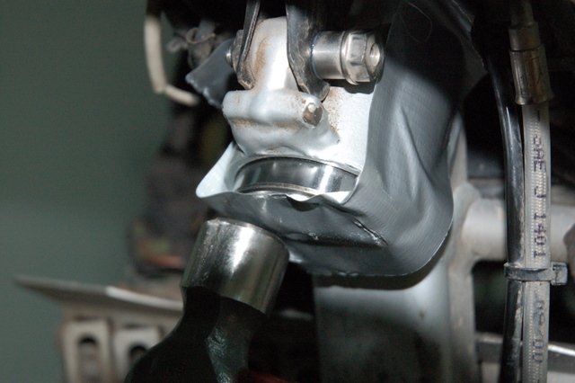
- Now remove the top bearing. Screw the counter pipe half-way in on
to the bottom of the adjusting ring, with the allen key-side
down, add the collar nut to the base if you like. Using a punch, drive
the bearing out
(Photo). A vice may be handy here, or at least a piece of wood to
drive against.
Steering Head Bearing Installation
- Using the old race, drive the new bottom race into place. I used
a piece of scrap aluminum to drive mine flush
(Photo of top
bearing race), then a punch to seat it all the way
(Photo).
You can tell when it's seated as it feels and sounds different than when
it is still moving with each blow. Repeat for the top race. Others (thanks NB) have found that a piece of duct tape
helps to hold the old race in place while driving it in. (Photo of bottom bearing race)
- Pack the new bearings in a good high temperature bearing grease.
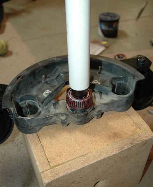
- Using a short piece of 1-inch ID PVC pipe (1.19" actual), drive
the top and bottom bearings into place
(Photo).
The cheap grade of PVC irrigation pipe fits just right. The heavier
Schedule 40 grade does not fit.
Re-Assembly
In general, re-assemble the bike following a reverse of the steps you
took to disassemble. We'll do this before adjusting the bearings:
general consensus is that you get a better adjustment if the weight of
the fork and wheel is loading the bearings.
- Slide the lower fork bridge (triple tree) back up into place, and
mate with the upper bridge. Before you do this, you might apply a good
layer of grease to the lower fork bridge shaft: good place to store extra
grease for the bottom bearing, which seems to go dry faster than the top
bearing. Thread the adjusting ring onto the shaft. No need to torque to
spec just yet as we'll adjust the tightness later on. Install the counter
tube, but leave it loose. Following adjustment you will install the 30mm
hex nut.
- Carefully slide the fork tubes back into place, inserting to the
original position. Tighten the lower fork clamp bolts; leave the top ones
loose as we will want them lose when we adjust the bearings.
- Install the horn and the fender. Torque as specified below.
- Install the wheel and brake caliper.
- Clean and grease the axle prior to installation
- Install spacer ring onto axle(right hand side of axle from
rider's perspective)
- Slide wheel into place between fork legs
- Slide axle into place, placing second (left side) spacer.
- Tighten axle to specified tork.
- Install the brake caliper and ABS sensor.
- Once assembled, check the ABS gap and adjust as needed
(0.1 to 1.0 mm)
Torque all bolts as specified below.
Handlebars
- Install the handlebars after adjusting the steering head
bearings (After Step 8 below). If you forget, you'll remember real fast
the next time you ride!
- Place handlebar in the clamp yoke and align with the masking tape
index mark. Install and tighten clamps and clamp bolts (from Step 1C
above, recall that they have a specific orientation). Don't forget to
torque as specified. The last thing you will do is install the ABS/heated
grip switches and the foam cross bar pad. Congratulations, you're done!
|
Tightening torques (from BMW manual) |
|---|
| Initial torque, round nut | 25 Nm (220 in-lb)
|
| Back off through angle of rotation | 60 degrees
|
| Counter-tube to steering head bearing | 65 Nm (575 in-lb)
|
| Hexagon nut to counter-tube | 65 Nm
|
| Clamp screws at fork bridge | 21 Nm
|
| Handlebars to fork bridge | 21 Nm
|
| Clamp screw, front quick-release axle | 21 Nm
|
| Front quick-release axle to fork leg | 45 Nm (From Dakar manual; GS manual says 80 Nm for this part!)
|
| Brake caliper to slider tube | 41 Nm
|
| ABS sensor to bracket | 9 Nm
|
Adjusting the Steering Head Bearings
The BMW shop manual provides torque values for the adjusting ring.
However, unless you have the special BMW socket, you cannot torque the
ring. It seems there is a general goal in mind: the bearings should be
just tight enough to allow the handlebar to move left or right under it's
own weight, but not TOO loose. Below are three descriptions to help you
achieve this goal. The first method is from the BMW manual, while the
second two methods are methods that do not require the special BMW
socket. Note that correct torque values cannot be achieved without
the socket.
Adjusting the Steering Head Bearings (From BMW Manual)
- Slacken round adjusting nut with pin-wrench adapter,
BMWNo. 31 6 521, then tighten to 25 Nm.
- Turn forks back and forth twice from lock to lock,
and leave the forks at the full left lock position.
- Mark a 40 mm (1.58 in) arc with adhesive tape or
similar (arrow) around the circumference of the
locking plate at the steering head.
- Align the mark on pin-wrench adapter,
BMWNo. 31 6 521, with the right-hand end of
the marked arc.
Note: 40 mm (1.58 in) around the circumference of the
locking plate corresponds to an angle of rotation
of 60°.
- Turn the round nut clockwise until the pointer on
pin-wrench adapter, BMW No. 31 6 521, reaches
the left-hand end of the marked arc.
- Remove the mark/adhesive tape from the locking plate.
- Check the mating faces of the fork bridge and
knurled nut, rub down with an oilstone if necessary
and clean.
- Tighten the counter-tube.
- Install fork bridge.
- Firmly tighten locknut.
- Tighten the clamping screws of the fork bridge.
- Check play and freedom of movement.
- Lift front wheel clear of the ground and perform final check:
- With the front wheel off the ground, the weight of
the forks must be enough to turn the steering all
the way to the left and right full lock positions as
soon as the handlebar is moved away from the
straight-ahead position.
- If local points of stiffness are detected when the
handlebar is moved to and fro, renew the steering
head bearings.
Adjusting the Steering Head Bearings (By Flash, #412)
- Tightening Steering Head Bearings - 101
Tighten the lower nut until it is pretty tight. Move the forks back and
forth, lock to lock a few times. They SHOULD feel too tight. These are
tapered roller bearings and need to be preloaded a little bit. But not
THAT much. Back off about a sixth of a turn. Do the forks flop by their
own weight (wheel installed, tire not in contact with the ground) when
you knock them just a little off center? If so, that is TOO LOOSE.
Tighten it up just a skosh. When you give it a good TAP, it should turn
to the lock and then bounce slightly. It might do one side better than
the other due to cable tension. When the triple clamp and handlebars are
installed, does it STILL behave this way? It might have tightened up when
the top clamp nut was tightened. If it is just a LITTLE bit too tight,
take it for a ride. It will loosen up slightly with some use and some
wear, but not much. If it is certainly too tight, DO NOT RIDE. Pull the
clamp off and loosen the nut 1/16 to 1/8 of a turn and try again.
Adjusting the Steering Head Bearings (From by Oyvind #1052)
- The manual states that the adjusting ring should be tightened to
25 Nm, and then slackened 60 degrees, or 40mm as measured around the
circumference of the ring. This is pretty hard to do w/o the proper BMW
tool, though. I guess the idea is to just tighten the adjusting ring up
good to make sure the bearings are properly seated, and then slacken
until the steering moves freely. It's probably a good idea to reattach
the fork and front wheel before adjusting, since the most important
criteria is that, with the front wheel off the ground, the weight of the
wheel and fork must be able to turn the steering all the way to the left
and right full lock position. I tightened the adjusting ring until the
steering just couldn't move by itself, and then slackened it just a
little more than needed. The latter is important, since the
steering will tighten up just a wee bit more when the counter pipe is
tightened.
Feedback
- At 35 000 km, the SHBs of my Dakar were severely notched, and
steering had become difficult. After checking the flat rate for the job
at my dealer, and not least the waiting period now at the height of the
season, I decided to have a go at it.
This post is chiefly about the differences between the classical SHB FAQ,
and the GS SHB.
1. The bearings and sealing discs have been changed. The bearings are
generically known as 28x52x16 X. The sealing discs are made like shallow
"cups", and are all metal. I can post the part number later, when I get
home and find the small bag they came in. They are sold in a set of two,
and are fairly cheap.
2. I got my bearings from an industrial supplier, but they charged just
about the same price as BMW asked for their bearings. You may want to
check this out for yourself, and add in the added hassle and cost of
visiting several shops to gather all you need for the job, in the
equation.
3. The "slotted ring" described in the classical FAQ has been replaced by
a knurled "adjusting ring". No C-spanner will work here! After loosening
the "collar nut" on the upper fork bridge, use a large allen wrench on
the "counter pipe" in the center. I didn't have any allen wrench that was
that large, but the hex handle of a large dowel, combined with a wrench,
did the job just as well. You may also take use the head of an
appropriately sized metric bolt, screw two nuts on the bolt an use that
for a replacement. Anyways, unscrew the "counter pipe" before loosening
the "adjusting ring". The "adjusting ring" has two small holes on the
surface. These are intended for a special BMW tool (surprise!) with two
small prongs. I used a small dowel (machinist punch) in the holes to
loosen the ring. The lower part of the fork head will now drop out. The
top SHB is attached inside the "adjusting ring". The lower SHB stays on
the lower fork head.
4. Standing there with the adjusting ring, complete with SHB, in your
hand, you may now feel panic creeping in on you as you realize that there
are simply no ways to get a hold on that bearing. Do not despair!
Screw the counter
pipe half-way in on to the bottom of the adjusting ring, with
the allen key-side down, add the collar nut to the base if you like.
Clamp your allen wrench, or whatever you used to unscrew the counter
pipe, in a vertical position in a vise, and put the adjusting ring et al
on top of that. You now have a sturdy base for working on getting the top
SHB out. The inner race of the bearing is driven out by using another BMW
special tool (surprise again!) through the two small holes in the
adjusting ring. I didn't have that, so I welded up an appropriate tool
using a large, surplus socket of an appropriate size, and two hardened
steel nails. However, you can probably just use a small dowel and
carefully work both sides. The manual states that the bearing does not
need to be heated, and this is absolutely correct; no need for burnt
fingers here!
5. If you look carefully at the bottom of the lower fork clamp (you may
have to scrub off the dirt), you'll notice two smallish holes here, too.
Wonder over wonders, you can drive out the inner race of the lower SHB
using the same dowel, and procedure, as for the upper SHB! Piece of cake.
If you think that your puny little dowel is far too short to drive that
bearing all the way down the shaft, don't worry. The shaft tapers gently,
so it only has to be driven 1-2 inches before loosening.
6. The outer races, which are still attached to each end of the fork
tube, are easily driven out with a large dowel through the tube.
7. The inner races were fairly easy to drive home using just a thin dowel
and some cooling, or icing, spray on the inner parts. Installing the
outer races in the frame tube was also fairly easy, chilling the races
with icing spray before, and during, the installation.
8. The manual states that the adjusting ring should be tightened to 25
Nm, and then slackened 60 degrees, or 40mm as measured around the
circumference of the ring. This is pretty hard to do w/o the proper BMW
tool, though. I guess the idea is to just tighten the adjusting ring up
good to make sure the bearings are properly seated, and then slacken
until the steering moves freely. It's probably a good idea to reattach
the fork and front wheel before adjusting, since the most important
criteria is that, with the front wheel off the ground, the weight of the
wheel and fork must be able to turn the steering all the way to the left
and right full lock position. I tightened the adjusting ring until the
steering just couldn't move by itself, and then slackened it just a
little _more_ than needed. The latter is important, since the steering
will tighten up just a wee bit more when the counter pipe is tightened.
9. I picked up a cheap pack of assorted dowels years ago, and they proved
invaluable for this job. Also, there's a lot to be said for icing spray:
It cools down just what you need, when you need it. No need to go running
back and forth between the freezer and the garage. It can bring the
temperature quickly down to -50 deg C (that's COLD). And last, but not
least, it's a lot safer than heating when you have a choice between the
two. Available from electronics suppliers and probably also some auto
parts stores.
One more thing: The manual states that the surface of the adjusting ring
must be perfectly even before mounting the upper fork bridge. If you
misformed the two small holes when using a dowel on them, rub the surface
down with a fine oilstone to make it perfectly even, and wipe the surface
clean with a rag. Oyvind #1052, '01 F650GS Dakar, Bergen, Norway
- Thanks for the notes on your work. I recently serviced the SHB on
my 2001 Dakar (5000mi). I went ahead and bought the special socket (pin
wrench) to do the work (from Chicago BMW). I followed the instructions on
the maintenance disk and torqued the bearing to specs , then backed the
nut off 40mm (140mm?). After all this expense and effort I sat down for a
good laugh. The BMW instructions could be surmised as tighten the
adjusting nut till the steering becomes hard to turn, then back off the
nut 1/4 turn. Sounds just like adjusting the wheel bearings on my Momma's
old Pontaic. BTW, I didn't see any signs of original grease in the SHB
melting. There also seemed to be enough grease. I could see some wear
(shiny spots) on the lower bearing. I went ahead and cleaned the bearings
and changed the grease. One other thing...My lower bearing had a cage,
but is was a separate piece from the bearings and races. By that I mean
when I cleaned off the old grease, the cage and bearings came apart. If
this is normal (and the bearing ain't broke), you want to be careful
where you clean the bearings so that you don't lose any parts ;o).
andy112652, CG#1481, IBA #7647, '01 F650GS Dakar, Columbia, SC.
- At 17,500 miles, my steering had become "indexed" with what felt
like a notch in the straight-ahead position. Once removed,
the top bearing looked good;
the bottom was broke (i.e., the rollers fell out of the assembly when
removed). It could be that
driving
them out with a pair of ground-of nails (or a machinist punch) caused
the damage, though the top set was OK. I replaced both sets of bearings.
Total time was about 3.5 hours. I used a pair of BR-32 bearings that I
purchased from Schucks Auto for $19.99 each. I re-used the "spacer" dust
caps: they were slightly dented from the machinist punch, but decided
they were OK to re-use.
I rode 1,000 miles the next few days, and found the ride to be very
squirrely, even dangerous when passing trucks. The bearings were too
loose. When I adjusted them, I used the "let the bar swing" method of
calibration, and I think I let it swing too easily. Also, I think the
top fork clamp bolts were too tight, so my adjustment efforts were not as
effective. I re-adjusted, so the bar just barely swings under its
own weight. This seems better, though only time will tell.
Scott , ID #1244
- I'm in the process of doing mine now. All of the info was great,
and very to the point. I do have 1 thing to add though. After whacking
for an hour or so trying to get the top bearing off the adjusting nut, I
took 2 long, but skinny bolts that fit perfectly in the holes. set the
contraption sideways in the vice and tightened it. 2 seconds later that
bearing was off.
My bottom bearing fell apart upon removal. The top seemed to be ok. the
grease had mostly disappeared from the bottom bearing, and there was a
good amount of dirt in each.
I thought I could reuse the dust caps when I was finished. No chance of
that, so now my bike sits for an unspecified time with the front end off,
while all the parts are laying all over the garage just waiting for
someone (me) to lose them.
gstlanta, '01 F650GS
- With the help of Raymo's socket, I replaced my SHBs this weekend.
Not too tough, it ended up taking about 4 hours, with two runs to the
hardware store included. Here were the parts that had me scratching my
head:
1. When you're disassembling, note the routing of the cables around and
through the forks. it makes reassembly easier.
2. It's helpful to have something around (i.e. a milk crate) to have the
forks rest on after you've removed the front wheel and are dropping the
fork tubes (and lower triple clamp). That way, you can rest the forks
there while you disconnect the fender, so you can get to the horn to
disconnect it. Alternately, I suppose you could drop the fork tubes
completely out of the triple clamps. That's not how I did it.
3. Getting the lower inner race off the bottom of the triple clamp. It
wasn't until I reread raymo's entry in this thread that I understood what
to do here. There are two holes that run all the way through the bottom
of the triple clamp. These allow you to take a 3mm drift and push the
dust cap and the inner race off the triple clamp.
4. Getting the upper outer race off the "special" nut at the top of the
assembly. The holes that the pins on the special socket slip into go all
the way through this nut. You can use the same 3mm drift to tap the dust
cap and the upper outer race off the nut. It's nice here to have
something relatively soft, like two 2X4's, to rest the nut on. Or, you
could screw the nut back onto the top of the triple clamp assembly, rest
the fork legs on something soft like a piece of wood, and tap them out
that way. This is what I did, after we broke a drift trying to tap out
the race with the pieces of wood lined up incorrectly. NOTE TO FLASH:
although replacing the special nut with the old F650's slotted nut sounds
tempting, it would leave you with no way to tap out the upper outer race!
Looks like we're kinda stuck with using this $54 tool.
Another note with race removal; although I chilled mine in the freezer, I
don't think it was necessary. They went in pretty easy, and the old ones
came out without the use of a torch.
5. It's easier to reconnect the fender and the little black skirt that
the horn attaches to when the fork tubes are partially dropped.
Otherwise, it's tough to get in behind the headlight with the torx
wrench.
All in all, the job wasn't too bad. Many thanks to Raymo for the special
tool (I'll be sending you an e-mail very soon about its return) and to
everyone for their advice. Robin, #790, '01 GSD
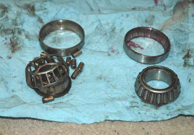
- The "spacer" (I would call it a shield.) is just a metal cup that
each inner race rests in. It looks like it does a good job of keeping
rain and dirt away from the bearing. Two required.
The socket serves the same purpose as the C-spanner does on the Classic.
The service manual calls for torqueing the nut to 25NM, then backoff 60
degrees (Actually that's what it SHOULD say; There's a typo in the
manual.) This resulted in the handlebars being just ever slightly tighter
than with the worn bearings.
Raymo #1173, Chicago, 2001 F650GSA
- My SHBs lasted 29K miles.
Tools that I already had:
Standard metric sockets, torque-sockets, hex-sockets, 30mm socket
(1-3/16"), carpenter's hammer, torque wrenches, small-drift set
Tools I needed to buy:
12mm hex key (+ persuader pipe), BMW speciality socket, 8" x 1/4" drift
The socket cost $52 at Chicago BMW (20% off). I still saved money, no
doubt.
If you want to follow the BMW procedure of torqueing the bearing to 25NM,
then backoff 60 degrees - you'll need the socket. A pipe wrench could
turn the nut, but you would scratch the edge of the it (cosmetic only).
With a grinding wheel and drill press, I'm sure something equivalent to a
C-spanner could be fabricated.
Raymo #1173, Chicago, 2001 F650GSA
- Raymo, what does this tool do? Please make a picture of it
available before you let it out of your hands.
Flash, #412
(Diagram of BMW Tool)
(Home made version
by haakon)
- Flash - It's the equivalent of a C-spanner, just more expensive.
But seriously now, it's very similar to a 3/8" drive socket. Differences
are:
1) It has a groove cut around the outer circumference. In that groove is
an O-ring and rotatable metal pointer. The O-ring provides friction for
the pointer, thereby preventing the pointer from drifting away from where
you've set it.
2) The working edge of the socket has two pins set 180 degrees apart
(each pin is about 1/16" diameter by 1/16" long).
3) The inside of the socket is round, not hex.
The surface of the "round nut" (formerly known as a "slotted nut" on the
Classic) has two holes spaced 180 degrees apart. The two pins on the
socket engage the two holes on the round nut. After the round nut has
been removed, these two holes are then used along with a drift and hammer
to drive the upper inner race off the round nut. (Yes - the upper inner
race is pressed onto the bottom of the round nut.)
During installation of the round nut, the BMW service manual calls for
torqueing the round nut to 25NM, then backoff 60 degrees. The rotatable
pointer (along with 40mm tape) is used to measure the 60 degree
backoff.
Since I've never changed SHBs before, I don't any reference experience
when adjusting the SHBs. I must say that by using the socket it was nice
not to have to play "Goldilocks" over again. Did I adjust the SHB too
tight, too loose, or is it just right? With the socket, the load can be
set quickly and brainlessly. (Insert your own comments here about BMW
techs.)
For a first-time SHB change, I found it comforting to be able to set the
load on the bearing quickly and objectively with just a torque wrench and
some tape (oh yea - and a $52 socket too).
Raymo #1173, Chicago, 2001 F650GSA
- Thanks for the data. I just called NAPA: they only stock the CR
brand bearing for $24.04 each. BMW wants about $28 each. Schucks Auto
also has the CR brand, at $19.99. Schucks guy tells me SKF probably makes
the CR bearing.
Scott, ID #1244
- CR stands for Chicago Rawhide which dates back to when they used
to make bearings out of the leftovers from the Illinois beef industry
(hides). I've checked them out and they appear to be high quality
bearings.
My NAPA bearings came in a box that said "Made in Japan". I pulled them
out and they were SKF with "Made in Germany" clearly printed on the outer
edge of the race.
NothingClever
- The Advance Auto Parts store here in the USA carries these
in the NTN brand, Japanese manufactured and high quality. The box was a
Federal Mogul box. (Whatever...)
I'm having good luck with them on my wheels and sprocket carrier. No
graunchies in 16, 100 miles. Changing them out anyways here pretty soon
as routine PM.
Hopefully these NTNs will last longer than the SKFs. I'm pretty amazed at
the poopy head tube angle. Great on road comfort but tough on steering
responsiveness and bearings when ridden over varying surface conditions.
(A subsequent comment by NothingClever)
- The thing about installing bearings and races is that you never
want to apply force THROUGH the new bearing. There's no point in
brinelling a perfectly new bearing just to install it. If you are driving
the inside race on, you want to be applying force on the inside race. If
you are driving the outside race in, you want to be applying force on the
outside race. This is why one of the best tools you can use is the old
race itself. It is EXACTLY the same size as the race you are moving.
Races are VERY hard and you can wail on the old on in order to move the
new one. Be sure to orient an outer race the same as the one you are
driving. This will afford you a "lip" with which to drive it back out if
necessary. As NC mentioned, the steering stem is relieved along all of
its length but where the bearing itself actually sits. So there is no
problem there. A piece of pipe works to drive the bearing onto the stem.
A handy-sized socket works to drive the races home.
Flash #412
- Regarding the removal of the triple-tree bearing on the GS:
As Flash has pointed out, you need a small diameter punch, with a long
reach. Unfortunately this combination is likely to bend the punch.
As I was whackin' my bearing off, I realized the punch was too short to
go through the triple tree and still push the bearing off the triple
tree. I found a large diameter nut that I could use as a spacer. I turned
the nut sideways, and put it between the halfway-removed bearing and the
triple-tree.
This allowed me to use a punch with a shorter reach, and is less likely
to bend the punch.
Raymo #1173, Chicago, 2001 F650GSA
- Note: I ground the sharp point off a pair of 3" nails and used these as punches to drive the bearings out. Worked fine and cost essentially nothing. Scott, ID #1244
The nails didn't work for me to drive off the upper and lower bearings.
Flash and I went through a good half dozen. My inner races must've been
frozen. Most likley a rare incident as others seem to be having greater
ease than what I did. NothingClever
- I would also like to point out an error in the BMW service manual
that states that you should tighten up the bearing to (I think 25nm),
make a mark 60 degrees back to the left, then to turn CLOCKWISE until you
reach that mark. It should read counter-clockwise, so that you are
loosening the nut, not tightening it. Makes a difference. -SScratch
What's a Tank Slapper?
- Tank slapping refers to the wheel (and attached handlebars)
swinging violently from side to side, due to a harmonic reaction to
steering input or poor mechanical condition. Steering dampers were
developed to prevent this problem (that can get you killed). I had a 1985
R80 that I converted to an R100RS. If the steering bearings got a bit
loose and you hit a rock while leaned over, or if you took one hand
off of the bars at around 40 mph to reach the reserve tap, it would
result in a tank slapper. I thought I was going to die a couple of times.
The front wheel left skid marks on the pavement, as the wheel turned at
45 degrees to the direction of travel, while the bike ploughed ahead.
Fortunately, I was able to stop the bike without falling over, or getting
hit by an oncoming car. I am now anal about steering bearing tension. (I
also noted that my R80 rear shock was longer than the later R100RS bikes.
I think BMW reduced the rake of the forks by lowering the rear of the
bike, when they bolted the RS fairing to the single sided swingarm
airheads. This would make the bike more stable.) -Richard #230, Marty
#436, Noel, Iceman #975 December '01