Flaying the VR
compiled & edited by Kristian #562
Please read the Disclaimer before
attempting any work in this FAQ.
Last Updated: 27 April 2007, by Winter #1925
Other relevant FAQs:
NOTE: This FAQ is now obsolete. If you are reading it, stop reading now as there is a far better solution (see the note below). This FAQ remains available on the website as the solution suggested in this FAQ may still be useful if you are stuck in the middle of nowhere and do not have access to spare parts / a GS VR.
| Better Solution: Install a GS Voltage Rectifier |
|---|
| There is now a far better solution to the VR problems associated with the Classic VR. Install a GS VR as discussed in the Voltage Rectifier FAQ. The GS VR is a much better alternative, and should also be relocated (as per the installation instructions in the VR FAQ). This FAQ is provided for Information Purposes only. It is HIGHLY recommended you install and relocate a GS VR |
Since the first issue of this FAQ, Hombre sin Nombre has come up with a modified version, called Flay 2, details of which are described below, along with reasons for the change. However before you launch into this (admittedly much cheaper solution), consider the (as yet untested) alternative of a SEALED BATTERY. Why?
Perhaps we don't really need a VR Flay - we need to replace our wet cell battery with a Maintenance Free battery - the voltages I'm seeing (both Electrex and OEM) are perfect for gel cell (AGM) Maintenance Free batteries. BMW just skimped on the extra $10 it would cost them at the factory. Gel cells don't take a full charge until you exceed 14 volts, wet cells are happier staying below that. In the old days when MF batteries first came out, people complained that MF batteries in older cars didn't last long - because they never fully charged well. And older style wet cell batteries dried out due to overcharging when used as a replacement for a MF battery in a newer car. Screw the Flay - anything under 15 volts, just go for a MF battery. (I don't go for turning MF batteries on their side though - they DO have vents, and WILL leak nasty stuff if overcharged and overheated.)
The flay doesn't "bypass" the VR. The modification simply connects the VR's REFERENCE point to your battery as directly as possible, instead of routing it through six or eight feet of small wire, three or four connectors and a switch. If the VR is LOOKING at your battery, then it will do it's dead level best to actually make your battery sit at the RIGHT voltage, which is already high by normal lead-acid battery standards. If your wiring and connectors are dropping a volt or two... then your battery will FRY. This was the inspiration for the genesis of the VR Flay. Thanks to HsN for that little piece of genius.
by Hombre sin Nombre, Flash #412 and JOD in Oz, March '01
This proposal arose as a solution to high charging rates measured at the battery, as discussed in the Voltage Rectifier FAQ and the resultant effect on the battery, with a subsequent loss of water, and on the wires particularly the yellow ones to the VR, which have been observed to get very hot and almost burn out.
The flay doesn't "bypass" the VR. The modification simply connects the VR's REFERENCE point to your battery as directly as possible, instead of routing it through six or eight feet of small wire, three or four connectors and a switch. If the VR is LOOKING at your battery, then it will do it's dead level best to actually make your battery sit at the RIGHT voltage, which is already high by normal lead-acid battery standards. If your wiring and connectors are dropping a volt or two... then your battery will FRY. This was the inspiration for the genesis of the VR Flay. Thanks to HsN for that little piece of genius. (We lost him when the forum software changed to be slow-modem UNfriendly.)
This is JOD's original problem and solution:
Got sick of adding water to battery after each
long ride. It is also hot here in Oz. Did some testing on the voltage regulator
and found that it does actually regulate better than we thought. Trouble is the
voltage sensing wire is the green wire that comes from front of bike and it sits
on 14.2 volts, while the regulator output wire (big red/white wire) is at 14.8
volts which is enough to boil the battery 'cos it is electrically close to VR.
Seems the difference is voltage drop from VR through loom to front of bike,
through switches, then back to VR. This 0.6 voltage difference would be made
worse by poor connectors, and is exacerbated by more electrical load like
cooling fan running etc. I've added a little relay at output of VR so it "sees"
the voltage going to the battery, which now regulates to about 14 volts. Battery
seems happier and after a 2000km weekend recently no water disappeared!!!
F650 - 1999 model. What I did was cut the green wire to the VR and insert a 12
volt relay that comes in when ignition is turned on. i.e. coil is between
green wire from connector and earth.
Relay N/O contact is between VR output wire (red/white)- (don't cut this wire,
just join into it) and green wire to VR. i.e.: when bike is running, VR sees it's
own output instead of sensing the volts from front of bike. It then regulates
it's output to 14.2 volts instead of the volts at front of bike to 14.2. The
battery now gets about 14.1 volts (14.2 less a bit of voltage drop) while the
front of bike gets about .6 volts less : 14.2 - 0.6 = 13.6 volts. Still plenty
to run lights etc.
I've tested for a couple of months and battery seems to be holding full charge, but not boiling water any more.
The relay was a standard head light relay I had lying around, over rated for the job 'cos it's only switching milli-amps i.e.: the VR feedback signal. Relay is about 1 cubic inch in size, and available from any auto accessories shop. The coil of the relay does not go to the VR. It is just across ignition. The N/O contact goes to the VR sensor.
I've been out of touch for a couple of weeks. I've since had to delete the connector on the VR to Alternator yellow cables. You're right about them being undersized - probably made worse by 'lights on' legislation. I replaced the triple wire connector with soldered joints 'cos it was getting real hot. There is no way that connector could handle rated output of alternator (280w) indefinitely. Suggest others drag it up to the surface to check it's condition.
Detailed Description of Modifications Required - Flay I:
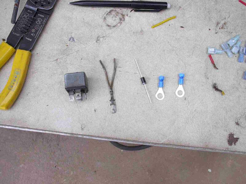
Parts:
You will need:
Method:
Notes:
The RELAY has 4 Contacts: The numbers are the ISO DIN Numbers.
30. The Common Contact (Also Normally Open)
=> Green wire (cut) from the VR.
85. The Ground Contact (Coil) => Ground.
86. The 12V Coil Contact => Green Wire (Cut) from the Wiring Harness.
87. The Normally Open (NO) Contact => New Wire which is in turn spliced into the
Red/White Wire (from the VR).
Q. How does Joe Bloggs identify these 4
Contacts on the Relay.?
A. Joe Bloggs will need to read the PACKAGE that his relay came in, or
look at the PICTURE on the relay body.
Refer to this resource on Relays:
http://www.mgcars.org.uk/electrical/body_relays.html
Q. Do you have a Picture of the wiring
you need to do.?
A. Sure. Have a look at this
Diagram. Note the BROWN Ground wire coming out of the VR is NOT shown in this
Diagram.
Q. What happens if the Relay Fails. How
do I get home.?
A. You are STRONGLY ADVISED to make and carry around a little jumper in case
the relay fails. A bit of wire with a couple of male spades on it can be used to
jumper between 30 (green wire) and 86 (green wire) to restore the system to it's
original condition in the event of relay failure. The SAME jumper can be used at
the fan switch to turn the fan on for testing purposes.
Q. Why can't you just put more lights
on etc. to lower the Voltage. ?
A. Because that has the opposite effect.! The way I understood
it things like leaving your High Beam on and adding any accessories basically
helps cook your VR and your battery, because to supply 12V to the Lights
'way-up" the front there, (with all the associated losses due to poor
connections etc) the VR has to (via control of the Alternator) pump out maybe
14.8 or more Volts close to the battery, which overcharges it AND fries the VR.
So assuming that's correct, then putting the High Beam on will exacerbate the
problem, not relieve it. That's pretty much how it works....the headlight is
"far away" (long thin wires, bad connections) from the VR output, and the VR
voltage sensing wire is even further past it on the loop of wire from the VR
output to the headlight back to the VR (voltage sensor input). Add in load from
the fan and brakes, and the voltage actually reaching the VR sensing wire drops
considerably, so the VR tries to make up for it. It might work OK with just the
headlight load, but the fan (and brakes) overload the small wiring. If the wire,
connectors and switch contacts were twice as heavy, there would be no problem to
discuss.
Q. I have a Hella 30A
12V relay from the engine compartment of my parts 2002. Will this work?
A. Yes.
Q. If I already have a plug for a battery tender wired to my battery can
I just use it to plug in the new ground from terminal 85 and the voltage monitor
wire from terminal 87?
A. NO.! You want to wire this thing in there PERMANENTLY, not on a plug. You
want this to get a reasonably good ground and a PERFECT CONNECTION to the +12V
side of the battery.
Discussion:
If I were to install such a relay, I would put a 1N4001 diode backwards across the relay coil. The flat of the triangle (anode) goes to the ground end of the relay coil and the point of the triangle (cathode) goes to the (switched) +12V end of the relay coil. Why? Because a coil stores energy in the form of a magnetic field that is returned as current just as a capacitor stores energy in the form of an electric field (voltage) that is returned as current. The current through a coil can NOT instantaneously go to zero. If you are LUCKY, when you switch off the key, the energy will be dissipated in the arc across the open contacts of your ignition switch, which is not at all good for long switch life. Why is that LUCKY? Because if the energy is NOT dissipated in your ignition switch, it will appear as an ARC INSIDE YOUR VOLTAGE REGULATOR via that green wire you hooked to the relay coil. The diode costs less than a dollar. I could be wrong about the need for it. It's your US$250 regulator at risk, not mine. If I make this mod, you can bet your ass that mine will have the freewheeling diode bassakwards across it.
If you wire the "VR-sense" to the battery, then the thing is "running" all the time, even when the system is off. That is the point of the Ozzie's relay. You turn on the key and NOW the VR sees it's output at it's input. But, since it's output is tied to the battery... it IS looking at the "storage tank."
And it would be nice if we could stick a diode (check valve) in the green wire so there would be no backflow when everything is turned off, and connect it to the r/w wire (battery) all the time (bypassing the ignition switch), but the diode would lower the reference voltage by about 1.2 volts, and since the entire problem we're having is not getting a proper system voltage at the green wire.....that's not a good idea. Though it would probably work quite well if we were able to adjust the VR output to compensate. So the relay works quite well, connecting the wires when we want them, and disconnecting them when we turn everything off.
Regarding the freewheeling diode on the VR-relay project... I don't *think* that those small signal jobbies like the 914 and 4148 will last very long. And the thing is, if they go, you won't ever know cuz they'll OPEN. Go ahead and get the 1N4001 Big-Ass(tm) Diode UNLESS you measure the coil resistance and determine that the quiescent coil current is less than the rated current of the li'l feller (with a safety margin thrown in for engineering soundness). Cuz THAT is exactly the current that'll freewheel through the diode when you open the switch. And the signal diodes are rather limited. I just hate having to order two 17 cent items of the Perfect Part.... so the funky low tech Big-Ass(tm) component it shall be.
In this case the ignition switch is there, isolating the two positive wires (r/w and green) so that the system completely shuts off when the ignition switch is turned off.
Summary: This fix is fairly easy. Obtaining the various electrical bits is probably the hardest part. I realized about a .55 volt reduction in voltage charging the battery at 4,000 RPM with only the low beams on. Increasing the load on the system had little effect until overload occurred. A very stable voltage of between 14.30 and 14.38 volts was obtained after the fixed, again at 4,000 RPM. I was able to scavenge almost all electrical parts other than the diode and various connectors, from an old BMW auto I have laying around. This document assumes you have printed the latest diagram hand have it handy.
1# 12V 30A relay
6# Female Spade Connectors � insulated or covered
1# Long Male Spade
Connector with retention tab similar to the stock male connector on the green
wire from the VR to the harness.
(You can bypass this method if desired by
not using the original connector for the green wire.)
1# 3A diode � loose
2# � inch stud connectors. They look like lollipops with holes in them, similar to the ground connectors on the frame nearest the fuses.
3# feet of #12 wire though #14 would probably be fine. I am always accused of overkill. I would just get some green, red and brown.
?# feet of electrical tape and/or shrink tubing, whatever you like.
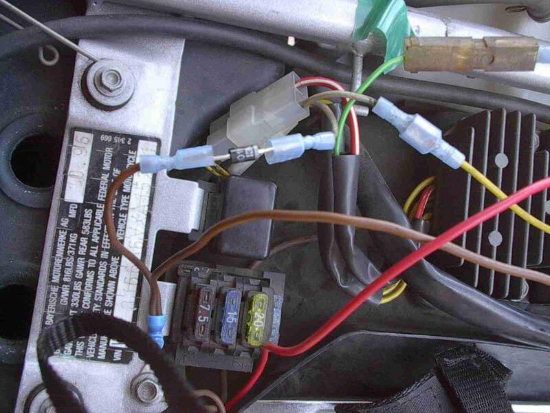
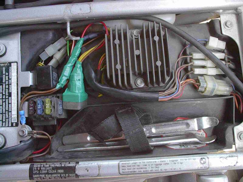
I did not cut the green wire. In fact, I cut no stock wiring. I did each wire all the way before moving to the next. I laid the relay in between the VR and the back of the bike in the back part of the under-seat tray and tried to keep the wiring the same length so that when I was finished I could wrap the end of it up, including the relay and push the wires in an �S� fashion so that I could eventually just lay the relay down where it would be out of the way.
So, starting with the VR side of the green wire, disconnect the plastic connector that connects the green wire and the red/white wire to the rest of the harness. Reach down into the plastic housing with a small screwdriver and depress the metal tab on the long male connector and remove it from the housing.
Get about a four inch length of green wire with a female spade connector on each end and used it to connect the long male end of the green wire with terminal #30 of the relay. Tape or shrink-tube the male/female connection between new and stock wires.
Make a long male connector with two green wires coming out of and connect it to the now vacant half of the connector I mentioned in number two. You can use a regular male connector and just crimp two wires into it and bypass the stock connector, but you will have to take out the female connector. From this two wire connection to what was once the VR side of the plastic connector, take one wire and connect it to terminal #86 of the relay using a female spade. Solder the second wire to the end of the diode with the band at the top of the barrel facing the two-wire connection, not the ground. To the other end of the diode solder a wire that will become the ground (you can use one piece of shrink tubing to cover the whole mess). I would use brown wire for this.
Take another piece of brown wire 6-8 inches long and along with the ground you created in #4 crimp both wires into one of the � in stud connectors and attach this sandwiched with the two others at the ground point mentioned in #5 in the Bill of Materials section above.
Take the long ground you just created in #5 and connect it to #85 of the relay using a female connector.
Get some red wire and crimp onto one end the remaining � inch stud connector. Thread this wire from the �+� terminal of the battery alongside the main bunch of wires going to the fuse bus and then connect it with a female spade to #87 of the relay. Tape everything up or whatever and then connect the stud connection to the battery. Fold the wires and relay in such a way as to lay nicely and you�re done!
 |
 |
 |
 |
I am sure there is a neater way to do this way seems to work. I did make a wire with the appropriate connector on each end so that the relay can be bypassed in case the relay fails.
OK, so here's the before and
after Voltage Results at the rpm shown. If you FORGET to take the readings
before, Just pull the two green wires off the relay and connect them back up
together again while you make the measurements. (Flash #412)
After Before
Idle - Low Beam 14.40 14.65
Idle - High Beam 14.43 14.79
Idle - Plus Brakes 14.45 14.96
Idle - Plus Horn 14.45 14.80
4000 - Low Beam 14.38 14.95
4000 - High Beam 14.33 14.85
4000 - Plus Brakes 14.30 14.65
4000 - Plus Horn 14.30 14.85
VR Mod Update
So, while doing the 18K service I pulled my battery to top off the water and
clean it and found that even though I put in the modification to slightly reduce
voltage going to the battery while riding that in just a 1000 miles I had a
couple of cells down to the "low" line and had to add water to four cells total.
I will now put some heat shielding in and see whether this will reduce the
evaporation as the affected cells were the ones closest to the muffler/cat.
Muriel #582 in Vermont
A friend followed the FAQ, and flayed my VR. His comment was "These guys put
together some good stuff." We checked the readings after, and at idle is was
14.22-25, and at 5,000 rpm it was about 13.71. My battery was overcharging and
boiling out the water kind of often. The remedy is to Flay the VR - see FAQ) Now
it is shutting down the charging sooner (best I can explain).
Shank NYC USA
The idea is to reduce the voltage. Using extra lights just sucks down more
amperage and your battery still gets cooked. I wanna reduce the pressure
(voltage), not the output (amps). With extra lights, heated vest, etc. you are
sucking down more output (amps), no matter what the pressure (voltage). And if
you suck down more output than the alternator is capable of giving, it takes
output from the reservoir (the battery), no matter what the pressure (voltage).
It's the pressure (voltage) that cooks the battery dry. I wanna keep all my
output (amps) but decrease the pressure (voltage). Sucking down more output
ain't gonna decrease the pressure. It's the pressure that's got to come down and
that's what the VR flay does. We have a 280 watt, 20 amp charging system (in
this case, we can use watts and amps interchangeably).
Given: It's the voltage that cooks the battery, the more volts, the faster it
cooks. Warmer weather does not help. Neither does the battery's warm locale next
to the catalytic converter/muffler.
If you ride the bike with no extra draw, you may only use 180 of the 280 watts
but the voltage remains the same, thereby cooking your battery.
If you add accessories and are now using ALL 280 of the 280 watts available, the
voltage remains the same, thereby cooking the battery.
Get a digital volt meter (Radio Slack has a very nice compact one for $25, part
# 22-179A). Measure the DC voltage at the battery while the bike idles (put the
red lead on the positive battery pole, the black lead on the negative battery
pole, ya only need to take off the seat to do this). If it is above 14.4 volts,
you will cook your battery. Now rev the engine up to 5000rpms (yes, it will
skittle around on the centerstand as you do this if you park on concrete), if
the voltage is above 14.4, you will cook your battery.
As far as I know, the ONLY way to reduce the voltage is to do the VR flay. It's
not that hard, I did it and I'm a total wingnut. And I haven't had to add any
water to the battery since I did it. I will state for the record that I do NOT
run any extra electrical accessories save for the occasional heated grips and/or
electric jacket (Gerbings) during the frigid months.
There were spikes up to 15V at idle under no load, and at 5K under no load, one time it went up to 15.5V. Post-flay seemed to keep the VR with a steadier non-spiking output. Also, there was no cutting of wires, no surgery whatsoever (except a little relieving of metal on the VR relocator bracket that was eating into the burp tank, Harl take note; check the relocator bracket a few miles after mounting, mine moved a bit), and the original electric tab connectors were not removed from the molex thingies. Mainly because my fear is that the feeble wires of the freewheeling diode thingy may break and should that happen I can angrily tear out the relay and all associated wingnuttery and just plug the VR back in the way G-d and BMW intended. And the VR flay relay is wire-tired to the flasher unit so that both relays can bounce freely upon the rubber mounting thingy.
In a nutshell; Jod, Hombre sin Nombre and Flash came up with a mod to keep the VR from boiling the battery. Since my battery comes up dry about every month or so, it seemed a good mod for me to make. But the most interesting thing is that the output at the battery, pre- and post-flay, is LESS at 5K rpms than it is at idle, load or no load. Which is the opposite of any other bike I've ever had. Which may explain the boiling of my battery since we spend a lot of time idling at lights, etc.
Sure, for MOST charging systems, if you pull more out of it, the voltage drops. I can say for my bike ('99 Classic), even with a full load (high beam on, brake light on, turn signal flashin', fan fannin') at idle, my output was at 14.8, and at 5K rpms, it was at 15.3, definite battery cookin' voltages. After the VR flay, I found that my Vreg and generator behaved more like "normal." Under high load, the voltage dropped (lowest it got was 13.8, plenty to charge by with no cookery). BTW, the VR flay CAN be performed without cutting any wires. I always opt for the no-surgery method whenever possible.
The following is a detailed discussion between
Flash/Hombre and Hombre sin Nombre regarding the Modifications for VR Flay 1
Hombre Sin Nombre
This discussion concerns the overcharging F650 VR,
and JOD's suggestion for the adding a relay across two of the wires.
The diode across the coil is a great suggestion, an item that is often
overlooked, thanks for reminding me. You should see the voltage spikes I get in
the system, just by using my Euro headlight switch.
In spite of it being against my religion to disturb properly working equipment
and electrical connections, in the interest of science I dug thru some wiring
and looked at JOD's observations.
This will be easier if you have a copy of the wiring schematic to look at while
you read it.
Short of increasing wire diameters and using better connectors, I think the
relay might be a good idea. As soon as the r/w wire and the green wires connect
the voltage steadies out consistently below 15v, sometimes as low as 14.6v, no
matter what the load. Previously the voltage across the battery terminals would
rise as high as 15.4v with a full load (brakes, headlight, fan). Details of why
(my test results) follow below.
Seriously, if you wanted to keep the bike running forever or go on the World
Tour, especially for those people who run additional electrical accessories, it
would be VERY prudent to replace the backbone of the wiring harness, especially
to and from the ignition switch, and including the ground wires. (Not to mention
the 3 thin yellow wires that connect the VR to the alternator connector, by the
LH carb.) My guesstimates/calculations are confirmed by testing - none of these
wires in the harness has much excess capacity. In theory the entire 20 amp
output from the alternator goes thru a harness wire of only 1.5mm (r/w) wire.
It's maximum theoretical capacity is maybe 22-24 amps. Throw enough
not-quite-oversized wires together with some similar connectors and you start
getting excessive voltage drops. That's why the GS has 2 r/w output wires for
it's 28-30 amp output. Assuming they cost similarly, and are set for the same
charge voltages, I'd be tempted to replace my Classic VR with a GS VR next time
around, just for the extra output and voltage sensing wiring connections, and
the fact that since it should be rated for 400 watts, it's internals should be
stressed less severely with our 280 watt output. Maybe? I think it is definitely
worth thinking about if you were to replace your Classic VR, and you wanted to
add some heavier harness wiring.
With the relay there are 3 ways you could connect the green wire(s) to the r/w
wire. With the relay you could:
#1. tap into the green wire (the harness and the
VR wire) to both the coil and one contact of the relay. Both the VR green wire
AND the green wire in the wiring harness connect to the r/w wire when the relay
closes.
#2. connect the green VR wire to one relay contact, and the green harness wire
to the coil
#3. green harness wire to coil, and use the relay to connect the green VR wire
DIRECT to the + BATTERY terminal.
In Example #1 you will end up powering the green harness wire from the red wire
thru the relay. Details of why (test results) further below.
In Example #2, the harness green closes the relay, and the VR green (the VR
voltage sensor wire) connects directly to the output of the VR (the r/w wire).
In Example #3, the VR green (voltage sensor wire) connects directly to the
battery to monitor battery voltage, instead of system voltage.
You cannot just permanently connect the r/w and green wires without a relay -
the ignition stays on, the bike will not turn off, and your brakelights will
still work. Plus, when the VR isn't energized the green VR wire is a load, only
6 ohms to ground.
Engine idling, battery voltage (measured across frame ground and positive
battery terminal) runs 14.5v with no extra load. With extra load (headlight,
brakelight and fan), battery voltage increases to 15.4v. The voltage
differential between the r/w wire and the green wires is .5v at low load and 1.5
volts at full load.
Connecting the r/w wire and the green wires results in battery voltage staying
at 14.9 volts or under, regardless of load, usually varying around 14.7v.
Amperage between the r/w and green wires when connected is .3 amps with no extra
load, and up to FOUR AMPS at full load. (and that's @ 1.5volts)
With the engine off, the r/w wire is 12v, the green wire 0v. The green VR wire
to ground is ~6ohms. Current flow into the VR green wire only varies .5ma-2ma.
In Example #1, using a relay to connect both the green wires (VR and harness),
it should have contacts rated for 10 amps. If wired this way the relay will be
feeding some of the load in the green wire. In Example #2, the green wires are
separated, and the relay connected to only the green VR wire, the relay could be
rated for less than 1 amp. In Example #3 the VR is directly reading battery
voltage from the battery positive terminal. Since the VR output goes almost
directly into the battery, maybe the VR should monitor battery voltage. But the
r/w wire goes almost directly to the battery, so maybe there's not much voltage
differential between the r/w wire and the battery.
I did not (yet) go along the green harness wire to determine the voltage drops
at the various connections, including the fan, brakelight connections, nor the
voltage drop across the ignition switch. I'm wondering what I can find for some
decent (cheap) waterproof connectors and just rebuilding my wiring harness. BTW,
there were amazingly bad voltage spikes in the system when using my Euro
headlight switch, even though I was using my insensitive (slow response) meter.
Flash
I was amazed and appalled at
what I found during the motor out/in that they had done with the yellow wires.
The (expletive).
Anyway... I think the RIGHT answer is splicing into the green wire, as you
suggest, as well as relaying the R/W via n.o. contacts back to the same point.
That way (especially with the diode), it should be fail-safe. And it'll be
fail-even-safer if the relay is added via one a them way cool Erpian (European)
relay sockets.
HsN
You mean how the yellow wires out of the
alternator narrow down a gauge in the harness to the VR? Barely noticeable until
they melt? I mentioned that exciting discovery before, but it's all academic
when you aren't having any problems. That you know about. Yet. I just pulled new
(heavier) wires right thru the harness using the old wires, soldered new
connectors on both ends. Keep in mind my comments on substituting a GS VR
someday.
BTW, you were going to take a look for me to see that the technology under the
flywheel is just basic windings, no other surprises. I'm fairly confident it is,
but it's nice to lift the dress and peer under firsthand? :-)
Anyway... I think the RIGHT answer is splicing into the green wire, as you
suggest, as well as relaying the R/W via n.o. contacts back to the same point.
That way (especially with the diode), it should raise the voltage in the brakes
and fan considerably at least. But if the relay fails, the bike won't shut off.
Someday I'll run heavier wiring, but in the meantime, the relay is much easier,
as long as it's rated for decent amperage. I was surprised at the high current
flow between the r/w and green wires.
Flash & HsN
If the relay fails and it is SOCKETED, then you just yank it out and you're good
to go er ...ah stop.
The "catch" is that I know the entire harness is built the same way. Ever look
at the wire gauges going into the ignition switch? The wires on your first
magneto driven Honda 90 were twice the diameter!
And I think I just realized.... a minor mistake in my previous reasoning. In
order to prevent the relay from self locking, the green harness wire only goes
to the coil, the green VR wire only goes to the contact. The two circuits must
be kept separate. Therefore there is no backfeeding of the green harness
circuit, and the relay can be rated at less than 1 amp. BUT (and I think this
part might be important) - what happens to the VR and it's output if the relay
fails open, and the green VR wire is open, ungrounded and at 0 volts? This is a
fatal error with many VR's, including some of the old mechanical VR's.
The relay can be rated at less than 1 amp. BUT Why did you want a 10A relay
anyway?
Originally I thought the relay would be
backfeeding (I can't think of any better term) the green harness circuit with
it's several loads. If my spot check showed 4 amps flowing thru the connection,
I figured a (cheap) 5-6 amp rated relay might not hold up, and 10 amps is the
next common size up. As it turns out, it's not a problem, since we cannot
actually connect the green harness circuit to the r/w wire. So a 1 amp relay is
fine, since the VR draws close to nothing.
(and I think this part might be important) - what happens to the VR and it's
output if the relay fails open, and the green VR wire is open, ungrounded and at
0 volts? This is a fatal error with many VR's, including some of the old
mechanical VR's.
If the green VR wire has NO voltage on it, it is not at ground. It floats. And
what that means is just like the ignition key is off, which is to say... no
output from the VR. The "cure" for that failure mode is to use the two inch wire
that you carry that has a pair of male spades on it, used to check the fan
operation. You yank out the relay and plug the wire in the holes that go to both
halves of the green wire and you're back in (15V) bidniz. Or, hell, plug it in
the R/W and Green-VR holes and be back in (14V, never turn it off) binniz.
I'm not sure I agree. Not saying I'm right, just
saying I'm not sure. In various automotive type VR regulators removing the
battery from the energized circuit, or removing the field wire (which doesn't
apply here) results in VR or diode overload/meltdown. I'm not sure I'm right,
but try this: The green VR wire is the voltage sensing wire. When the VR is
energized -due to major, input from the magneto thru the yellow wires- and it
senses system voltage is at 0 volts, what does it do? Since the VR output is
inversely proportional to the system voltage, when it reads 0 v does it go into
full output? 13.5v? +20v? Or does it shut down? I dunno.... just keep in mind
that in normal operation, when the VR is disconnected from the green circuit by
turning off the ignition switch, the alternator output to the VR is also
dropping because the engine has been turned off. The VR being energized by the
alternator, but reading 0 volts in the system is not a normal operating mode,
nor is it a common failure mode - note that there are no fuses in the circuit
between the VR green and the r/w. The fuses for the ignition and lights are
outside that circuit. I guess it's easy enough to check - put a potentiometer in
the green circuit between the VR and the harness and tweak it while monitoring
system voltage. Let me know what you find. :-) If you put a pot in that relay
circuit you could moderate system voltage.
Why did you want a 10A relay anyway? Rated relay might not hold up, and 10 amps
is the next common size up. As it turns out, it's not a problem, since we cannot
actually connect the green harness circuit to the r/w wire. So a 1 amp relay is
fine, since the VR draws close to nothing. For one thing, cars don't use
permanent magnet alternators.
I'm not sure I'm right, but try this: The green VR wire is the voltage sensing
wire. When the VR is energized - due to major, input from the magneto thru the
yellow wires - and it senses system voltage is at 0 volts, what does it do?
Assumes a FAIL condition and fails SAFELY. If something goes wrong in the
switch, one of the connectors comes loose, or anything else, just turning on the
key would fry the VR in your scenario. While I do not have the utmost respect
for the engineers who built this, I must assume that they wanted to prevent
WARRANTY claims. And someone frying a VR simply by unplugging it would be BAD
for bu$ine$$.
Since the VR output is inversely proportional to the system voltage, when it
reads 0 v does it go into full output? 13.5v? +20v? Or does it shut down? I
dunno...
Me neither. But the fact is, turning off the ignition switch OPENS the green
wire and has zero effect on the permanent magnet alternator.
(Granted, it does kill the spark, too.)
Keep in mind that in normal operation, when the VR is disconnected from the
green circuit by turning off the ignition switch, the alternator output to the
VR is also dropping because the engine has been turned off. The VR being
energized by the alternator, but reading 0 volts in the system is not a normal
operating mode, nor is it a common failure mode - note that there are no fuses
in the circuit between the VR green and the r/w. The fuses for the ignition and
lights are outside that circuit. I guess it's easy enough to check - put a
potentiometer in the green circuit between the VR and the harness and tweak it
while monitoring system voltage. Let me know what you find. :-) If you put a pot
in that relay circuit you could moderate system voltage.
Kristian (Electrical Dummy) asks:
"So all this happens because the reference point where the Voltage Regulator measures the output (AFTER voltage drops due to poor wiring connectors and other power take-off points) is somewhere at the front of the bike."?
"So the VR only sees the lowered Voltage at the front of the bike and pumps out a higher Voltage AT the Regulator, which is close to the battery"
"So if I understand correctly, because the battery is close to the VR it's getting MORE Volts than it really should because the VR is trying to keep the Voltage at the front of the bike at a certain level."
"Is there then another VR which would modulate to say 12V (at the front-of-bike reference) so that the battery only ever gets a maximum of say 13V. Wouldn't that have made more sense too.?"
Flash:
No. Because if the damned regulator was used as it was designed to be used, it would WORK. The proof is the Ozzie. Voltage Regulation AIN'T rocket science. The VR probably works fine.
by HsN, commented by Flash
Simply, fear of the Relay Failing.
I'm doing the VR Flay, as I cannot just pull proper wire thru the harness without rebuilding the entire loom. I'm especially wary of what happens to the VR in one of the failure modes - specifically when the VR senses 0 volts in the green voltage sensing wire (the relay fails). In more complex VR's this is a fatal failure mode, overloading the VR. I do notice that there are no fuses in that circuit, only the ignition key interrupt. Also...this possible failure mode is not unlikely for most participants - looking thru my stock of commonly available relays, there's small sealed PCB Radio Shack relays that have the specs but are cheap crap I do not trust, my favorite K series of P&B relays that are not dust sealed or waterproof, or several brands (Denso/Bosch/P&B) of sealed 20/30/40 amp automotive relays that I trust, but NONE of which are recommended for loads less than 1 amp. And the VR voltage sensing load is far less than 1 amp, more like milliamps, and I have had bad experience with reliability with relays with contacts not intended for sensitive low load signals, which this function essentially is - hence my question - what happens when the VR read 0 volts at the green wire? Alternatively there's the possibility of buying an Electrex VR or a GS model VR, in the hope that they would last longer than a year.
As we've already discussed, failure of the VR and
overcharging of the battery are due to a variety of factors: heat, small wiring
with multiple connections, voltage drop, battery connection, stator windings.
Also, one of the improvements suggested on the Electrex website was adding a
wire to provide direct output from the VR to the battery. Seems reasonable to me
given the small size of the main harness wiring.
To deal with heat, we try relocating the VR. To
deal with the wiring and voltage drop problems, we were trying the VR Flay I.
The Easiest Thing (hereafter known as EZ1) was to use the relay to CONNECT the
(red/white) VR output to the green wire circuit, splicing instead of cutting the
green wire. The backfeed thru relay into the green wire was considerable -
around 4 amps in my case. The problem was that the relay became self latching
and the bike would not turn off with the ignition switch. So we came up with the
VR Flay. It pulls ~4A in the (spliced) EZ1 mode. In the original Flay (cut)
mode, I remember testing the load of the VR itself to be something like
2-3-400ma.
As you remember, there were a couple if points where I felt the original VR Flay
was less than optimal, including:
1. What happens to the VR if the relay fails (no system voltage signal into the
VR green sensing wire).
2. The green wire within the harness still has a voltage drop, progressively
worse with headlight and fan motor loads. This might be OK for the headlamp, but
lower voltage can't be good for the fan motor. (Or maybe by fixing the voltage
drop I'm creating new problems?) Best solved by completely rebuilding/upgrading
the wire and harness - but who wants to do THAT?
3. I don't trust most 20-40 amp automotive relays to reliably transmit a
milliamp load (the VR load on the relay contacts), especially at only 12 volts.
If you dig thru the technical specs on relays there is data for this - in
practice I have seen this to be a problem several times.
In the EZ1 relay example, the bike won't shut off by using the ignition switch -
BUT it will still shut off with the kill switch or the sidestand switch, because
of their location in the wiring between the switched green wire and the actual
CDI ignition box.
Hopefully the Flay II addresses these items. OK, it's a bit overkill. See the
graphic, attached.

In the Flay II case, the green wire is spliced, not cut, and the green harness
wiring is actually fed thru the relay, as in the EZ1. This makes the VR happy,
as it's reading a higher system voltage. The green harness has better supply.
The VR has less resistance, better connection for its output. In Flay I, the
green wire is cut - the green VR wire gets the high VR output voltage, but it's
NOT fed back into the green harness wire (since you cut it). So in Flay I,
everything (ignition switch and kill switch) works normally.
In Flay II, the relay coil is
energized by the brake running light wire, and everything
(ignition switch and kill switch) works normally.
If the relay or contacts fail, the worst case is that the VR is connected as
originally intended to the factory wiring, no harm done.
Like the
original Flay, the Flay II is an install and forget modification. If the relay
coil is activated by the (rear) running lights (as shown in the Flay II
diagram), the bike WILL shut down completely normally using the ignition switch.
This is because in the ignition switch the running-light circuit is a separate
circuit. Even though the CDI ignition can be powered by the Flay II relay
connecting the R/W and Green wires, causing the bike to still run, the running
light circuit controlling the relay is fully controlled by the ignition switch.
(It's also possible to use the Green/Gray wire of the wiring harness heated
handgrip connector to activate the relay instead of the running light circuit,
but I'm not quite sure how the ignition switch controls that circuit.)
Per Electrex comments that you can't have too good a connection, I also added in
a direct output from the VR to the Battery. The VR output is no longer dependent
on the vagaries of the Italian wiring or the several obscure connections within
the harness and underneath the fuse holder (have you looked at those connections
lately?). If you were being clever and substituting a heavier duty GS VR, this
would be a great place to consider connecting the second R/W VR output wire
found on the GS VR, directly (thru a 15-20 amp fuse) to the battery positive
terminal.
As you can see, I did add two fuses (15 amps each) to the relay wiring - two
seem to be overkill, but I couldn't see not fusing the VR output into the
battery (since BMW does with a 20 amp fuse), but on re-examination I guess I
could have safely left out the fuse to the relay. At least with the Flay II
there should be more consistent voltage throughout the wiring harness, which
should be a good thing.
There's 3 paths to powering the harness:
1. VR output into harness,
2. Battery positive into harness, and
3. VR output backfed into harness thru the relay contacts.
As a WAG, if the OEM output went thru the 20A harness fuse, the two alternate
circuits will likely be around 5A, so a 10A (or in my installation, two 10A)
fuse would be acceptable. (Anchor Products makes some nice covered Marine Grade
blade fuse holders.) I was rather surprised that the potential backfeed was ~4
amps - it's sure a strain on the system.
So, between installing the proper Maintenance Free/Gel Cell/AGM sealed battery,
and/or a Flay II, most likely you'd never have voltage drop/overcharging
problems again.
Modifications Required
- Flay II
Parts:
You will need:
Method:
Notes:
The RELAY has 4 Contacts: The numbers are the ISO DIN Numbers.
30. The Common Contact (Also Normally Open)
=> Green wire (cut) from the VR.
85. The Ground Contact (Coil) => Ground.
86. The 12V Coil Contact => Green Wire (Cut) from the Wiring Harness.
87. The Normally Open (NO) Contact => New Wire which is in turn spliced into the
Red/White Wire (from the VR).
Notes:
Q.
Why TWO Fuses?
Flash suggests just putting in ONE fuse between the VR/Relay87/Battery+ is
sufficient. (Red Dashed Line). i.e. Move EITHER fuse upstream of where the two
fused branches come together. Then lose the second fuse entirely. However, HsN
notes that's essentially the same as trying to just fuse the VR output. Then
the battery positive runs straight to the VR with no fuse protection. If the
VR should fail in a short, with no fuse Bad Things happen. I think most
systems have a fuse of some sort between the VR output and battery. In our OEM
case, it is the 20 amp fuse. In most modern cars, it is a fusible link
(special wire loop).
Q.
If Flay 1 potentially produces too low voltages to run things like the fan,
should Flay I now be made obsolete?
I'd think that there are lot's of individual "if's" in that question, but
there certainly is enough power to run most peoples fans now, or I'd think we
would hear about more fan failures. That said, the Flay II must increase the
voltage somewhere, or there would not be a 4 amp draw on the far (VR) end of
the circuit.
Q.
Is there something (e.g. an LED) you could put in there to show WHICH mode
you're running in, so if the Relay fails or never worked, apart from measuring
the voltages of course, you KNOW which mode you are in?
Yup, I've got a couple nice 12volt LED's that could go in the circuit, but
then there's just one more item to screw with and mess up your night vision.
But in the Flay II, a relay failure just puts the bike in OEM mode. And the
relay is no less reliable than the bike's other electronics (varying wiring
skills excepted). Better to have a voltmeter, even a 3 LED one. I sure like
those Datel (LED and LCD) displays that Art showed - really nice - wish they
were cheaper, for $20, I'd install one, but not for $55.
Q.
OK now the Dumb Q. If there is a Bypass Mode, why should the feed NOT go
through that all the time rather than through the relay? I can understand you
can set it up so the TAILLIGHT feed must go through the relay, but is the
Taillight feed all one circuit to the headlights, so they ALSO go through the
Relay. Doesn't the headlight stay on anyway, if the Taillight is busted? i.e.
aren't we simply in bypass (OEM) mode for everything BUT the taillight? What's
the point in that? (Told you it was a daft Q ;-) )
Nope the taillight feed is just used to activate the relay - so that the R/W
(VR output) and the green (one end is the VR sensing wire, the other end is
fed by the R/W wire INTERRUPTED by the ignition switch). We're not feeding the
headlight/taillight circuit, just using it as a trigger for the relay. We're
feeding the green wire circuit, because the ignition switch isn't feeding it
enough.
Modification Reports by Modifiers - Flay II
Tried the Flay II - seems to work. Starts, no
smoke or sparks, headlight seems bright. Electrex stator and rotor, the Flay II,
new wiring, and all soldered connections with either their terminals, new tinned
marine grade terminals, or new silver plated copper industrial connectors. Rode
for an hour, even with all that stuff, battery voltage across the poles without
Flay was 15.03, varied with load considerably. Obviously less output at idle as
the voltage drops, but picks right up at 2000rpm. In Flay mode (running lights
on, or headlight on), it's a constant 14.9 to 14.8. With brakes, fan and high
beam on, it drops to 14v at lower rpms. Generally a much higher voltage than I
would have expected, especially with all the new stuff. The wiring is heavy
enough (16ga, w/a 30-40 amp relay) to run the whole system without using the
original ignition circuit. Where's that mythical 14 volts I keep hearing about?
HsN
Why not go for a (good used) Jap VR like in
the FAQ.?
Good point, but I cannot find a stockpile of used Jap parts locally. Bikes
aren't that popular here, and there's no salvage yard. The few VR's I've seen
hanging around are for much smaller bikes, and new ones are priced similarly to
BMW and Electrex. As a temporary fix, I'd do it immediately if I had one hanging
around, but I want to be DONE with this nonsense. Plus, if the problem is an
intermittent stator short, no VR will last long anyway. Since ours is made by
NipponDenso, it's the same generic electronic components inside as most of the
others. I'm (deluding myself, but I'm) hoping that ~~Maybe~~ the Electrex has
better stuff inside? That 2 year warranty is the clincher. I just wish people
stocked parts, but even ordering from BMW would probably be backordered anyway.
Plus, stator funkiness would explain why I melted Flash's underpowered VR that
he was kind enough to lend me, and also possibly explain why I got high voltages
(14.5-15 volts) even with the brand new VR. I'm very curious to see what the
Electrex voltages are like.
What if it's not the VR. What could it be then?
The Stator. I suspect that the experiment of
installing a used GS stator might be of great interest to those who need more
output for accessories. But they might be of no better quality. Mine did not go
bad from being overloaded! I have to stress that. I'd suspect it could be done,
maybe the stator would require the GS flywheel rotor (different magnet pack,
different dimensions/shape) and/or the GS cover, or mods to the classic cover.
The 400 watt upgrade would also require wiring and VR upgrades! For those who
fry their VR more than once, for no apparent reason, stator replacement might be
a good idea. Where I live the heat doesn't help the VR, but I've had cars,
generators, tractors and motors that have run fine here, sometimes for decades.
Tested things in detail today, and the VR is crap. Even doing a manual "Flay"
(jumper) doesn't control the voltage down. Despite varying loads and rpm, hard
to get it below 14.5 volts. Connections and wiring are fine, and cool, but the
VR sure gets very hot very quick. So my VR failure comes down to a choice.
Installing another of the same crap $150 VR is NOT gonna happen. I guess it's
between an Electrex, or substitute a (hopefully heavier duty, but probably same
NipponDenso crap) 400watt VR from the GS, which has an additional ground and
output lead. I can use the extra leads to do a different and improved Flay.
Modification is OK - I'm well out of warranty and I'd have to upgrade the
connectors on either unit to match my harness. Hopefully the GS unit is heavier
duty. I'm leaning towards the GS, if it's not much more than the Classic VR, but
maybe the Electrex is better.
WHY get a new Stator, no-one else's Stator went tubular did they?
Actually, several have, including the Prof's.
Until total failure, stator failure is very difficult to diagnose, even with a
Megger (it's a special meter that measures the coil insulation resistance while
subjecting it to a load). It's likely to be one of the reasons that our VR's go
so often - they should last for decades with proper battery care. The Electrex
parts are made in Europe, and if there were no stator failures, there would be
no market, and Electrex would not offer one for sale? That's my logic and I'm
sticking to it! :-) There's lot's of bikes that Electrex lists VR's for that it
doesn't offer stators for. I suspect that if I just install a new OEM VR, it
will just fail in another year. If the Electrex is better, it will likely also
fail in a year or two. And the price of the stator is similar to that of a new
VR, so why not be done with it? (hopefully) Plus the 2 year warranty on parts,
whereas BMW's warranty is 1 hour.
Isn't just a new VR enough (Easier too).
No I didn't do the Flay, though probably should have. I am/was uncomfortable
with the possibility of relay failure (which I plan to test on my old parts,
once I am ready to install the new ones) so I upgraded most of my wiring, and
whenever my fan comes on (only in slow traffic) I can hear it, and I just turn
off my headlight to lower the load. My new Flay will preclude the relay failure
problem completely in any case. In addition to the new parts, I hope that will
end the VR problem. Right now I'm charging the bike at night, limited riding (no
headlight) in friendly neighbourhoods with only the battery, with the VR and
alternator completely disconnected.
What about this Site with replacement Stators?
A possible additional VR source.
http://www.ricksmotorcycle.com/catindex.htm. Some interesting electric parts
listed as available, regulators, starters, stators, including several variation
of universal VR's, and some NipponDenso Mitsuba starter motor brushes. No
radiator fan motors, but it makes me wonder. Their #10-505 Universal style
rectifier regulator looks like it might work fine for us - I wish it listed
wattage and a price. They do list light/medium/heavy duty switch/no switch
versions. No BMW or Duc, but still some interesting stuff, stators new and
rebuilt - might be worth seeing their paper catalog. Hey, they're in New
Hampshire, nice to see an East Coast source for something for a change.
It looks like it WILL have potential, but NOW, the thing should have a
disclaimer at the top what sez: THIS SITE CONTAINS NO USEFUL INFORMATION.
Yamakawazukis all over the shop, No Beemer stuff, so it's Universal.?
The basic electrical VR is - they all connect to
charge a 12 volt battery after all, with 2-3 variations. Whether OEM, Ricks or
Electrex, they're probably all the same basic design and components inside. The
stators are all just 3-4 basic designs, but obviously the physical dimensions
and bolt holes vary considerably.
I suspect he won't have much to say that's too different than Electrex. And I
doubt his quality is any better (it's like trying to argue Dell vs. Gateway when
they all have the same basic Seagate, Teac, Mitsubishi components inside). It's
all a matter of what his price might be. I just suggested it as an alternative,
which might not be suitable for those who cannot switch the plug connectors or
match different wire colors.
How do you know a #10-505 Universal style rectifier regulator looks like it
might work fine for us ?
Only because his description for that model: "3 phase permanent magnet systems
that use a switched on/off wire from ignition" generally matches what we have in
our bikes, as opposed to his description for the other models. (Our green VR
wire is switched by the ignition switch.)
and WTF is a Nippon Denso.
A large Japanese electronics manufacturing company, that makes many OEM
automotive parts for all the factories. Doesn't generally do retail to the
public. They make our VR, probably also our CDI ignition computer, and Honda's
and Suzuki's and for their cars and trucks.
Isn't the VR pretty sensitive? Won't all this stuff make it go fzzzt?
Anything that can survive the voltage spikes produced by turning the headlight on and off when the bike is running cannot be too sensitive.
If you have a problem with Automotive relays,
why don't we recommend one with a Higher sensitivity, or wider amperage range
that fits the lower amps produced by our system... For BOTH Flay I and Flay II?
Certainly could, but they are harder to find, have to be ordered and it's not
really worth the trouble. I have a bunch, really nice size and package, but not
weatherproof. Easier to build for something off the shelf from AutoZone - most
people will be using crimp terminals anyway, not solder. No problem with
automotive relays with 12v 10 amp loads - just 12v 10-500 milliamp loads.